Electro Optical Gadgets
© Brooke Clarke 2007 - 2026
TOC
Background
ICO-P
Laser Module 635 nm 5 mw "X"
Blue Laser Pen
TSL267 IR to Voltage
Methods of Using a Photo Diode
Novel Method with
high sensitivity
Slot Opto Interrupter
Printer Encoder Strip
TAOS Light to Frequency Converter
10 Hz IR Avalanche Pulser
IR Photo Transistor Sensor
IR Sensor Ircon DN-DNS30-20C
Light to Audio
LM3909 LED Blinkers
Unihedron Nu-B Light Source
Solar
Solar House Number
Solar Garden Light
Small Solar Panels
Glow
Optical System Detector
Aircraft Cockpit UV Instrument Light
MODEL 9379640
Grimes AN-3038-1 aka C-5
Ultraviolet Cockpit Light
UV Lamp
Exotech 100BX Radiometer
AN/UAS-4 Infrared Surveillance System
Mims Twilight
Photometer
Related
Links
Separate web pages for LEDs, Light sources and Flashlights
Background
These are just quick and dirty
gadgets to have a look at some electro optical ideas.
Presented in random order.
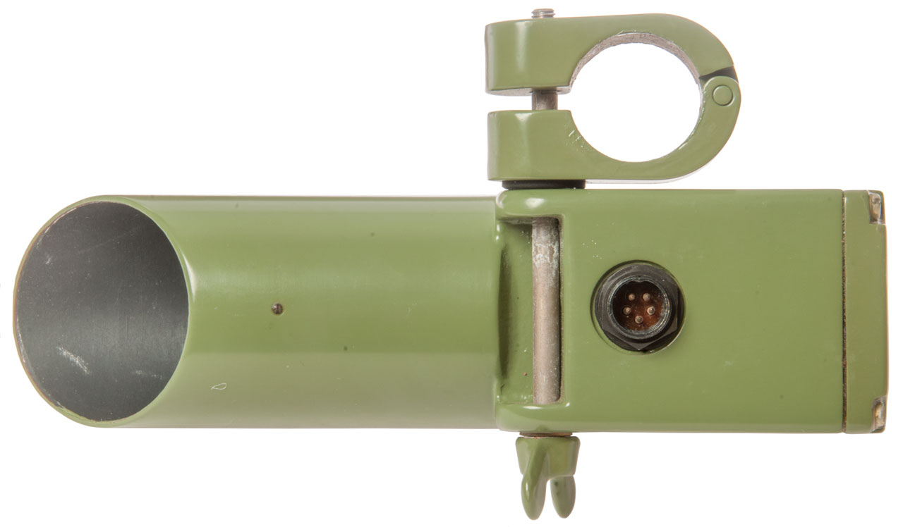
ICO-P
Got this on eBay with title: "Military Optics ICO-P terrain
observation Serbian army" item# 182751050317, Seller: slavors2014,
November 2017.
As this is being written I have no idea what it is. The
connector has 5 male pins so probably not a light source that
would only need 2 pins.
Might be a TV camera, range finder, or . . . .After
seeing that my unit does not have the pot core transformer (Fig
6 from eBay) I now think these are part of a beam breaker system
and my current unit is a receiver and the Fig 6 unit is the
transmitter. While there is provision for 3 wires from the
photodiode/laser diode this unit only has two wires (Orange
& Blue) with the third position empty. It may be that
the laser diode version has the third wire for temperature
sensing?
It appears that there are two very different units both of
which are marked "ICO-P". I'm guessing one is a pulsed
laser diode and the other is a receiver. Note the eBay
listing shows (Fig 6) a large pot core inside, but the unit I
received has no pot core. The pot core is consistent with
a switching mode power supply to drive a laser diode.
26 Nov 2017 I've ordered another unit on the gamble that it
will be a transmitter. Note that both transmitters and
receivers have the same "ICO-P" label, maybe to not make it
clear to an intruder which is the transmitter and which the
receiver, but it would be easy for a sophisticated adversary to
tell them apart based on function.
To tell which is which the resistance between pins 1 and 2 may
be the key, i.e. the receiver unit will measure 300 Ohms and the
transmitter unit will measure something different.
Connector Pin Out
Pin
|
Wire
|
PCB
Terminal
|
Tentative Function
|
Tentative Function 2
|
1
|
Green
|
703
|
Power Supply Negative
|
Power Supply -
300 Ohm resR
C705- (10uF 16V) |
2
|
Violet
|
701
|
Resistor Sense/output
|
Resistor Sense
300 Ohm resL
R714
C701- (10uF 16V) |
3
|
Pink
|
704
|
Power Supply Positive
|
C704+ (10uF 16V)
|
4
|
White
|
n.a.
|
Case/Ground |
Power Supply +
|
5
|
no conn.
|
702
|
|
T704C
|
T701, T702 & T703 are in a row with T701 close to the
photodiode. Looks like an amplifier chain. There's a
low loss cap near T703.
T704 (small dia) and T705 are near outer edge of PCB near T701
T704E R712 (560) = C705+ (10uF 16V)
R714L (560)= T705C
Photos
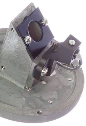
Fig 1 Open gun sights for alignment.
It's made to clamp on a 1" pipe and can be adjusted
in azimuth and elevation.
Lens is about 35mm diameter.

|
Fig 2 Marked: ICO-P
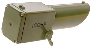 |
Fig 3
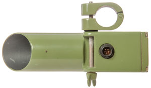 |
Fig 4 The rear screws were coated in clear
potting.
Note there is a hole passing light from the lens.
The screw that's potted in the center of the cover plate
may
be for purging the inside with Nitrogen or other inert
gas.
Shining a flashlight from inside, through the hole,
makes a 3" diameter spot at 5' away.
The 300 Ohm resistor seen below is connected between:
701 (Violet, pin -2) and 703 (Green pin 1).
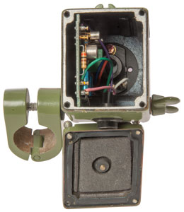 |
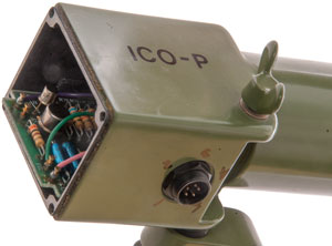
Fig 5 Note lack of pot core transformer
Terminals left to right:
701 Violet pin 2 (resistor sense only)
702: no connection
703 Green pin 1 (Pwr Sup Negative,C705-)
704: Pink pin 3 (C704+)
Case Ground: White pin 4
Resistor is Orange, Black Brown (300 Ohms)
 |
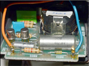
Fig 6 Photo from eBay
Note pot core transformer
Resistor may be Orange Orange Red (3k3 Ohms)
|
Fig 7 Note pins numbered 1 to 5 clockwise
starting at notch.
Terminal numbers printed on PCB 701 to 704 left to right.
|
|
|
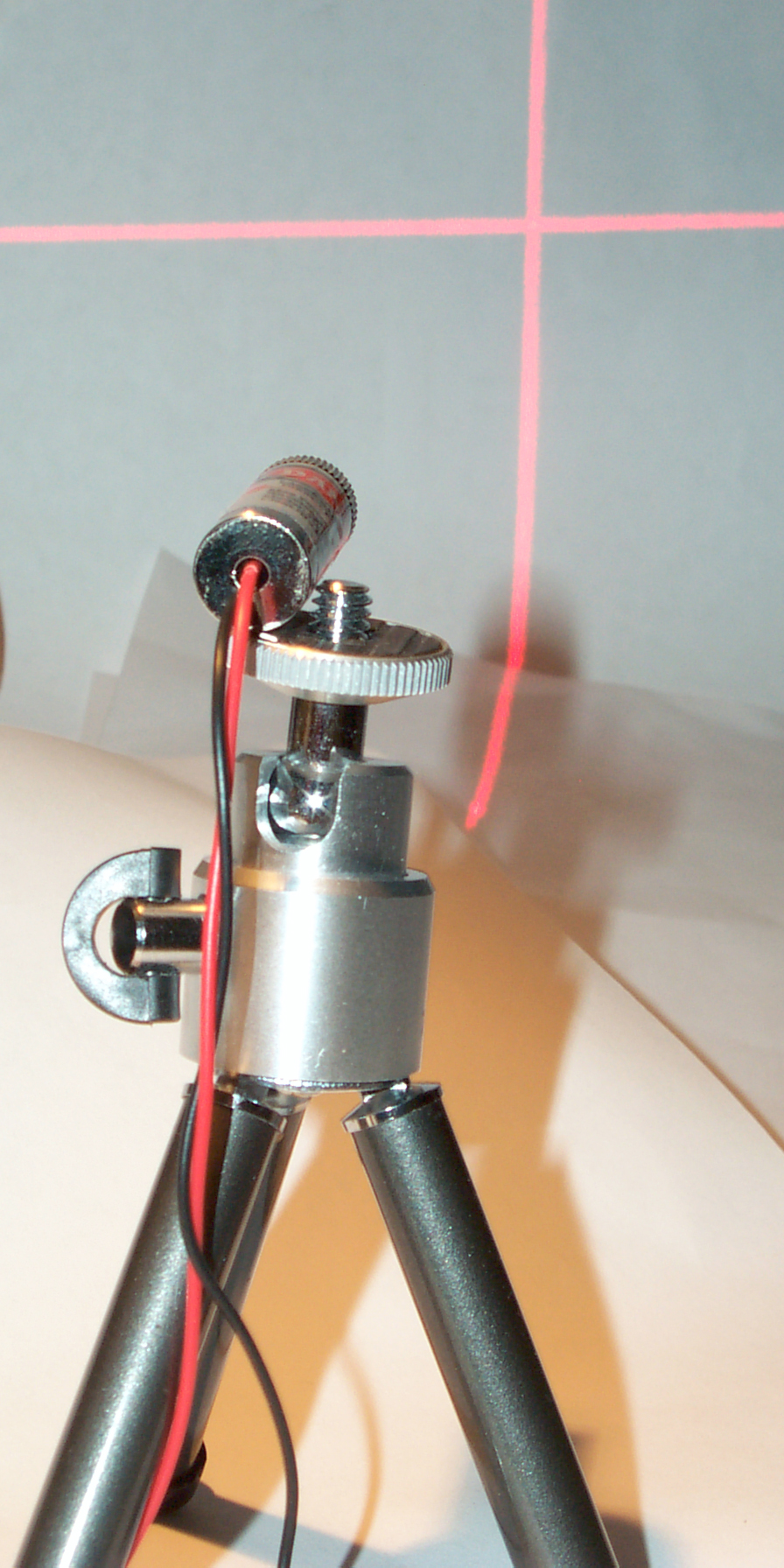
Laser Module 635 nm 5 mw "X"
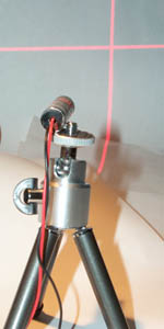 |
This is a laser module that projects a "+" image instead
of just a spot. 635 nm (red) and 5 mw power
level. Max input is 3.2 V. It draws 33 ma at
3.0 volts. |
|
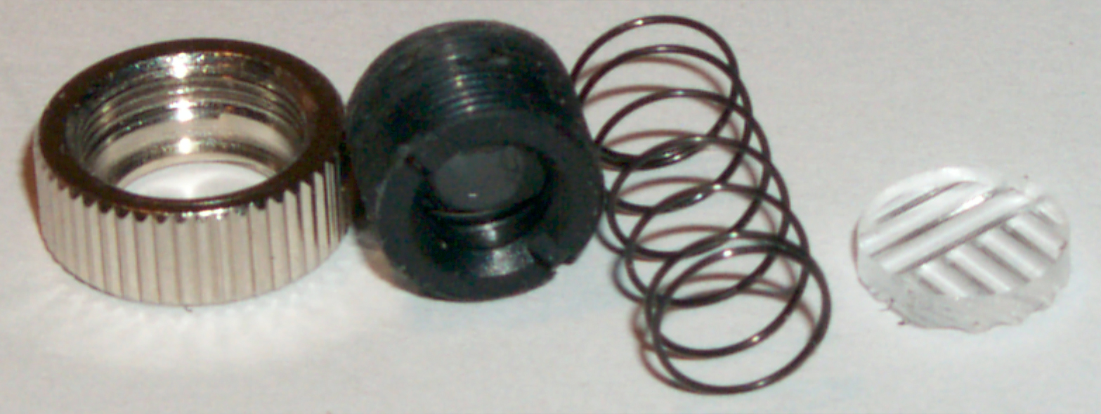
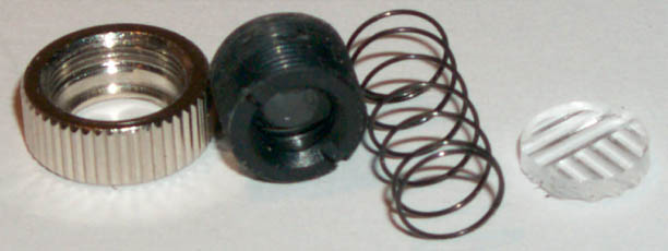
The "X" is produced by the parts shown at the left.
A lens and molded plastic line generator, one half of
which has lines at 90 degrees to the lines on the other
half. It needs to be adjusted by screwing in or out
to balance the brightness of lines.
|
|
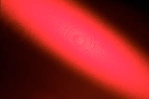
With the optics (lens and line generator removed the beam
looks like this.
When 5" away from the paper the beam is 1" x 5".
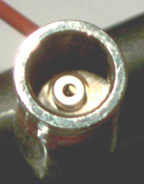
With the laser off, looking into the hole where the light
exits you can see what looks liks the edge of a metal disk
partially blocking the exit hole.
This is the light pattern from a raw laser diode.
The emitting geometry is a thin line and at right angles
to this the beam spreads the most.
|
|
You can see the disk that's blocking about half of the
exit hole.
|
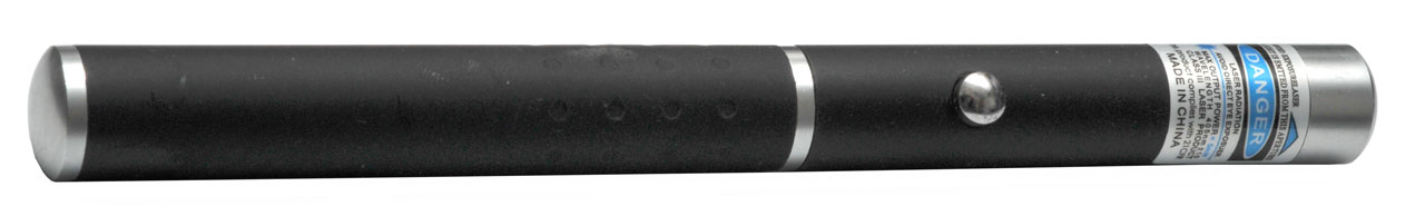
Blue Laser Pen
Runs on two AAA batteries. 405
nm @ 5 mw.
TSL267 IR to Voltage
This is one of the TAOS Light to
Voltage ICs. It takes the current from a photo diode and
drives the inverting input (virtual ground) to an op amp which
converts the current into an output voltage. They typically
offer different model numbers that have different gains and
bandwidths.
22 Jly 2007 - A few minutes using
the
TSL267
with the Battery Top Power Supply and the Printer Encoder Strip
looped back on itself seems to confirm my idea that the slot opto
interrupter is not working because the light source is closer to a
point source than a collimated source. With a point source
the light falling on the strip not only passes at 90 degrees, it
also is at other angles, making it much harder to block the
light. I ran this test in the day time, but room IR
background saturates the TSL267 so need to wait till dark to
really try it out.
22 July 2007 9
pm - Used angle head Flashlight about 4 feet from TSL267 and it's
working.
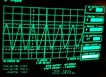
The output voltage goes between 0.67 and 2.63 for a Pk to Pk
signal of about 1.9 volts. The speed I was sliding the
encoder strip on itself resulted in a frequency of about 633
Hz.
So it's important that the light source is collimated and
desirable that it has near IR output.
Blurry photo hand held auto time exposure.
Theoretically the wave form should be a triangle with points at
the top and bottom and the scope image is close but the top and
bottom are rounded so looks like a sine wave. That may be
related to the sampling scope's low one shot bandwidth.
So to use the strip ambient light needs to be blocked and a
collimated near IR source used.
The Light to Voltage family of TAOS parts uses a photo diode as a
solar cell generating a current proportional to the light
input. By connecting the photo diode output to the virtual
ground negative input to an op amp the current gets transformed
into an output voltage The negative feedback circuit
consisting of a resistor in parallel with a cap allows trading
gain and bandwidth to some extent. The rise time for these
varies from a few to a few hundred microseconds.
Methods of using Photodiodes:
- As Solar Cell - no bias -In this mode the output current is
proportional to the light input. At a former residence I
had a small solar panel (1x3 inches) flat on the roof driving
an analog current meter as an indicator of the Sun's
brightness. A voltage meter connected to a solar cell
does not give you the same information. TAOS uses an op amp
connected as a transimpedance amplifier to convert the current
out of an unbiased photo diode (small solar cell) to a voltage
from a low impedance in their Light to Voltage
products. These have a dynamic range of many
decades. There's a tradeoff between high gain for high
sensitivity and lower gain for faster operation.
- Reverse Biased - the leakage current is a measure of the
light on the diode. The back bias lowers the capacitance
allowing the diode to be faster. There are a lot of
complications related to the presence of DC so this method is
typically only used for things like fiber optic receivers
where speed is very important.
- LED used as light sensor - Novel
Fused-LEDs Devices as Optical Sensors for Colorimetric
Analysis - uses PIC micro
controller to first back bias the LED to charge up it's
capacitance (uses 2 I/O pins, cathode ground), then switches
the pin connected to the cathode from ground to a digital
input then grounds the other PIC pin. Now there's
5 volt input to the digital input. The digital input pin
has an extremely high impedance. A timer is started and
stopped when the input switches low (good to make this an
interrupt pin). The time to discharge is a measure of
the light on the LED. Can take a second when light level
is 0.0001 lux).
Very
Low-Cost sensing and Communication Using Bidirectional LEDs,
2003 -
- The output current from the photo diode can be used to
control the frequency of an oscillator. These devices
have the effect of integrating the light level and so are
slower in responding than a photo diode connected as a current
source. This is what's done in the TAOS Light
to Frequency converters.
- also see Integrating
Sphere since they use some of these techniques to get
multiple decades of sensitivity.
Idea for Much Higher Resolution Incremental Encoder
When you look at two identical
Printer Encoder Strips as one is moved over the other the amount
of light coming through varies from completely blocked off (if
they are well aligned) to 50% of the light on the other side of
the strip. So a linear light intensity sensor set so it's
full scale output goes from black to 50% of the light source
will have a saw tooth output as the strip is moved. Two of
these sensors with a separation that's some integer of the pitch
plus 1/4 pitch (i.e. a quadrature sensor arrangement) would
allow not only much finer resolution but also direction of
movement detection.
This method would not be good for fast turning motors but would
be great for things like telescopes that move slowly. Note
that the light intensity is directly proportional to the
effective slit width so the voltage output from the light to
voltage converter is a straight line function of the
displacement of the two strips. Only an offset and scale
factor correction need to be applied.
Instead of taking the photo diode output as a binary signal,
process is through a transimpedance amplifier to get an analog
signal. Use an A/D converter to read how much light is
there. There will be some limit on how many bits can be
added by I expect that 8 bits is not out of the question.
For most applications only the final position is important so
the photo diode output can be split into two channels. One
channel is for conventional digital counting and
direction. During high slew moves the analog channel may
or may not be able to keep up. So a speed based switch
driven from the digital channel can turn off the analog output
or for lower cost just ignore the lower significant digits
during slews. This might be a problem when in a GOTO mode,
so there should be two speeds used, the first for getting near
the target and a slower speed used to creep up on the desired
setting. I think this is how they now work, but would be
required to use the higher resolution mode.
The reasonable priced angle encoders now have 500 slots per turn
(0.72 deg) and the minimum step size you can get is 1/4 pitch
(10.8 min angle).
But this might be changed to 2.5 sec angle using the
analog method.
When the number of bits in the D/A converter gets high enough
variations in the pitch of the strip or wheel will start to show
up. A way around that is to use the index mark to allow
calibration of a complete circle by using an external index head
to set the position and build a table in EEPROM.
Slot Opto Interrupter

This
is a Sharp GP1A50HR (Electronic Gold Mine
G15889
or
GP44).
It's
an
IR
emitter
coupled
with
a
photo
transistor
detector
circuit.
The
emitter
is
about
1.1
volts
@ 15 ma and the detector circuit runs on 5 VDC. Gap is 3 mm
and slit is 0.5 mm.
+5 VDC from the
Battery Top Power Supply
shown below with the TAOS Light to Frequency Converter. By
using solid hookup wire just plug the wire into the socket where
the IC was before.
Clock Escape Wheel
The LED wired to the output through a resistor is on (output is +5
w/empty gap) and turns off when the beam is blocked. By
placing the gap over the escapement wheel on a Self Winding Clock
Co. clock where the wheel has 60 teeth (i.e. 120 beat, or 1
second period pendulum), the LED turns on and off with a one second
period, i.e. it sees each of the 120 moves of the escape
wheel. The response time is in the micro seconds if the
resistors are chosen per the data sheet.
Positioning is touchy when held by hand, but some type of fixture
would solve that.
Printer Encoder Strip
Electronic Gold Mine
G15602.
A
13"
long
x
0.237"
(330
mm
x
6
mm)
with
alternating
clear
and
dark
bars
at
150 line pairs per inch (5.9 lp/mm). The dark lines are
0.157" long ( 4 mm). There is a slot at each end, both
angles at 45 degrees and parallel to each other. I think
this was used on a printer to locate the print head. The
obsolete
HP
Deskjet 3810/3820 Printer series has manuals with product
number C8952A and the encoder strip is marked "C8952A-80005".
At 150 lp/inch one line pair takes up 0.006666" (0.17 mm( which is
smaller than the 0.5 mm slit in the above Sharp slot type opto
interrupter, but that shouldn't matter since when two strips are
in the gap and perfectly aligned but out of phase such the bars
one one strip are aligned with the spaces on the other no light
should get through. And this is what happens. The data
sheet for the Sharp sensor mentiones that the sensor slot is
vertical, i.e. aligned with the long axis of the gap but I don't
think that's much of an issue.
It's impossible to hold a folded encoder strip in your hands and
adjust it to be black for more than about 1/4". The problem
comes when the alignment of the two strips is off a little the you
get a Moiré pattern (
Wiki).
The effect can be calculated (
Wiki).
For
two
strips
with
the
same
pitch
the
big
distance
on
the
pattern
between
dark
lines
is
D = p/a where a is in radians and D and p are in the same
units. So for p = 0.0066666" and a = 1 degree or 0.017453
radians, D= 0.38"
angle
deg (radian)
|
radian
|
D =
|
0.029
(1.7 arc min)
|
0.000513
|
13"
|
0.25
|
0.004363
|
1.5"
|
0.5
|
0.008727 |
0.76" |
1
|
0.017453 |
0.38"
|
2
|
0.034907
|
0.19"
|
4
|
0.069813
|
0.095"
|
19.5
deg
|
0.34
|
0.5 mm
|
If the angle between the two strips was within 1.7 arc min the
whole 13" would appear to be black.
The bottom line is that it's not trivial to make a linear encoder
that works.
If the two strips are aligned to within 19 deg across the 0.5 mm
wide slit then the brightness will be a function of the linear
offset between the two strips which will vary as the phase of the
pitch.
I've heard that the commercial linear encoders use two sensors for
the "A" phase and two for the "B" phase where the two sensors for
the same letter are out of phase so one is dark and the other is
light. Theoretically only one A and one B are needed, but by
using complementary sensors it works better. With the folded
strip this would be an "A" only incremental sensor, i.e. no
direction information.
TAOS Light to Frequency Converter
 The TAOS
TLS245 is an Infrared light to frequency converter that runs from 5
volts. It's packaged in a 3 lead TO-92 like package made of
black plastic that acts an an IR pass filter. So by combining
it with one of my Battery Top Power Supplies
you get a portable unit. The Fluke 87 DMM has the ability to
read the frequency of an AC signal so the whole setup is easy to
use.
The TAOS
TLS245 is an Infrared light to frequency converter that runs from 5
volts. It's packaged in a 3 lead TO-92 like package made of
black plastic that acts an an IR pass filter. So by combining
it with one of my Battery Top Power Supplies
you get a portable unit. The Fluke 87 DMM has the ability to
read the frequency of an AC signal so the whole setup is easy to
use.
Instead of soldering the wires to the sensor I used three Mil-Max
sockets (Mouser 575-067700) this way I can just unplug the TLS245
and plug in the TSL237.
Some readings:
Light
|
TLS245
IR
Hz
|
TLS237
Visible
Hz
|
| dark space |
<2
|
<1
|
| indoors
bright sunny day outside, no lights on |
20 k
|
160 k
|
| Quartz
Halogen desk lamp on low power 18" away |
305 k
|
573 k
|
| Quartz
Halogen desk lamp on high power |
403 k
|
na
|
Outside in direct Sun
|
na
|
na
|
So this sensor can not be used for directly measuring
sunlight. Of course it can if the Sun light is attenuated, but
then the lower end of the dynamic range is also moved up in
brightness.
The TAOS TSL237 is probably the same chip as the TLS245 only in a
clear plastic housing so it can sense visible as well as near IR
light. This is a single range (i.e. single photo diode) sensor
that's been optimized for low light levels and for flat temperature
performance. It's the heart of the Sky Quality Meter used
by astronomers to measure light pollution. Part of the
calibration is to determine the output frequency for a dark input
thus allowing the actual output to be scaled. It may take a
few dozen seconds to get enough counts if the sky is really dark.
The Narrow-band low-cost
spectral light source is another product by the same company
that makes the Sky Quality Meter. It comes in two models,
one with all visible outputs and one with a near IR output.
But they don't say wheather or not the peak magnitudes of each
source are matched. That would allow using it to measure
filters or materials. If not filtered then a calibration
would be needed.
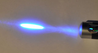
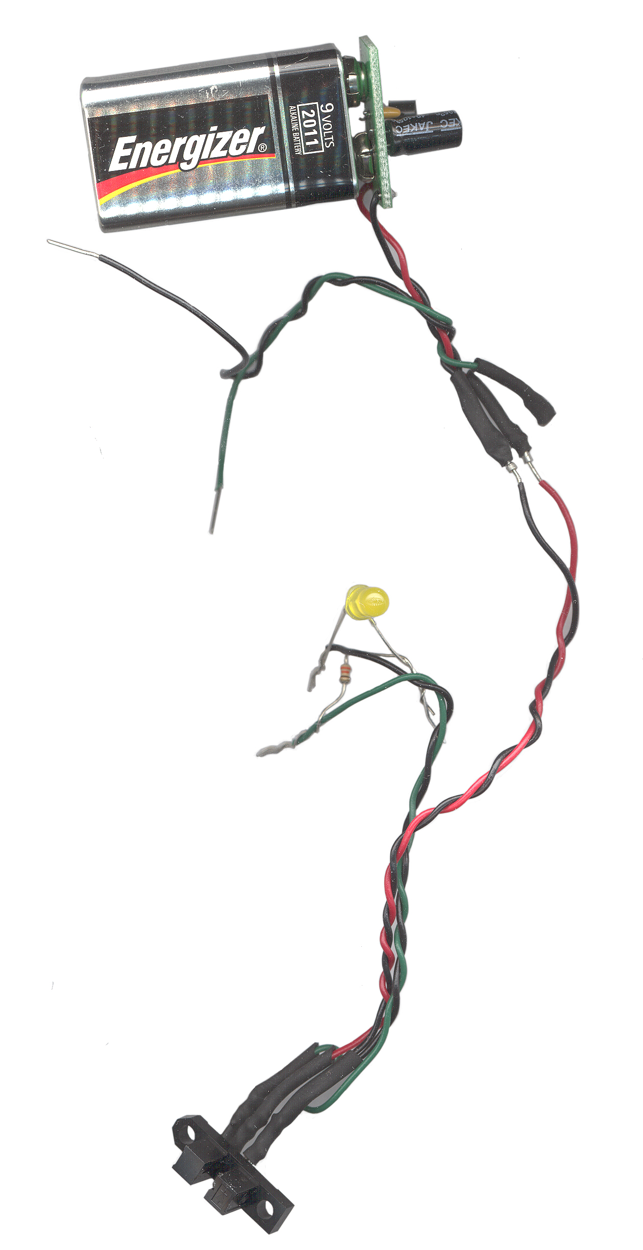
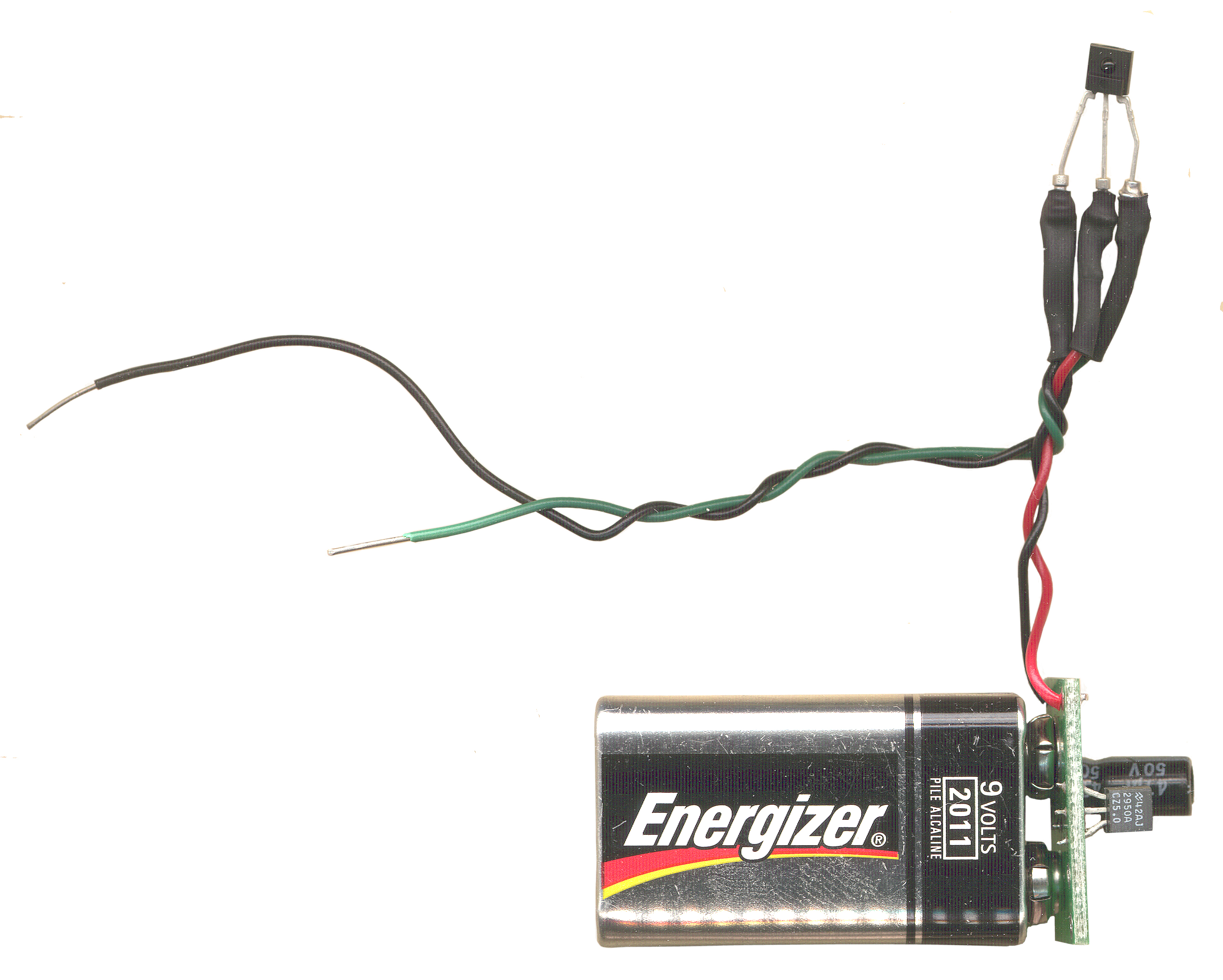
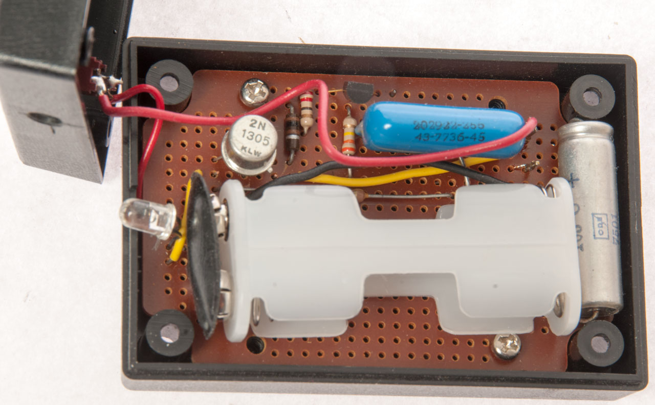
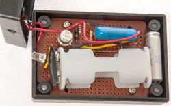
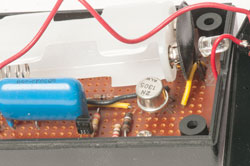
10 Hz IR Avalanche Pulser
 |
This circuit uses a type of
transistor that avalanches and dumps a huge current into a
standard T-1 3/4 IR LED producing a much higher output
than you could get using a short pulse. I think the
circuit was used for beam breaker type intrusion
alarms. Should have a very long range. |
|
2N1305 transistor
Vertical resistors left to right: 200, 22, 330
Horizontal resistor 18
Tubular cap 150 uF 6V
Blue mylar cap: 2029ZZ-Z55, 43-7736-45 probably 0.047 uF
The circuit is similar to - Forrest
Mims Circuit Scrapbook, Volume 1, pg 57 - 3.
High-Current LED Pulser
|
 |
PN2222A
|
|
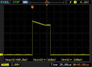
The output pulse is about
50 us wide. The amplitude does not mean much from
this on/off type sensor.
|
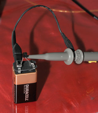
IR Photo Transistor Sensor
This was made by removing the top of
a dead 9 V battery and attaching a QSE156 to ground and +9 volts
and leaving the center output lead hanging so that the Rigol Scope
probe can be connected to ground and output. The motivation
was to see what the pluse stream is coming from a
Nikon SB-900 Creative Lighting
System speedlight. But it was then used on the 10 Hz pulser
above.
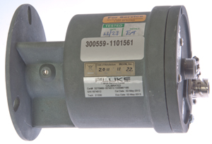
Ircon
DN-DNS30-20C
This is a non contact temperature measurement type S
sensor that was part of the InfarRail system.
Connector
Type: ITTC 1144 7235387 575892
Wiring:
A: +
B: -
C: shield
Fluke 87 V DMM red: A, black: B Diode function 0.582V, reverse
leads: OL.
The sensor is a Silicon Photodiode (Wiki)
Fluke 67 V DMM in mV range red: A, black: B = 300+ mV
under Halogen table lamp, -20 mV under table in sort of dark
The output is slightly higher when the objective lens is used.
maye 340 mV instead of 3.5 mV.
The output would be even higher if the calibration screw was
backed out so it wasn't blocking some of the IR from the mirror to
the photodiode.
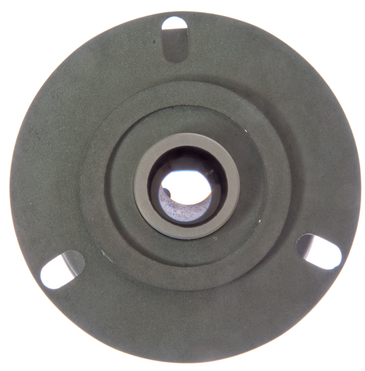
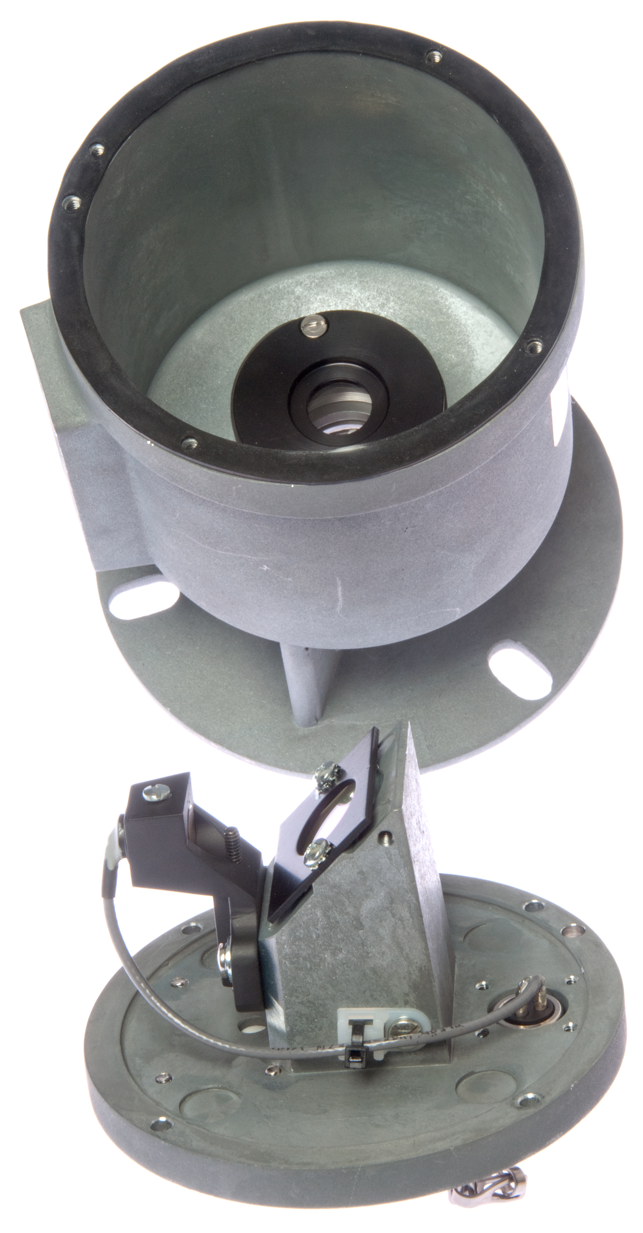
Fig 1
|
Fig 2 Center SLR eyeball port with cap
removed.
CAL screw behind name plate.
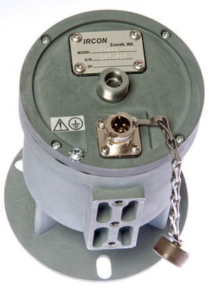
Mounting looks like 1/4-20 holes for standard tripod.
Fluke 87V DMM: Ohms mode: black
A, red B
background OL MOhms to hot 25 MOhms
background 0 uS to hot 50 uS
|
Fig 3 Temperature sensing end
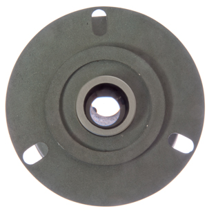
When I wear my reading glasses I can see a very small
circle when looking through SLR port, but not without the
glasses. That's to say there's no diopter
adjustment.
|
Fig 4 Focus tube
To focus - loosen the slotted head (-) screw - slide tube
in/out
to remove - loosen the 3/32" hex screw on bottom
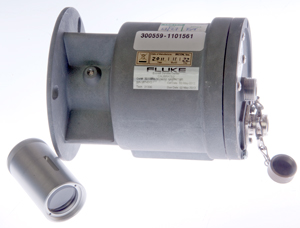
Tube
|
Range
|
P-1
|
18" - inf
|
P-2
|
7" - 20"
|
P-3
|
4" - 7"
|
P-4
|
2" fixed
|
Type type stamped in knurling at front of tube
|
Fig 5 Zinc can and end plate.
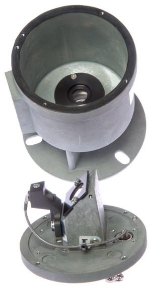
|
Fig 6 Cal screw (behind rectangular label)
is between the
sensor and mirror.
|
Note: Silicon sensors can see slightly longer wavelengths
than the human eye can see so using Silicon for 0.7 to 1.9 um
makes sense.
They also offer another model that uses an InGaAs chip and that
covers 1.5 to 1.6 um.
Wien's
displacement law (Wiki)
relates the wavelength of the peak emission to the surface
temperature of the black body.
So for 0.7 to 1.9 um wavelength the peak black body surface
temperature is 4139 k (3865 c) to 1525 k (1252 c).
The emissivity (Wiki) of the
hot object will have a very large effect on what any IR sensor
sees. The sensor will work well with a black body but will
have problems with something that's more like a mirror.
The part number breaks down to: 0.7 to 1.9 um wavelength Silicon
sensor chip with a temperature range of 1100 to 2000 deg C.
The resolution is D/300 when the focal distance is 18 inches.
d = D/300, so at D=18", d = 18"/300 = 0.060" (closest focus
distance for P-1 optical tube).
at longer distances the spot size increases in proportion to the
distance. at 3 feet it would be 0.120", at 30 feet it would
be 1.2", etc.
Light to Audio
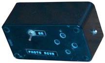
A photo sensor is AC coupled to an audio amplifier that drives a
small speaker. An easy way to tell if there's modulation on a
light beam. The Valantine
1 Radar detector will sense any modulated light, even at video
frame rates.
Even though you can't hear 10 Hz, you can easily hear a hammer
pounding on a log at 10 Hz. So this box let's you hear and
confirm that the 10 Hz pulser above is working.
LM3909 LED Blinker
 This
is just a garden variety LED blinker based on the LM3909. I
think the LM3909 was developed for use in aircraft
flashlights. It seems that whenever I was in a commercial
plane there were a number of flashlights mounted to the wall with an
LED blinking about once per second. I also remember reading
that a battery would last for it's shelf life while blinking the LED
or maybe longer that the specified shelf life. That indicates
that the internal battery loss mechanisims were using more power
than the blinker. It workd using the flying capacitor
principal. The capacitor gets chagred up then it's switched to
be in series with the battery so you get a 3 volt pulse to the
LED. Note that connecting a single 1.5 volt battery to an LED
will not turn it on. The circuit needs to be very cleaver to
work from less than a volt when the battery is approaching dead.
This
is just a garden variety LED blinker based on the LM3909. I
think the LM3909 was developed for use in aircraft
flashlights. It seems that whenever I was in a commercial
plane there were a number of flashlights mounted to the wall with an
LED blinking about once per second. I also remember reading
that a battery would last for it's shelf life while blinking the LED
or maybe longer that the specified shelf life. That indicates
that the internal battery loss mechanisims were using more power
than the blinker. It workd using the flying capacitor
principal. The capacitor gets chagred up then it's switched to
be in series with the battery so you get a 3 volt pulse to the
LED. Note that connecting a single 1.5 volt battery to an LED
will not turn it on. The circuit needs to be very cleaver to
work from less than a volt when the battery is approaching dead.
Yet another LM3909 LED blinker, this time with a different LED
installed.
These are fun to have around, kids really like them and I used to
give them away.
For many years now the LM3909 has been out of production and the New
Old Stock ones go for a big premium.
Here is another LM3909 LED Flasher, this one was started for Chinese
New year Feb of 2007 and since it's only July now is still
blinking. These "D" cell blinkers last over a year.
In the 1950s I had a 90 volt battery connected to a resistor and
capacitor that blinked a NE-2 Neon bulb in a similar manner.
But that version went for a number of years on one (larger) battery.
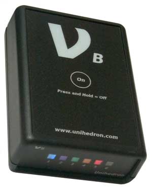
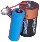
This is a light source with 6 different wavelengths. The light
comes from LEDs that may also have some filtering. The LEDs
are pulse width modulated to sort of equalize the brightness of
each. This is the Nu-B-IR version where the No. 1 LED is white
(peak in spectral response around 450 nm), then blue, green, yellow,
red and IR (950 nm).
Note: To turn off, PRESS AND HOLD THE BUTTON.
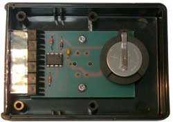
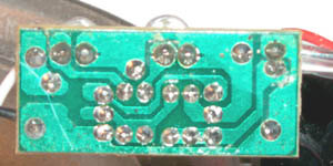
The heart is a PIC 12F509 and a very simple circuit. Since
there is no voltage regulator the intensity of the LED depends on
the battery voltage ( 2 each CR2032 3V Lithium coin cells).
Solar
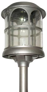
Solar House Number
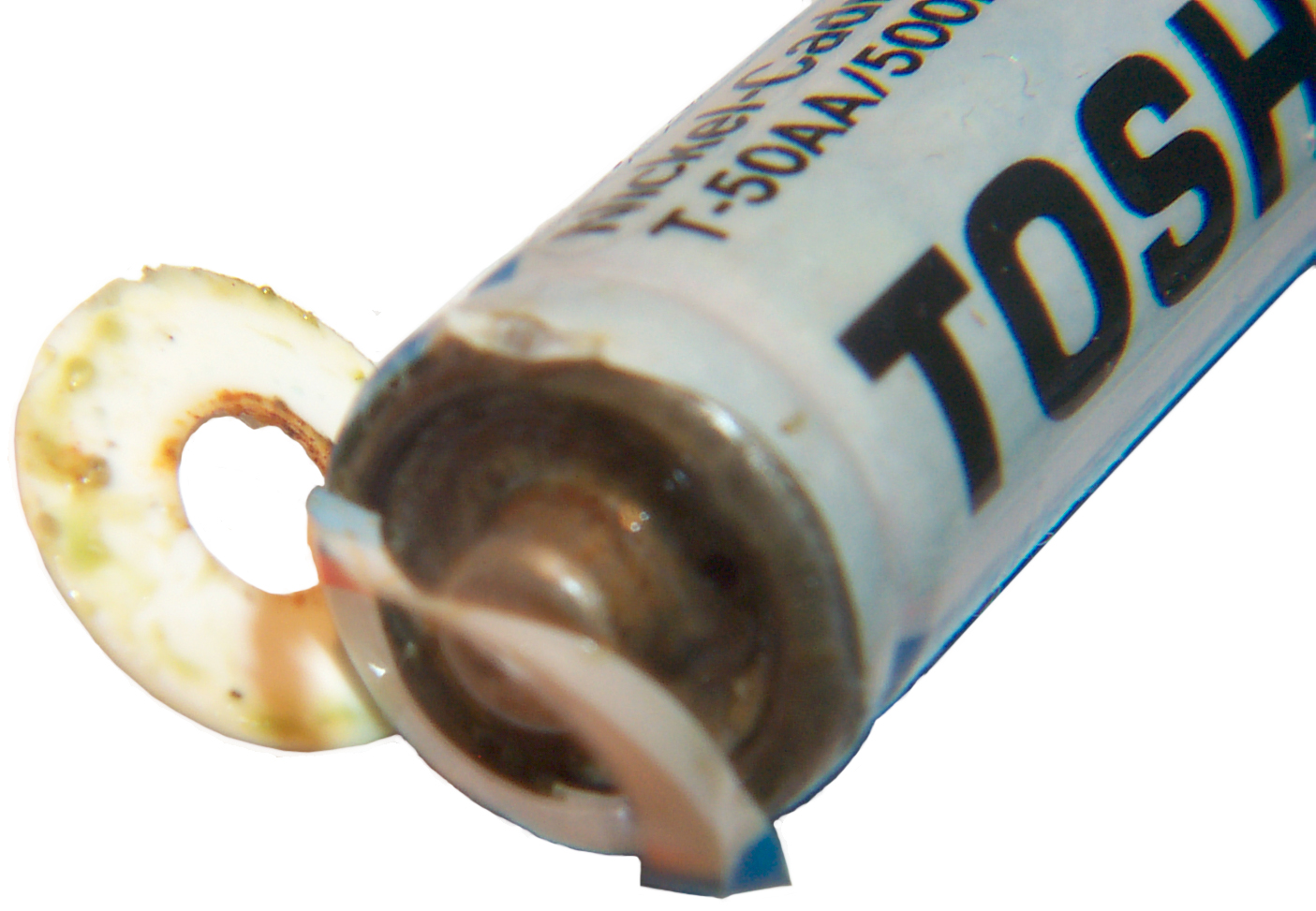
This worked for a while then quit. pulling the three AA
batteries showed why. One of them had blown it's top (vented)
and put slime on the others. The most probable cause of
the battery venting is the cells were enough different in capacity
that the weak cell was driven into reverse polarity by the stronger
cells.
This is a problem with any battery pack where there are series
connected cells. If one cell is too much weaker that the other
cells it can be charged by the other cells which are discharging.
5522540
Solar powered illuminated address number device and mailbox, cites
many prior art patents.
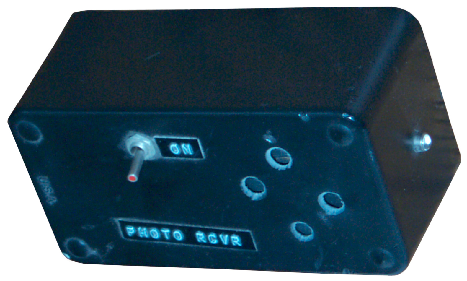
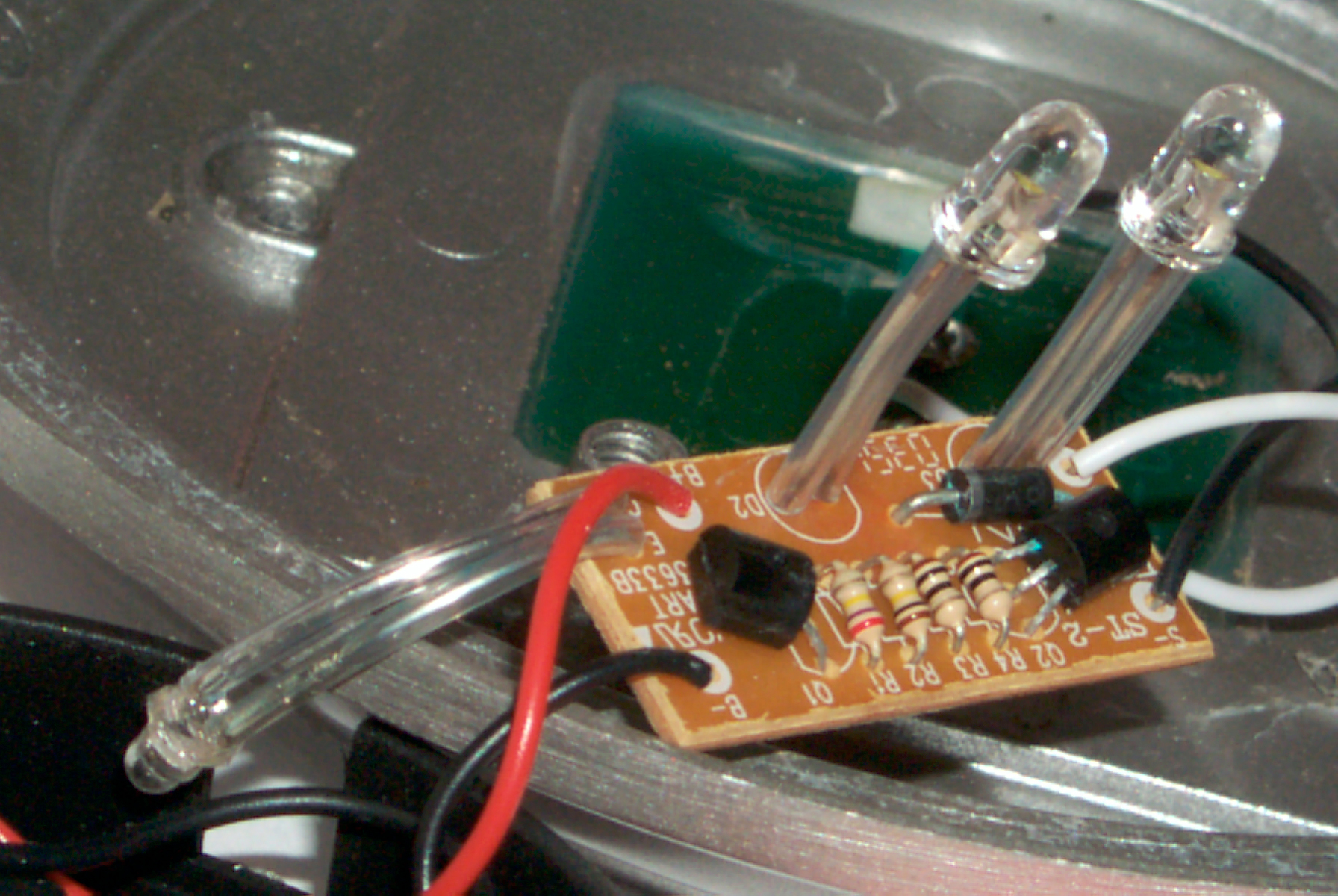
Solar Garden Light

|
|
Black
battery holder, photo diode, w LEDs green is the back
side of the solar panel.
This
may be a sililar circuit dirgram
|
PCB
|
After reading an interesting analysis of two different
Solar
Garden Lights I got one to see the high technology they
contain. The interesting ones have a single cell battery to
store the power so they include a Switch Mode Boost Power Supply
to get enough voltage to drive a LED.
This one has a metal cylindrical frame about 5" dia x 6"
high. A square solar panel a little smaller than 2.5" on a
side drives the electronics. Three AAA Ni-MH cells store the
power. A photo diode senses if it's night. Two 5 mm
LEDs shine down and some light would fall in a circle around the
fixture and what light hits the bottom reflector is spread
horizontally. The batteries were dead (this is a used
discount store unit) and are now on the
C401FS
charger, then to the
C9000 for
discharge analysis and cycling. Since there's a three cell
battery no need for the SMPS.
The batteries showed fully charged in less than 10 minutes.
They are rated at 1.2 Volts and 600 mAh. Discharging them
showed about 33 mAh capacity, so they now are on the Break-in mode
of the C9000. After the Break-In the cells now have 279, 229
and 308 mAh capacity almost 10x what they were down to after
sitting. But it's still half the label capacity.
After installing the batteries the light did not work. The
voltage at the PCB was low. Rubbing the battery terminals on
my pants and after installing rotating the cell in the battery
holder fixed that. Now when the photo diode is put in the
dark the two LEDs turn on. Used Radio Shack Lube Gel
(Silicon Grease) on both ends of each battery. You might
think that's an insulator and would stop good contact, but that's
not the case. There's enough spring pressure for the metal
to push the weak grease aside and make contact. But Lube Gel
is made without any entrapped oxygen so no air can now get to the
joint to allow it to corrode.
|
|
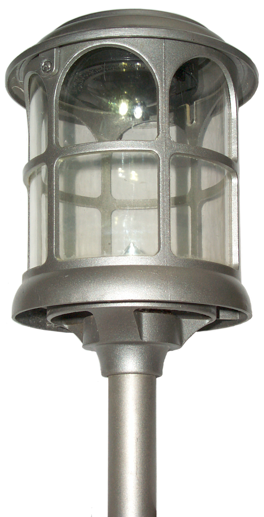
Working
Solar Garden Light
|
|
Put outside in a spot that gets some Sun, but only an hour or two
per day around Xmas. Light came one at dusk (noticed it was
on at 5 pm) and at 7 am the next morning it's still on.
If each LED was running at 3.3 Volts and 10 ma that would be 20 ma
total and if the battery capacity was 600 mah the max run time
would be 30 hours. Off at about 7:13 at dawn probably not
because the batteries have run down.
The job of the circuit would be to turn the LEDs on and off based
on how dark it is outside. It's hard on Connect the solar
panel to the battery when there's charge to be had in the most
efficient manner possible an. Three Ni-MH cells and the
white LEDs are a good match. For example it's desirable to
stop the discharge of Ni-MH cells at about 1 volt per cell, or in
this case at about 3 volts. The LED forward voltage is that
of a diode so as the battery voltage goes down as it becomes
discharged the LED current also decreases.
My guess is that the number of hours of light depends on how much
solar energy gets put into the battery. During the winter
it's only going to get a couple of hours of sun and I've not put
in into the ground plumb, but rather with the top pointing kind of
toward the sun. If this solar panel is like the one below
for the solar fountain pump (35 mw/sq in) then it's good for
about [35 * 2.5 * 2.5 =] 220 mw for some number of
hours. The voltage at the end of charging three Ni-MH cells
is about 4.2 Volts so in the ideal case 220 mw could provide 50 ma
of charge current and so it would take 12 hours to fill the
battery to 600 mah or considering the battery efficiency more like
18 hours. Some type of power point charge controller that
matches the panel to the battery would help get more charge into
the battery.
It's clear that in the winter time the battery is going to be
operated most of the time at empty with only a small amount of
charge and back to empty. Being on all of last night was
because I charged the battery.
It may be that under these conditions the newer Ni-MH cells that
have extended shelf life would improve the performance. This
is just a guess based on the idea that self discharge may be more
important when the battery is not fully charged.
A low resistance super capacitor probably would be a better energy
storage method. The idea is that they should have better
efficiency that a battery.
27 Dec 2007 light was on again last night about 28 hours
total. It's cloudy today.
1 Jan 2008 - the light has been on every time that it could be
that I've checked. I.e. it's on a little past 5 at night and
till 7 something am. There's no way it's getting enough
direct Sun light to charge the batteries and my initial charage
would have worn off by now, so the solar panels must generate a
small current just from the sky light.
Second Solar Garden Light
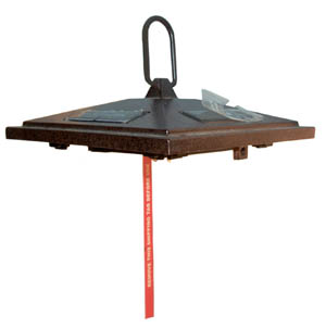
This
light also uses 3 AAA Ni-MH cells and after charging them the
capacity was very poor (around 30 mAh instead of the label 750
mAh). After using the break-in function on the Maha C9000
the capacity was 420, 451 and 706 mAh which is too dissimilar to
use in a series pack. The problem being that when the lowest
capacity cell is discharged the other cells will power it in the
reverse direction which rapidly ruins that cell and can cause it
to vent. That's probably the cause of venting in the
Solar House number.
This appeared to be a new unit. It had a red flag, like is
used on aircraft "Remove Before Flight", only this one says
"Remove This Shipping Tab Before Use" and has one end inside the
battery compartment seperating a battery terminal from the battery
holder contact thus opencircuiting the battery pack. Also
there are clear plastic protectors on the four solar panels with
the legend "Note, Please peel off this protecting film before
use."
Photo taken after removing the top from the rest of the light.
You can see that there are solar panels each about 2 1/8" x
3/4". There's also a photo diode on the top. Two 5 mm
plastic LEDs for the light and three AAA batteries for power
storage. I'm guessing the time and temperature profiles of
storage or poor initial quality of the batteries or both resulted
in bad batteries when in as new condition.
Solar Garden Light or Marker Light Patents
4486820 Lighting equipment with a solar cell, Y. Baba (Kyoto
Ceramic Co), Dec 4, 1984, 362/183; 362/157; 362/190; 362/276;
362/394; 362/395; 362/431; 362/802; 361/171; 136/244 -
a 4 W fluorescent lamp can be lit
for 6 hours with the use of a solar cell of 16 V, 12 W and a
battery of 12 V, 90 AH.
4816970
Solar powered light Mar 28, 1989
5065291 Marking Light, J.S. Frost et al (Atlantic Richfield Co),
Nov 12, 1991, 362/183; 362/431; 362/31; 362/800; 362/145; 136/291
- small solar panel, minimal one transistor circuit and LED. - The
battery voltage must exceed the LED operating voltage and the
solar panel voltage must exceed the battery voltage. simple
cleaver circuit.
5221891 Control circuit for a solar-powered rechargeable power
source and load, R.W. Janda, Jun 22, 1993, 323/350; 323/906;
320/21; 320/61; 362/183 - 2.7V, 180 ma solar panel, 2 x SubC
Ni-Cad cells, 3 transistor control circuit, #1767 2.3 volt
incandescent lamp patents 5086267 5041952 use a very similar
circuit
5984570
Self energized automatic surface marker Nov 16, 1999
6013985
Sealed solar-powered light assembly, David R. Green (Carmanah
Tech), Jan 11, 2000, Jan 11, 2000, 315/149; 315/159; 362/183;
362/800 - two timers, voltage reg, cur lim resistors on multiple
LEDs - not too efficient
6406163 Solar cell lighting fixture integrated with heat sink,
Tai-Her Yang, Jun 18, 2002, 362/183; 362/374; 362/276 -
diminishing effect of solar heat on batteries and electronics
6573659 Solar-powered light assembly with automatic light control,
Ion Toma (Carmanah Tech), Jun 3, 2003, 315/149; 362/372 - uses
micro controller to dim light to allow it to stay on all night
based on charge obtained the prior day.
6729742 Solar lamp for outdoor use, W. Wismeth, May 4, 2004,
362/183; 362/153.1; 362/431; 136/206 - seperate light sensor diode
& solar panels facing different directions
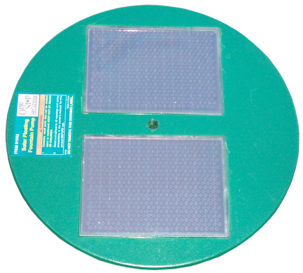
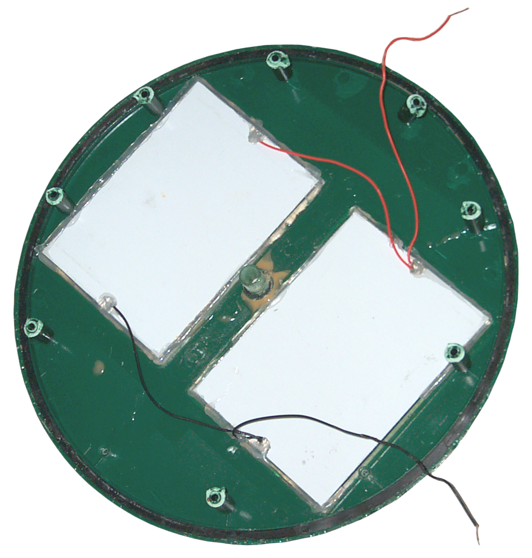
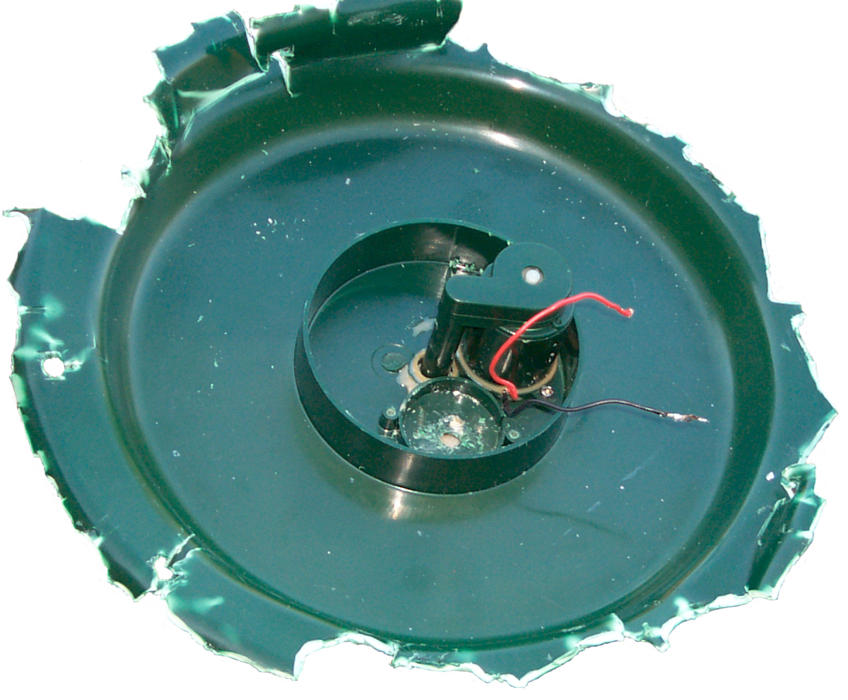
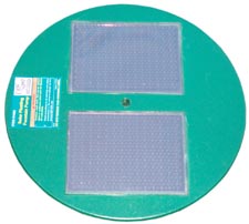
Small Solar Panels
|

|

|
Sun
side pump outlet in center
|
bottom
of panels
|
bottom
with pump
|
My wife wanted to try out the Harbor
Freight
91962
Floating Solar Fountain Pump but it came DOA. After going
thought the RMA procedure they said there was no need to return
the dead one so I opened it up in the hope of recovering the solar
panels, which worked. The probable reason for the DOA is
very poor soldering at the joint between the panel wires, the pump
wires and a 1N4739A 9.1 Volt Zener diode connected cathode to red
wires (positive), i.e. normally back biased by would limit spikes
from motor that might exceed the solar panel breakdown voltage.
The two 6" x 4¼" panels are connected in parallel and put out
about 11.7 Volts in direct sun. Short circuit current of 165
ma, but those are not at the same time. So the power out is
going to be less than 2 Watts. The Harbor Freight 41144 5
Watt Solar Battery Charger is 18" x 12.5" or about 3.3 Watts /
square foot. At that rate these two panels would be about
1.2 Watts.
Pump Testing
The pump while pumping water draws:
# AA
Batt
|
H2O
Ht"1
|
mA
|
V
|
Ohms
|
W
|
4
|
1
|
220
|
3.95
|
18
|
0.9
|
5
|
2
|
240 |
6.5 |
27
|
1.6
|
6
|
4
|
250 |
7.6 |
30
|
1.9
|
7
|
8
|
213 |
8?
|
38
|
1.7?
|
8
|
16
|
240
|
10
|
42
|
2.4
|
Note 1 estimated, not measured
Load Testing Solar Panels
By measuring the voltage across a load resistor the power can be
computed as( V * V) / R.
Load
Ohms
|
50 W
Desk Lamp
Volts
|
50 W
D.L.
mW
|
Oct1
noon
Volts
|
Oct
noon
mW
|
10
|
0.099
|
0.98
|
1.5
|
225
|
20
|
0.042
|
0.088
|
ng
|
ng
|
47
|
0.83
|
14.7
|
6.4
|
871
|
57
|
x
|
x
|
7
|
860
|
67
|
x
|
x
|
7.3
|
798
|
Note 1: Not really direct Sun, some tree filtering. October
has less Sun energy than July.
Looks like 35 mw/sq in. [900 mw / (6 * 4.25)]
5040726 Solar energy powered water fountain , A.T. Dimitri, Aug
20, 1991, 239/17; 239/18; 239/20; 239/22 - seperate solar panel
6435422 Floating Fountain, Mark Wutschik, Aug 20, 2002, 239/23;
239/18 -this floating fountain
Glow
I'm using the word Glow to describe
light sources that generate light without flame and that get their
energy from being excited by photons. The photons may be
visible light, UV light or radiation.
Fluoresce (Wiki)
relates to changing the wavelength from one value to
another. For example a fluorescent light changes UV to
visible light. (see the 8-Day Aircraft
clock)
Phosphorescence (
Wiki)
relates to a light generating process that stores the external
energy and releases it over some time (glow in the dark).
Military aircraft (and probably civilian planes) have
phosphorescent paint on the dials and hands of the instruments
(see the 8-Day
Aircraft
clock). There are also
UV
bullet style lamps in the cockpit that illuminate the
instruments. This way the pilot maintains his night vision
while being able to read the instruments.
Tritium illumination where radio
active alpha particles supply the energy to excite a fluoresce in
a phosphor or scintillator (
Wiki).

2749251
Source of luminosity, Shapiro
Edward, Tracerlab
Inc, 1956-06-05, - prior art made use of Radium (Wiki).
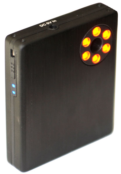
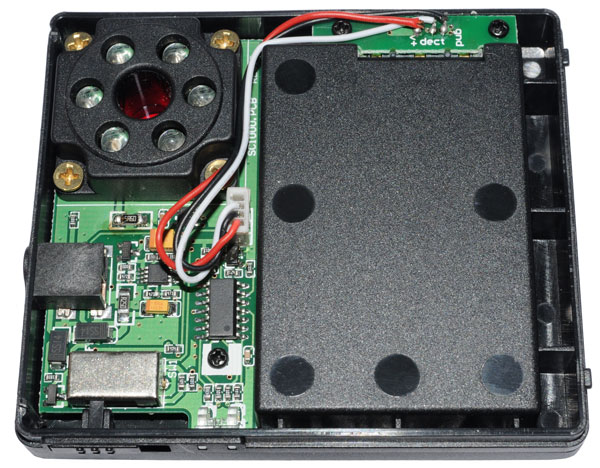
Optical System Detector
Detects hidden cameras.
Powered by a 3.7 V Li-Ion battery NP120/D-L17.
The supplied universal wall wart supplies 5 V @ up to 2 A and will
power the unit and charge the battery.
|
The three way switch has
positions:
Off
Flash
Steady (this photo)
This detector does not use a telescope or lasers like in
the patent, but instead has a 1:1 view and uses
LEDs. The central viewing port may has a red filter,
but no magnification.
|
|
|
|
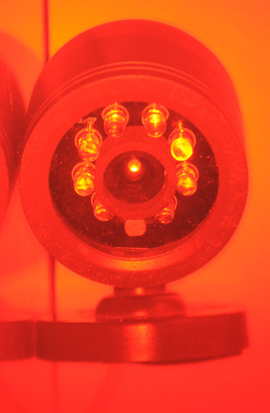
This is a view through the
optical system detector.
Note the central camera lens appears like it was a light.
Also the LEDs appear bright even though the subject camera
is not connected or powered. So this device also detects
LEDs that have a built-in lens.
To take this photo the camera was focused on the TV camera
without the optical system detector then the detector was
placed in front of the lens. The camera took a time
exposure.
|
Aircraft Cockpit UV Instrument Light
I first learned about these in the
1960s while in the Air Scouts. We met at Moffett Field NAS
in Mountain View and one of the things was to try and fly a
simulator. There were UV lights that looked a lot like this
one that caused the pointers and digits on the panel instruments
(like an
8-day clock) to glow yet there
was no white light allowing good night vision.
Popular Science, November 1942, Black Light Aids Night Fighters (
Google
books & Scroll down), pg 62 - about using UV light in
aircraft cockpits.
"Instrument panels on military planes can be made to glow under
black light. Dials, pointers, and controls coated with
fluorescent paint would give off a soft radiance under the rays
from an ultraviolet lamp above the pilot's shoulder.
Ordinary illumination produces terporary night blindness in the
pilot every time he glances at his instrument panel, making it
difficult for him to spot an enemy plane for several
seconds. The same system can be used on naval patrol boats
to help the officers keep a keen watch for enemy submarines."
. . .
"Research this summer has produced new types of bulbs particulary
plentiful in black-light radiation. Black-light lamps now
range from a tiny three-watt 12 to 16 Volt lamp developed by
Eugene W. Beggs and Daniel S. Gustin, of Westinghouse, to a giant
searchlight with a white candle power of 350,000,000 capable of
throwing an invisible beam several miles."
Westinghouse Patents related to UV & W.W.II
Daniel S. Gustin
1813572
Lamp base,
Daniel
S Gustin,
Westinghouse
Lamp Co, 1931-07-07,
220/2.3R; 220/2.1R; 439/615; 313/318.03;
313/318.04 -
2082954
Prefocused lamp base,
Daniel
S Gustin,
Westinghouse
Lamp Co, 1937-06-08,
313/315; 264/82; 264/271.1; 362/95; 445/4;
313/318.01; 249/96 - pre-focused flange type for precision
applications. Maybe scientific instruments or headlights
for cars?
2110597
Discharge lamp, Daniel
S Gustin, Westinghouse
Lamp Co, 1938-03-08, 315/47; 315/32; 315/100; 315/60; 315/335 -
2171237
Vapor lamp, Daniel
S Gustin, Westinghouse
Lamp Co, 1939-08-29, 315/48; 313/26; 313/256; 313/629; 313/15;
313/27; 313/266; 315/266 - temperature controlled
Sodium Vapor lamp
2259954
Lamp and operating circuit, Daniel
S Gustin, Westinghouse
Lamp Co, App: 1938-11-30, Pub: 1941-10-21, 315/102; 315/266; 315/122 - "..ultra-violet lamps of the gaseous conduction
type, in which the bulb is provided with a window of extremely
thin glass for efficiently transmitting the generated light."
Called by:
5177407
Glow discharge lamp having dual anodes and circuit for operating
same, Valery
Godyak, GTE,
Sylvania, 1993-01-05, 315/260; 313/491; 313/581; 313/621; 313/632; 315/266;
315/337 - Patent
Citations (19),
Eugene W. Beggs
2046363
Precision lamp adapter,
Eugene
W Beggs,
Westinghouse
Lamp Co, 1936-07-07,
439/628; 362/306; 362/362; 313/318.03
-
Westinghouse
2255431
Molded fluorescent lamp, John W Marden, Meister George,
1941-09-09,
313/485; D26/89; 220/2.1R; 313/493; 313/609;
362/253; 362/260 - building ceiling fixture & bulb
2258765
Radiating apparatus and method,
Robert
F James,
Westinghouse,
App: 1934-07-11, Pub: 1941-10-14,
426/248; 4/233; 62/264; 313/112; 313/573;
315/282; 315/336; 315/358; 607/92- "... for the
generation of ultra-violet radiations having a desired
bactericidal effect without producing detrimental reaction, ..."
2349754
Method and instrument for measuring ultraviolet radiations,
Thomas
R Porter,
Westinghouse,
App: 1940-11-30, Pub: 1944-05-23,
250/362; 250/368; 359/350; 250/372; 359/885 -
"... output of lamps which generate bactericidal radiations."
2336960
Discharge lamp,
Edmund
A Reuter,
Dewey
D Knowles,
Westinghouse,
App: 1941-08-13, Pub: 1943-12-14,
313/15; 313/42; 313/243; 313/249; 313/256;
313/339; 313/619 -
2349360
Disk-type fluorescent lamp, John W Marden, Meister George, App:
1942-01-24, Pub: 1944-05-23,
313/493; 313/581; D26/79-
2392333
Miniature fluorescent and/or glow lamp,
Morehead
Chalmers, CBS Corp,
Westinghouse,
App: 1943-12-20, Pub: 1946-01-08,
315/48; 315/185S -
2401998
Electrial discharge device,
Williams
Ralph Harry,
GTE
Sylvania, App: 1943-06-19, Pub: 1946-06-11,
313/310; 313/325;
313/352; 313/491; 313/619; 313/621 - Has the look of the
GE UV lamp shown in
Fig 4 below. "a
small fluorescent bulb in dimension of the order of one inch by
two inches and designed for use on low Voltage D. C. of the order
of 20 to 30 volts, this bulb contains argon and mercury and has an
anode and a cathode for supporting an electron discharge."
2777091
Ultraviolet lamp, Frederick H Rixton, CBS Corp, Westinghouse, App:
1952-04-30, Pub: 1957-01-08,
315/48; 313/112; 313/575 - for the
generation of Ozone.
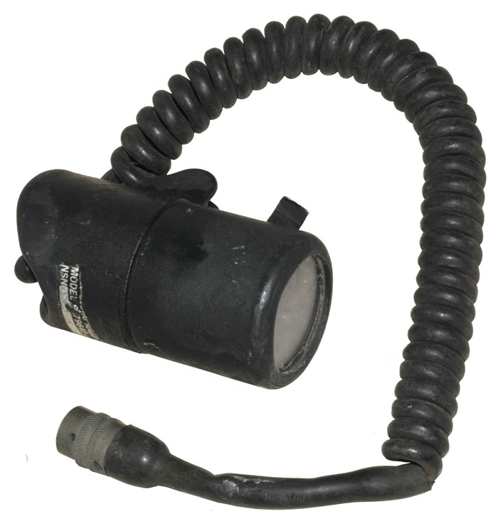
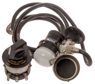
MODEL 9379640
This one has what appears to be a pre-focused flange type
flashlight lamp. The front lens is clear plastic and behind
it there's a blue filter that can be rotated 90 degrees by a
rectangular knob. There's a push on-off switch under a
rubber boot at the rear. The 3-pin cable connector is marked
MS3116E8-33P. The cable is marked:
19200-9379604 and RAYCHEM. The body is marked (hard to read)
MODEL 9379640.
There's rust inside. The lamp works but the push-button
switch is dead and open.
|
|
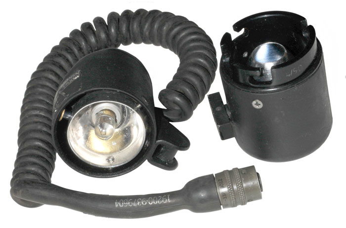
The front can be removed by pressing in and turning
CCW. The bayonet style lamp "313 919" (@1000bulbs?)can
be replaced also.
28 Volt - 0.17 Amp - T3.25 Bulb - Miniature Bayonet Base
The front has date code 4/90.
The 3 screws on the back can be used to center the
filament with respect to the reflector in the front part.
|
Grimes AN-3038-2A aka C-5A
This is the improved version where instead of rotating the filter
cap it can be removed providing much more white light. Also
when the cap is installed there is no white light leaking out.
Ultraviolet Cockpit Light
Found an eBay listing for a Ultraviolet aircraft cockpit
lamp. Missing the bulb, so didn't bid. Markings:
Ultraviolet Cockpit Light
Type AN 3038-2A (these were also called C-5 lamps)
Grimes D-2332
Pat 2324384
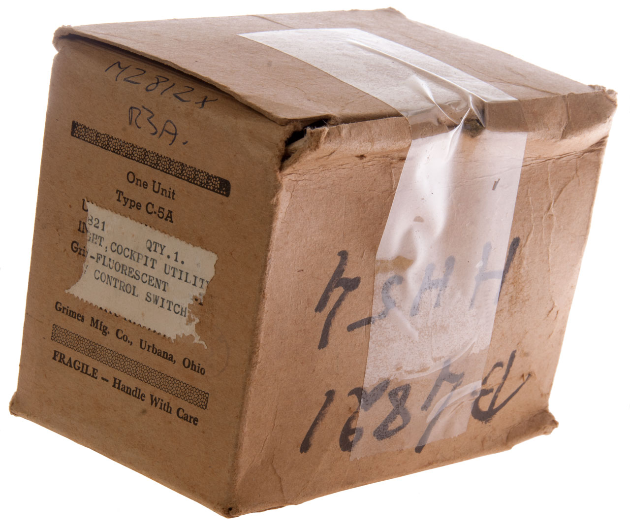
Found another one new in box with starter controller.
2324384
Ultraviolet screen for fluorescent lamps,
Warren G Grimes,
1941-06-30 - (14) "fluorescent lamp" is shown as a filament bulb,
like would be used in an old car tail light.
This is a very specialized fluorescent lamp, not a filament
lamp. It requires a rheostat with a "Start" position.
See:
Lights,
Lights...- for wiring diagram
Wiring
Rheostat
|
Lamp
wire
|
Description
|
1
|
Black
|
Start
|
2
|
White
|
Lamp Brightness
|
3
|
nc
|
+24 VDC
|
nc
|
Shield/Gnd
|
24 VDC ground (-)
|
Rheostat
Off: Open 2 to 3
On-Dim: 145 Ohms 2 to 3
On-Bright: 33 Ohms 2 to 3
Start: 28 Ohms 2 to 3 & Short 1 to 2
Lamp
Black to A- (ground): 5 Ohms [starter filament]
Manuals
TM 1-406 AIrcraft
Electrical Systems, Feb 1945
NavAer 08-1-507 Navy
Airborne Electrical Maintenance Notes, Sept
1945. - "...lamp operated directly on 28 VDC without the
necessity of an inverter".
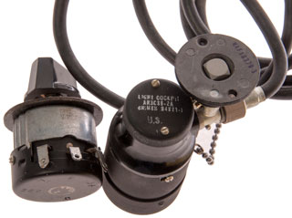
Photos
Fig 1 New Old Stock UV Cockpit Light &
Rehostat-Starter

|
|
Fig 2
 |
|
Fig 3 Note filter blocks white light coming
up from light table.
 |
|
Fig 4 GE MF 5000 DC
Florescent lamp
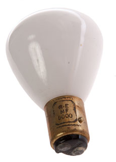 |
This is probably a BAY15D base.
I have some automotive lamps on order to check that.
Maybe based on patent 2401998
Electrial discharge device |
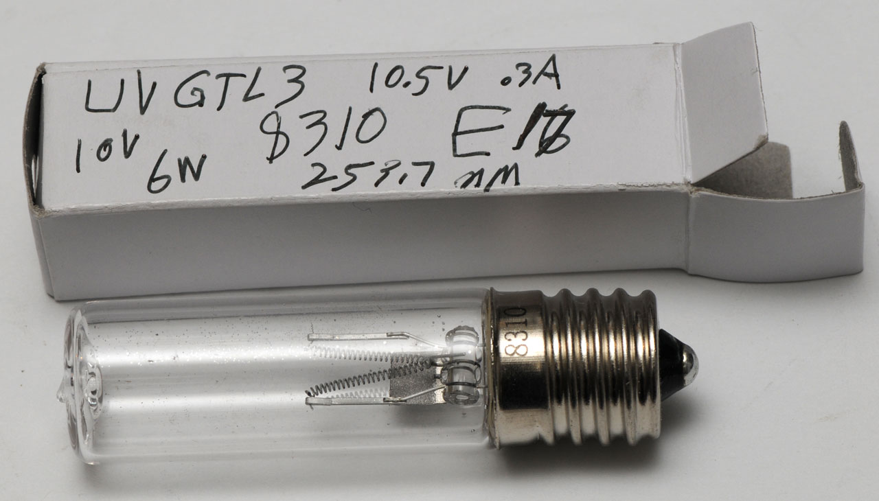
UV Lamp
UV Lamp UVGTL3 8310 E17 Edison base
10.5 V 0.3A 253.7 nm
I think the 6 Watt mark on the box is my typo and should have been
0.6 Watt. i.e. 10V @ 0.3 A is 3 Watts input so the UV output
will be way down from that, such as 0.6 Watts.

This is not Wood's glass (
Wiki)
since it appears clear.
This portable instrument was made to compare the actual
reflectance of things on the ground with satellite data from
Landsat or SPOT satellites by using different filters.
Covers roughly 0.5 to 1.1 micron wavelengths.
AN/UAS-4 Infrared Surveillance System
Uses filters to make multi spectral images.
Covers roughly 0.4 to 30,000 micron wavelengths.
Mims Twilight Photometer (Wiki)
Build a
Twilight Photometer to Detect Stratospheric Particles,
Forrest M. Mims III, 2015 - no lens, 660 or 880 LED, TLC271BIP
Op amp w/DIP pin-2 in the air (TLV9101
replacement?)
Bulletin of the American Meteorological Society: Tropopause
Height Inferred from Twilight Photometry, 2024 -
.Facebook -
Thorlabs
1" Lens Tubes - SM1L40 (1" x 4"),
1050nm IR LED w/o heat sink ($10 eBay). Better results than
shorter wavelength LEDs.
Onset
MX1105 4-Channel, 16 bit, Analog input data logger
YouTube: Here's a
1000 year old experiment, 2:49 - time from sunset till
twilight ends allows calculating the height of the atmosphere
A Radiosonde Thermal Sensor Technique for Measurement of
Atmospheric Turbulence (19750008971.pdf),
Jack L. Bufton, Goddard, Feb 1975 - Includes half meter telescopic
method that look at a star.
Related
Lights
Optics
Optical Spectrum Analyzers
HP 8702B Lightwave Component Analyzer,
Electro Optical Network Analyzer
Links
Back to Brooke's Products
for Sale, Astronomy,
CCD Astronomy, Binoculars,
Optics, Military
Information, Home page
page created 9 July 2007.