LED
© Brooke Clarke 2000 -2024
Circuits
Light Units
Flashlight Design
Filament LED
High Brightness LED
AA Battery
9Volt Battery
Lamina Atlas 7 Watt
Task
Light
E10 Base LED
LED as a Light Sensor
Flashers
Origami LED Kit
Blocking Oscillator - Joule
Thief seperate web page
Single Use Camera Flash
Blocking Oscillator
Joule Thief
Neon Blinkers
Speed Test
White - Phosphors
White - Red, Green, Blue
Numbers & Characters
Flipping Dot
IR USB Toy
XyloBand
Firefly
Links
Seperate web page for Lights
& Electro-Optical Gadgets & Flashlights patents and DIY info
Light Units
There are a number of ways of
measuring the light output from a lamp, LED, etc.
Candela (was:
Candlepower)
Is a measure of the luminance over
some area. For example a sheet of paper is made
translucent by soaking it with oil. On one side is a
candle made to a specification and burning at the specified
rate. On the other side of the paper is a light
source. By moving the light source toward or away from the
paper a location will be found where the two sources are equal
in brightness as seen by your eye. By measuring the
disance from the light source to the paper it's luminance can be
computed based on the inverse square law.
If the light source was another identical candle then it would
be the same distance from the paper. But if a reflector
was on the light source candle it could be moved further
away. The light output from the T series LEDs is specified
in milli candelas. A bright white LED running at 20 ma
might be rated 10,000 mCd but only over a very narrow angle.
Lumens
Are a measure of the total visible
light in all directions. For example a 100 Watt light bulb
in the U.S. (115 VAC) puts out about 1700 Lumens.
Lumens per Watt
A measure of how efficiently a
lamp converts power into visible light is Lumens/Watt. For
the 100 Watt bulb that's about 17 Lumens per watt. Since
power in equals power out the total power radiated from a lamp
is the same as the power put in. Most of the power out of
electrical lamps is at non visible wavelengths, like heat.
City governments or businesses are very concerned with Lumens
per Watt since they pay the electrical bill. This is also
important for battery powered items like flashlights since it
puts an upper limit on the run time.
Here are some values for reference:
Description
|
L/W
|
| Edison's
first lamp |
1.4 |
Edison's
production carbon fil lamps3
|
3
|
| Edison's
prod. tungsten fil lamps4 |
8
|
|
Infrared lamps |
6-9 |
|
Incandescent lamps |
10-40 |
| 1 watt
warm White (3300 K) LumiLED |
20 |
| 1 watt
cold White (6500 K) LumiLED |
46 |
|
Fluorescent lamps |
35-100 |
| Mercury1 lamps |
50-60 |
HID2
|
70
|
| Metal
Halide lamps |
80-125 |
| High
Pressure Sodium lamps |
100-140 |
Note 1 - All fluorescent lights, both conventional and compact use
Mercury.
Note 2 - May contain Mercury
Note 3 - The most popular carbon filament lamp was the 16 candle
power size that consumed about 60 watts and provided about 200
lumens. The smallest line powered lamp was the 8 CP that
used about 25 watts and provided about 100 lumens.
Note 4 - The Tungsten filament lamps were made in 20, 32, 48, 80
and 200 CP (250, 400, 600, 1,000 & 2,500 lumen) sizes for
mains power.
So a LED based lamp for general
illumination needs to put out 100 to 200 lumens. If the
L/W is 20 (warm white) then it takes 5 to 10 LEDs to make a
useable lamp.
The L/W goes up as the current is turned down on modern LEDs,
but then the cost of final lamp goes way up since many LEDs are
needed.
Flashlight Design
Many of the flashlight sellers
make inflated claims about the brightness of their
product. It's probably best to ignore any claim made by
the seller and instead look for a review that has some type of
comparison testing. Instead of using oiled paper (see
above) you can just shine two lights on a white
wall side by side and compare them.

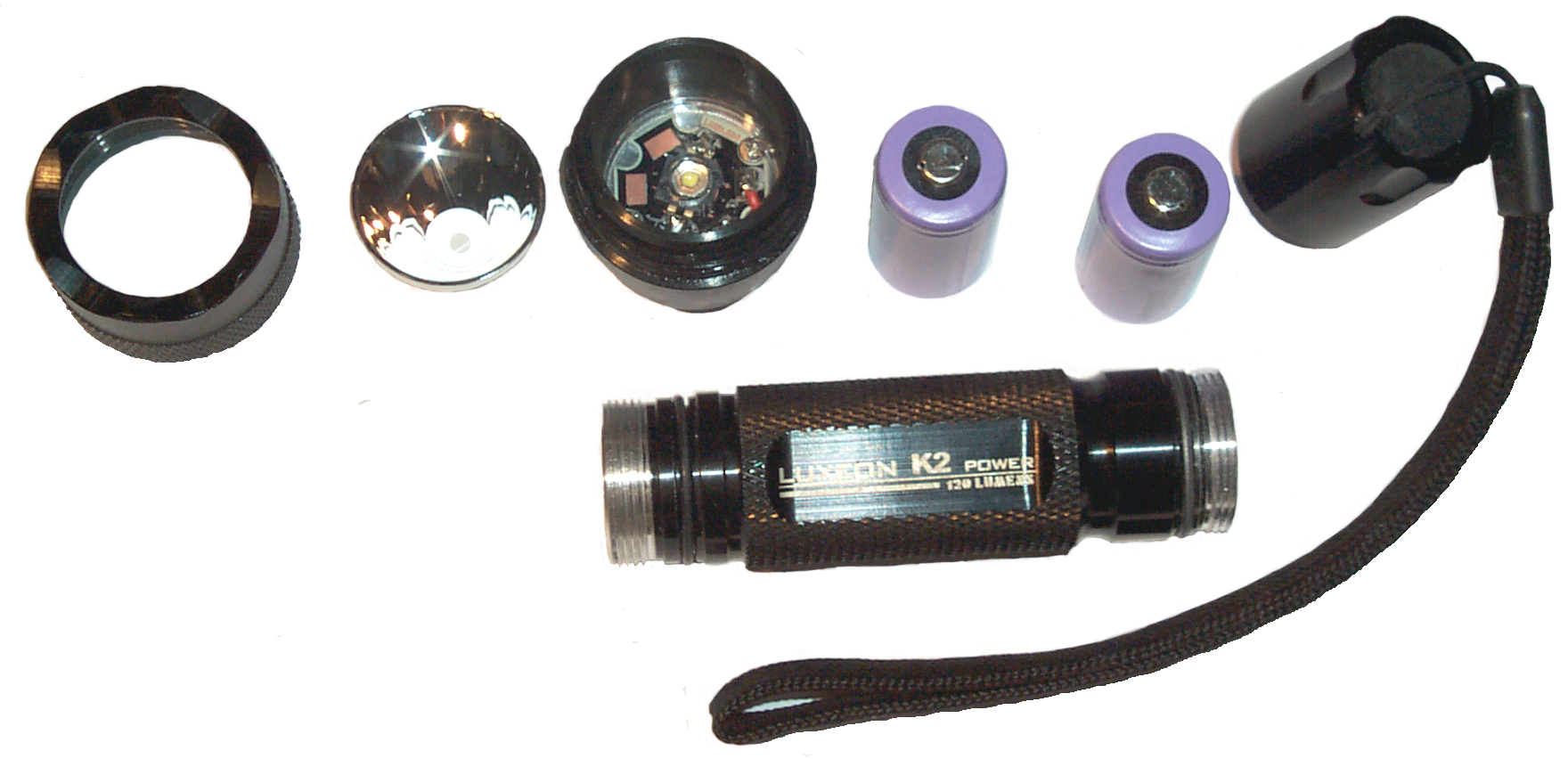
The main problem I've found is the high
amount of wasted power. For example the Made in China
"Luxeon K2 Power 120 Lumens" flashlight that runs on two LIR123A
cells. This is a cheap flashlight that uses a 4.2 Ohm
resistor to set the LED current. Since two 3.4 Volt
batteries are being used and the voltage drop on the LED is
about 3.85 volts that leaves 2.95 volts or 700 ma or about 2
Watts to dissipate in the resistor and about 2.7 Watts in the
LED for a total nearing 5 watts. This means that after
about 10 minutes this flashlight it too hot to hold.
Lumens per Watt doesn't mean much when you burn power in a
resistor.
The K2 is rated for up to 1.5 Amps (see K2 Drive Currents
below) the
LIR123A
cell is rated to deliver a maximum current of 800 ma where the
K2 puts out 93 Lumens, not 120. These cells are
rated for 400 mAh capacity at 0.2C, i.e. at 0.2 * 400 ma = 80
ma. There is no specification for the 2C discharge
capacity. But the best case is 400 mAh capacity being used
at 700 ma so will last at most 34 minutes.
A step up from a resistor is a regulated current source.
For example the
7135
regulator is used in many flashlights. This is a 300 ma
linear regulator that has a constant current output. A
flashlight might have three of these so by pressing the
"Clickey" switch you get 0, 300, 600 or 900 ma current into the
LED.
The most efficient way is to use a buck type Switching Mode
Power Supply. In this case the input voltage is higher
than the LED voltage (typically in the 3.8 V area). See
the Experiments
below. The reason I
say with an input higher than the LED voltage is because the
capacity of most batteries decreases with increasing
current. For example a common 9 volt battery could be used
to drive a high brightness LED at 350 ma for 1 hour (see
experiment
below) but when a Switching
Mode Power Supply is used between the battery and LED the same
battery would last for about 4.5 hours.
It's possible to use a boost type SMPS with a single cell
battery to drive a high brightness LED. This has the
effect of greatly lowering the capacity of the cell in exchange
for a much smaller light.
It costs more to use a Switching Mode Power Supply and so the
lights are more expensive, but the battery life is much much
better. Unfortunately most of the advertisements don't
tell you if they use a resistor, linear regulator or SMPS type
supply.
7 Nov 2007 - In conclusion I'd say that most (90%?) of the High
Brightness LED flashlights on the market have been designed more
for advertising value than for benefit to the user. It
seems that the information a user would need to know to choose
between the large number of makes and models like the type of
current control (resistor, linear regulator, SMPS) or the
efficiency of the current control, the candela brightness at
some beam width, weight and size are all missing from the ads.
Also See the
Flashlight
Patents page for tube sizes and other construction info.
Filament LED
The Magnetic
Levitating Lamp uses filament LEDs. They are also
used in a number of LED lamps because the have the look and feel
of old fashioned filaments.

|
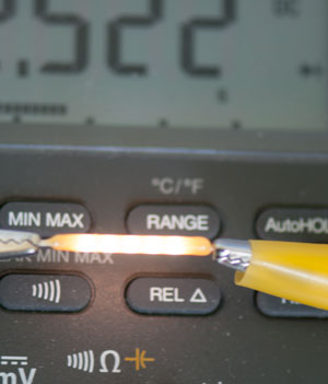
The interesting thing is that this one
turns on with only 1 mA (Fluke 87 DMM
in Diode mode) with a voltage drop of 2.522 V.
This is amazing performance. Normally it takes more
than 3 volts to get anything near a white light from an
LED.
|
 |
With image brightness adjusted to look more
like with eyes.
|
High Brightness LED
Philips
Luxeon aka.
LumiLED are LEDs that run at currents in the 350 to 1,500 ma range
as compared to the common T13/4 type LED that runs at 20 ma.
A white LED may have a forward voltage of 3.2 v and with a current
of .35 amps that's 1.1 Watts most of which is heat that needs to
be dissipated. One way of doing that is to use a special PCB
material that has an aluminum core, but that's an expensive
solution. Another option is to use a copper plug and CPU
thermal epoxy to attach the emitter to the copper.
Oct 2007 - Phillips now has the
Rebel
which is a small
Surface
Mount
Technology LED on a small heat sink. It's designed to
be used on a normal printed circuit board with a pattern of over a
dozen plated through holes nearby to act as the heat sink.
150 deg C junction temp and 350 (80 lumens) to 1,000 ma drive.
Nov 2007 - Some T10 size LED are showing up on eBay. These
appear to be high brightness LEDs packaged in the clear plastic
T10 package. These packages have a built-in lens so the
candela rating is very high. They have special mounting
requirements and heat sink needs, which so far it's not clear how
to meet.
The first generation emitters have a Tjunction max of 120 deg C
and so need more heatsinking than the newer K2 emitters which have
Tjmax of 180 deg C.

12 Feb 2007 -
This is a first generation 1 watt emitter, the LXHL-BW03.
It's a warm white color that is very pleasing, not like the white
that has the excess blue. I have it rubber banded to an
aluminum bracket and the bracket does not get even warm.
0.340 Amps @ 3.15 volts. Note at cold turn on the Vf is 3.26
volts and after running a long time the Vf is 3.25 a drop of 22
mv. The data sheet says -2 mv/deg C so the LED is only
heating 5.5 deg C over ambient.
I have more LumiLEDs on order (3 watt) that run at higher powers
to get a feel for the heat sinking needed.
I have this LED hung off the arm supporting a halogen desk
light. The LumiLED is considerably dimmer than the 50 watt
bulb, but it's adequate for seeing what I need to see and the
color is pleasing.
All the fuss about hermetic storage relates to wave
soldering. If an emitter is left out in the open it can get
moisture inside, then when it's wave soldered it may
explode. But this isn't a problem for hand soldering.
It's not a problem for the "Star" parts that are already solderded
to an aluminum heat sink.
Efficiency is measured in Lumens per Watt. Here are some
numbers for comparison.
Edison's first lamp 1.4 L/W
Infrared lamps 6-9 L/W
Incandescent lamps 10-40 L/W
1 watt warm White (3300 K) LumiLED about 20 L/W
1 watt cold White (6500 K) LumiLED about 46 L/W
Fluorescent lamps 35-100 L/W - all use Mercury
Mercury lamps 50-60 L/W - uses Mercury
Metal Halide lamps 80-125 L/W
High Pressure Sodium lamps 100-140 L/W
Theoretical max for white light 225 L/W
Data sheet values for the cold white (6500K) K2:
K2 Drive Currents
|
350 mA
|
700 mA
|
1 A
|
1.5 A
|
Vf
|
3.42
|
3.6
|
3.72
|
3.85
|
P
|
1.2 W
|
2.5 W
|
3.7 W
|
5.8 W
|
L
|
55
|
93
|
120
|
140
|
L/W
|
46
|
37
|
32
|
24
|
Lumens decrease 10% for each 50 deg C rise in temp.
There is a tradeoff related to what current is used to drive a
K-2. At the lower currents you get higher efficiency (L/W)
but less total light output.
At higher currents you get more light. But heat sinking
comes into play at the higher currents.
Model
|
Package
|
Color
|
Patrn
|
V
|
I
|
W
|
V/I
|
LXHL-BW03
note1
|
emitter
|
wrmWht |
BW
|
3.29
|
350
|
1.1
|
9.4
|
| LXHL-MWGC
note1 |
Star
|
wrmWht
|
BW
|
3.29
|
350
|
1.1
|
9.4
|
| LXHL-NWG8
note1 |
Star-O
|
wrmWht
|
10
deg
|
3.29
|
350
|
1.1
|
9.4
|
LXK2-PW14-U00
|
emitter |
Wht
|
Lamb
|
3.58
|
10002
|
3.6
|
3.58
|
LXK2-PR14-Q00
|
emitter |
RlBlu
|
Lamb |
3.95
|
10003
|
4.0
|
3.95
|
note
1 - these 3 are all the same warm White 1 Watt
emitter in 3 different packages.
The emitter is the raw LED. The star is an emitter mounted
to a PCB with an aluminum layer. The Star-O has a small
parabolic reflector.
note
2 - the power supply
has a 1 Amp current limit so did not test at 1.5 Amps. The
LEd lights with a current that appears to be under 1 ma (below the
resolution of the Agilent E3617A power supply). As the
current is increased the light output increases (see Data Sheet
DS51 Fig 11 on pg 15) but the slope is flattening slightly as the
current increases. 3.76 volts @ 1 Amp at turn on, then 3.40
v after some time. With -2 mv/deg C the temperature is going
up about 18 deg c or 5 deg C/watt.
note
3 - the voltage drops to 3.77 after a minute or so.
meaning 9 deg C temp rise or 2.25 deg C/Watt. I used a new
bracket and applied a good size gob of silicon grease to this
one.
19 Feb 2007 - First look at the LM3402 driving a LumiLED LXK2-PW14
at 350 ma (the K2 is good up to 1.5 amps and is very bright @ 350,
but can put out more light at 1.5 Amps). So the LM3402 can
drive both types.
The current in the LED is regulated at 354 ma and the Vf is 3.046
so the power is constant at 1.078 watts.
Efficiency = 1.078/Power In
Vin
v
|
Iin
ma
|
Eff
%
|
5.27
|
243
|
841
|
6
|
223
|
81
|
8
|
169
|
80
|
10
|
131
|
82
|
12
|
114
|
79
|
14
|
98
|
79
|
16
|
88
|
76
|
18
|
79
|
76
|
20
|
71
|
76
|
22
|
65
|
75
|
24
|
60
|
75
|
26
|
56
|
74
|
28
|
52
|
74
|
30
|
49
|
73
|
32
|
46
|
73
|
34
|
44
|
72
|
36
|
41
|
73
|
Note
1 - At low input voltages the regulator is not
putting out the full voltage and so the LED is not getting the
constant power it does for higher input voltages. So the
efficiency calculation is wrong (looks better than it would if the
actual LED power was measured).
Note that driving a single LED is the lowest efficiency because
most of the loss is independent of the drive voltage because of
the constant current. So adding more LEDs improves the
efficiency.
Now two K2 LEDs in series LXK2-PW14 (white) & LXK2-PR14 (royal
blue).
The current is the same as before 354 ma but the voltage is now
6.48 for a power of 2.294 watts.
Vin
v
|
Iin
ma
|
Eff
%
|
5.29
|
2
|
note1 |
6
|
5
|
note1 |
8
|
45
|
note1 |
10
|
174
|
note1
|
12
|
205
|
93
|
14
|
178
|
92
|
16
|
158
|
91
|
18
|
142
|
90
|
20
|
128
|
90
|
22
|
118
|
88
|
24
|
109
|
88
|
26
|
101
|
87
|
28
|
94
|
87
|
30
|
89
|
86
|
32
|
84
|
85
|
34
|
80
|
84
|
36
|
76
|
84
|
note1 - although the LEDs will light at voltages below 12 volts,
they are not as bright as at higher voltages so it's difficult to
calculate the efficiency.
Low Current Operation
I don't have a good way to measure brightness so I'll describe in
words what I've observed. The high power LED seem to work
down to very low currents (below the range of the current meter on
the HP E3617A power supply (1 ma). The efficiency gets
better as the current is lowered. So if you run a 1 Watt
LumiLED at 20 ma, it will put out more light than a 5mm type high
brightness white LED. The data sheet indicates about 46
lumens/watt which is maybe twice as good as the high brightness
5mm LEDs. Note that 5mm LEDs typically have a lens that
focuses the light into a 15 deg beam so it's hard to compare to an
emitter that's putting out a 120 deg beam.
AA Battery
20 Feb 2007 - Normally you would not use AA batteries to
power a LumiLED that draws 350 ma. This is because at that
current the batteries would last between 90 minutes and a few
hours. Note that this is the case independent of the number
of series batteries when a linear voltage regulator, like the
LM317, is used. BUT it is what done in most of the cheap LED
flashlights.
On the other hand with a Switching Mode Power Supply (SMPS) the
power drawn from the battery pack remains constant, but the
current changes as the pack voltage changes (either due to the
number of cells in the pack or due to discharge). So if 10
AA cells are used to drive a single LumiLED at 350 ma the battery
current is 100 ma. The Constant Current Performance chart on
the Energizer E91 data sheet shows a run time of 15 to 30 hours
for a 100 ma load.
If the Constant Power Performance chart is used and the power from
the 10 AA battery pack (13.8 V * 100 ma) 1.38 watts and divide by
10 cells or 0.138 watts per cell. The run time ranges from
12 to 20 hours.
Now looking at the Energizer L91 data sheet. At 350 ma
constant current the run time is 8 hours and at 100 ma constant
current is 30 hours.
But now looking at 1.38 watts Constant Power the run time is more
like 40 Hours. The L91 was designed to supply SMPS supplies
where the current increases as the battery discharges.
On the E91 Constant Current curve note that the slope gets steeper
above 100 ma. A change in slope represents a change in amp
hour capacity. So you get more amp hours when running at or
below 100 ma.
9 Volt Battery
The
energizer 9 volt Alkaline battery (
522) is rated
for 4.5 hours at 100 ma. and maybe 1 hour at 350 ma. So by
using a SMPS the battery lasts more than 4 times longer.
It's very hard to take a photo of a 1 watt LED operating becasue
it makes a lot of light. This photo gives an idea of the
relative brightness but is not in focus.
Single Cell Battery
There are applications where the 1 watt LED needs to be powered by
a single cell. The cell voltage varies with the chemistry
from 1.2 v or Ni-MH to 3.4 v for rechargable lithium. There
are SMPS that are designed to raise the voltage but they do it by
drawing more current from the battery than the load
consumes. As the current drawn from a battery increases the
amp hour capacity decreases. This is why the battery data
sheets have discharge curves (constant current, constant
resistance and constant power are the common ones). This
method of powering a 1 watt LED works, but at the expense of less
battery capacity.
Observations
When any of these, except the Star-O which had the emitter hidden,
are used in a way where you can directly see the emitter it's not
comfortable because of the brightness. The output of the
Royal Blue emitter is specified as about half a milliwatt and all
the other emitters are specified in lumens (the Star-O in
candelas) so it's hard to compare the specs. To my eye the
brightest by far is the PW14 emitter.
So far Philips has not offered the K2 in any of the "Star"
packages which mount the emitter on a PCB that has an aluminum
core that acts as a heat sink. One of the reasons for this
may be that the max temperature on the K2 emitters is much higher
than on the other types allowing it to be mounted on top of a
normal FR4 PCB.
Power Supply
The high brightness LEDs are best driven by a current
source. There are a number of different ways to do that.
- Cheap and dirty is to use batteries that have enough
internal resistance to limit the current to a safe level.
- Use a linear regulator, like the LM317, and replace the top
voltage set resistor with the LED(s) and choose the bottom
voltage set resistor to be Vref/Iled. The problem with
this is that you are dissipating a lot of power in the 317 and
if near the LED the heat combines.
- Use a Switching Mode Power Supply. This has a big
advantage in terms of efficiency. If the source is a
battery, like the BA-5590 family
that has 12 or 24 volt capability then the SMPS is working in
the buck mode where the input current is lower than the LED
current by about the ratio of the voltages. This not
only is efficient but also extends the battery life from what
it would have been with the 317 because the battery life
measured in Watt Hours increases as the load current
decreases. Note that the SMPS can drive a series string
of LED so long as the total LED voltage is lower than the
input voltage less the peak ripple plus a little.
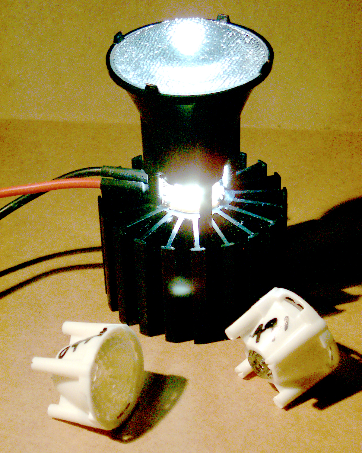
Lamina Atlas 7 Watt
WARNING
White LEDs really are a blue LED that illuminates a
phosphor. The light contains a lot of UV and can
burn your eye just like looking into an arc
welder.
It's been 4 days and I'm no longer suffering like I was
when this was written. It may be that it's just
the point source visible light that's causing the
problem. I'm looking into what caused it.
|

The company has many patents going way back
in the area of ceramic circuits like used for microwave
components. The key technology here is the ability to get a
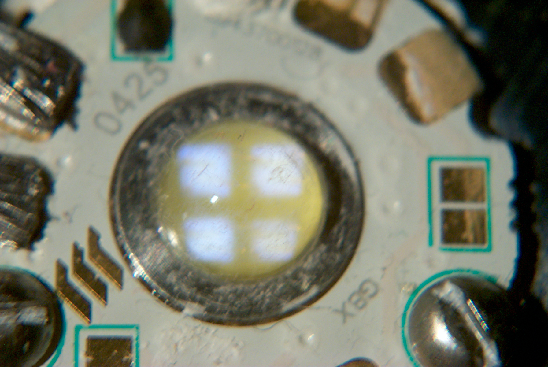
good heat path through an insulator. The disk has four LED
chips mounted in a square pattern. At 1 amp forward the Vf
is 7.68 Volts so the LEDs must be wired in a series parallel
combination. Part of the Atlas family is a specialized
extruded aluminum finned heat sink that comes in lengths of 0.75
or 1.5 inches, this one is the 1.5" version.
This Light Engine is the Lamina NT-42D1-0425 Warm White (3000 K)
rated for 8.2 Volts at 1.05 Amps (8.6 Watts input) and 162 lumens
out. They make brighter cold white (5000 K) LED, but I like
the feel of the warm light. The data sheets have quite a bit
of data at 350, 700 and 1000 ma.
The photo at left was taken with 7.68 volts at 1 amp (7.68
Watts). I was trying the three optics, wide, medium and
narrow by sitting them on the LED+heatsink and with the spot beam
little light was coming from the optic lens toward the camera, but
the direct leakage from the LED was so bright that the flash did
not fire and the image came out mostly black. I've tweaked
it in photoshop to make it viewable. The 40° and 30° small
optics are made by
Fraen
and I suspect so is the 10° spot optic. Fraen makes
optics that match
most of the high power LEDs. OP-4LN2-0492 10 deg beam
sitting by gravity on lamp-heat sink, OP-4FW1-0442 30
deg & OP-4FW1-0441 45 deg beam optics in
front. These are a solid lens in a holder.
I'm using
Wakefield 126 (
accessories.pdf
1.3 MB) Thermal Joint Compound, not the 120 Lamina
recommends. The way I read the specs this is twice as good
when first installed and even better after the 120 has aged for 6
months.
Since the disk with the LED needs to be attached to the heatsink
using thermal grease and held in place with screws you can not
attach the optic until that's done. So to make a task light
some sort of can needs to be added to what you see in the photo.

There are four LEDs inside the Lamina LED assembly. I've had
it out in my office area and you can see that it's covered with
dust. In a real world application the LED assembly needs to
be in a dust proof environment
Note the use of 2-56 Round Head screws since they have a smaller
head diameter than pan heads.
Photo taken with about 4.8 Volts and less than 1 ma current
(Agilent E3617A display .000 Amp).
LumiLED
-
Cree - no
warm white
Seoul
Semiconductor - P4 - broken web pages 16 Feb 2007
Lamina - LEDs aimed
at use in buildings
 If
you look at the back of the optic you can see the clear plastic
part that has a hemispherical hole that fits over the LED
silicon. The optic is actually seated on the silicon and
can be rocked a little. Drilling holes in the heat sink
would serve no purpose. The intended mounting scheme is to
place the application PCB over the top of the LED star board
with large via holes in the PCB that line up with the pads on
the star board then solder them toghther. Then the
optic pins, which go completly through the application PCB can
be mushroomed using a hot iron. But that makes for an
akward assembly operation thereafter.
If
you look at the back of the optic you can see the clear plastic
part that has a hemispherical hole that fits over the LED
silicon. The optic is actually seated on the silicon and
can be rocked a little. Drilling holes in the heat sink
would serve no purpose. The intended mounting scheme is to
place the application PCB over the top of the LED star board
with large via holes in the PCB that line up with the pads on
the star board then solder them toghther. Then the
optic pins, which go completly through the application PCB can
be mushroomed using a hot iron. But that makes for an
akward assembly operation thereafter.
A better solution is to put the star LED board and optic into a
aluminum can from the front.
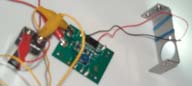
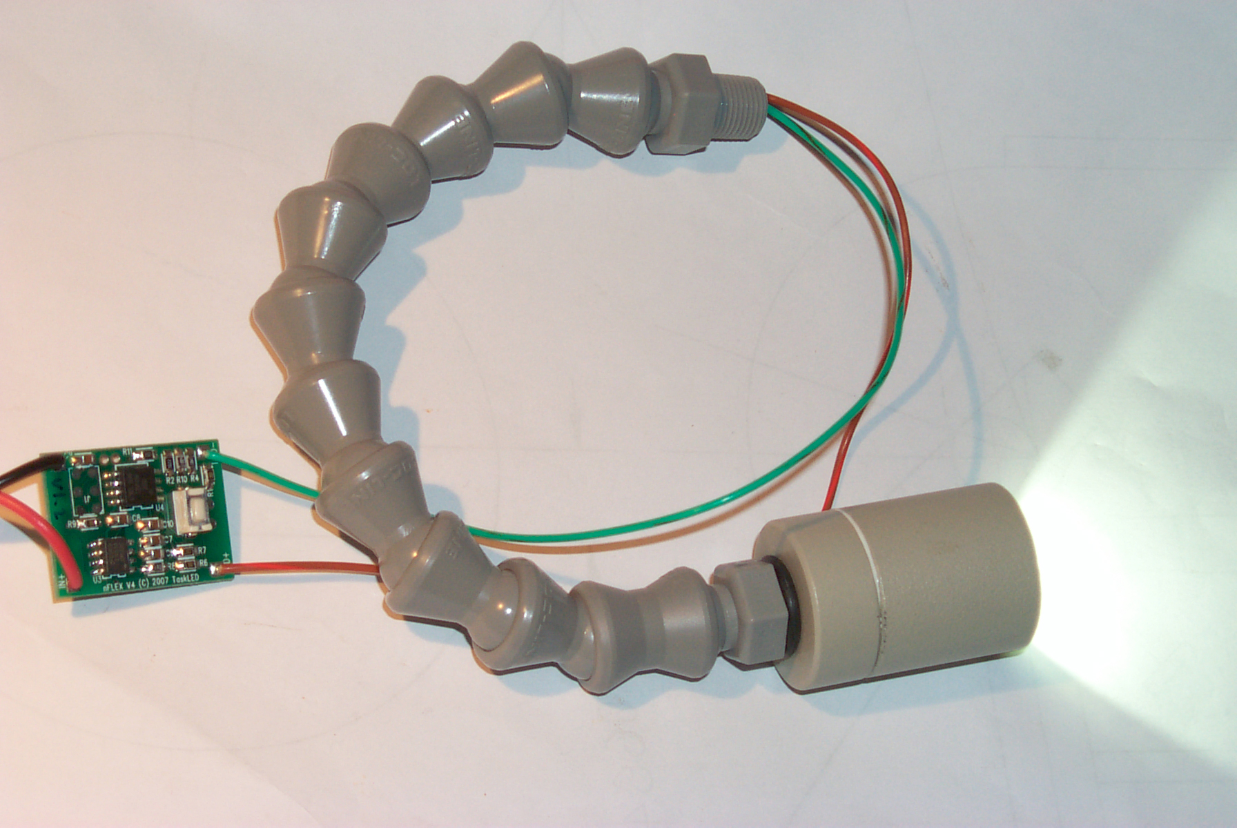
Task Light
 The parts shown are
available as an assembled board that has a combined buck Switching
Mode Power Supply and a micro controller to allow programming the
drive current and a number of handy user functions and the assembled
LED head on a 6" length of Loc-Line.
Called the FlexiLED
Task Light. There are slightly different versions with
the micro controller commands suited for fixed, portable or
bicycle use.
The parts shown are
available as an assembled board that has a combined buck Switching
Mode Power Supply and a micro controller to allow programming the
drive current and a number of handy user functions and the assembled
LED head on a 6" length of Loc-Line.
Called the FlexiLED
Task Light. There are slightly different versions with
the micro controller commands suited for fixed, portable or
bicycle use.
The Loc-Line is stiff enough to hold the head where you point
it. Much superior to the old flex metal goosenecks that had a
lot of built-in spring.
The relative scale of the Task Light and the Lamina Atlas in the
above photo is close to accurate. The Task Light head is about
1" dia and the Lamina 10 deg optic is about 2" dia.
There are a number of settings that relate to batteries such as
warning when the battery voltage goes below some value or an auto
off mode that will turn the light off after some time period.
To program it you push the white button visible on the PCB (or
connect your own button to the supplied thru holes) and the LED will
blink to acknowledge the commands. Not the most user
friendly interface, but just the thing for a bicycle or other
application where once setup very simple button presses suffice.
E10 Base LED 1 Watt

T10-WHP from Super Bright
LEDs.
I got this as a universal lamp for testing various flashights.
The base is Edison 10 mm (E10) the standard for all the early flash
lights. Specified to be 1 watt with a 2.8 to 12 Volt input
range, 35 Lumen 120 degree beam.
E10 based lamps do not have pre focused filaments and many
flashlights have a way to change the axial position of the lamp to
find focus. That's the next test scheduled for this lamp.
But didn't expect it to be so high tech. Here is some I-V-P
data:
V
|
2.29a
|
2.5a
|
3
|
4
|
5
|
6
|
7
|
8
|
9
|
10
|
11
|
12
|
I ma
|
4
|
147
|
434
|
272
|
200
|
160
|
134
|
117
|
103
|
94
|
86
|
79
|
P watt
|
0.01
|
.037
|
1.30
|
1.09
|
1.00
|
0.96
|
0.94
|
0.94
|
0.93
|
0.94
|
0.95
|
0.95
|
Note 1 for voltages between 2.something and 3 the brightness is
increasing and constant for higher voltages.
This type of load curve incicates a Switching Mode Power Supply, not
a simple resistor or linear voltage regulator.
And it all fits in a very small space. How did they do
it? let me know. Although
the Joule
Thief circuit will fit this space I doubt it would supply 1
watt.
LED as a Light Sensor

When light falls
on the silicon diode in a LED it acts like a small solar cell
generating electricity. So it can be used as a light
sensor.
Pointing the Radio Shack 276-143 IR (940 nm) LED at the Sun shows
924 mv (Fluke 87 DMM 10 M Ohm input). But when the meter is
configured to measure current there is no output (i.e. this solar
panel will not deliver any power). The output is about 930
mv when the LED is placed 1/2" below the glass of a halogen desk
lamp. When held under my desk the output is more like 90 mv,
so there's some weak IR bouncing around inside coming from
sunlight in the window.
When the IR Filter from a
SDU-5/E Strobe
Light is placed between the halogen desk light and the LED
the output drops only a few percent. Note that this filter
blocks all visable light from the strobe so well that when the
strobe is running and you place the filter right at your eye you
can not see anything.
Connecting the LED to a Fluke 87 DMM in DCV mode and pointing the
LED at my eye while it's touching my reading glasses to help hold
it steady, then turning on Min Max mode. When looking left
or right there are beeps indicating the the LED is seeing my open
eye movements.
Repeating the test with both eyes closed also causes a beep or two
indicating that it's working but not as sensitive.
See the
Electro-Optical Gadgets
page for a very sensitive way to measure light using an LED and a
PIC microcontroller.
LED Drive Circuits
ELM - White LED Head
Lamp - a 2 transistor 2 AA circuit Pocket LED
Light a 1 AA 1 transistor blocking oscillator
KnurdLight PIC Example
Project - This is the 3rd generation of a 4 white LED hat brim
light packaged in a waterproof tupperware box a little larger than
the 2 AA cells that will power it for about 20 hours. Full
documentation on line.
LED Flashers
Interesting observation about a home made bicycle safety
flasher:
" . . . An interesting problem occurred when I was
designing it. I am somewhat prone to migraines. The
day I was first working on it, I had it set up with 50mS
continuous pulses, which would light each LED at about 5 Hz with
no rest between pulses. The LEDs are extremely bright up
close, they hurt the eyes with a fresh battery. I found
the effect of the continuous hammering of the 5 Hz light pulses
mesmerizing, and I found myself staring at it blankly, even
hypnotically. Later that day I got a humongous migraine.
The next day, shaken from a night of pain, I turned on the
headlamp again and realized it was stimulating another
head-pounding headache. I changed to the 900mS
between pulses after that, and it never had the same effect on
my aching head again. Maybe I have discovered the elusive
nonlethal weapon?" -Piclist-
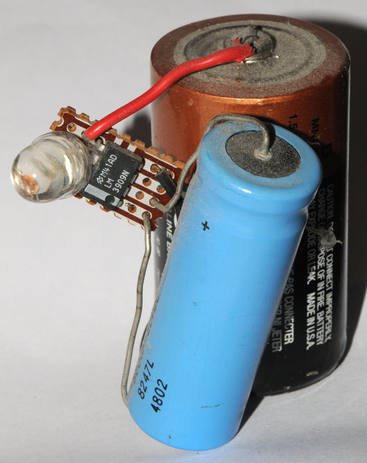
LM3909
LM3909 D-cell, Jumbo LED, 500 uF
50V Cap
This now obsolete chip when
combined with an external capacitor, 1.5V battery and an LED
will flash the LED for a very long time (years). The data
sheet suggested that the battery might even last longer on the
flasher than it would just sittingon the shelf. I think
they were used in emergency flashlights, like on commercial
aircraft to let you know the batteries were OK.
The LM3909 will not flash the newer color LEds, like a white or
blue since thier voltage is higher than a red LED.
Replacement
For
The LM3909 LED Flasher / Oscillator -
1.5
Volt
LED
Flashers -
Futurlec -
New Old
Stock LM3909
Origami Cat LED Kit
Requires cutting into square and punching three round holes
(can use LED to enlarge a slit).
Folding so that ..... is visible after fold, or so that --------
is hidden after folding.
Bend LED leads about in half so they are all within the battery
diameter.
Install LED and battery inside and make (9) fold.
Blocking Oscillator
Blocking Oscillator w/o LED
If a Zener diode is connected between the Base and Emitter (cathode
to emitter) it will clamp the base voltage to the Zener voltage
protecting the E-B junction from breakdown.
Now if the LED is disconnected and the supply is at 1.0 Volts the
collector waveform is a voltage spike about 82 volts high and 200 ns
wide at 40 volts. The duty cycle is small.
Terminology
Blocking Oscillator - uses a dual winding transformer to form a very
low cost oscillator circuit. Operation may depend on the
saturation current of the drive transistor and/or core saturation of
the transformer. Typically no air gap in transformer. A
secondary winding can be added (three windings total) to provide a
high voltage output. Vout = (Vbat - Vces) * Ns/Np The
voltage step up is due to the transformer winding ratios. The
magnetic circuit has minimal energy storage. Low power
circuit. Used in throwaway cameras for the strobe high voltage
generation circuit.
Flyback Oscillator - the primary of a transformer is charged up then
drive is turned off allowing the collapsing filed to generate a high
voltage in the secondary. The transformer has a small
controlled air gap. The magnetic circuit must store all the
power needed for the output. Medium power circuit.
Inverter - A pair of transistors drive the primary of a
transformer. The magnetic circuit has minimal energy
storage (no air gap). The duty cycle is very close to
50%. Can be high power circuit.
By adding a very narrow air gap the performance is enhanced by
greatly lowering the residual magnetism. This eliminates large
current spikes at turn on. These gaps are made by lapping the
two faces to be as flat and smooth as possible.
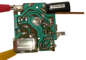
Single Use Camera Flash Blocking Oscillator
This circuit can easily be removed from a single use Kodak flash
camera. It runs from a single AA battery.
|
|
The
button in the center of the PCB starts the flash charge
cycle.
|
The two
sheet metal parts on the right go to the shutter
switch.
Notice the Neon bulb at the upper right is on.
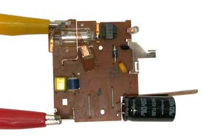
|
The 120 uF 330 V cap has a little more than 300 Volts after a the
charge cycle.
The energy stored in the capacitor is 1/2 * C * V*V (Watt Seconds) =
0.5 * 120e-6 * 300 * 300 = 5.4 Joule (1 Joule = 1 Watt Second)
The circuit draws just over 1 amp and the current tapers down to 1
mA in about 17 seconds. The Neon lamp glows but does not blink
when the charge cycle is done.
For driving the synchronizer in a Western Union Self Winding Clock the current is controlled
by a series resistor. The time constant is L/R so for a 100 ma
drive and 300 Volts the resistor would be about 3 k Ohms. If
the synchronizer coil was 1 Henry (a very high estimate) then the
time constant would be 1/3000 or about 330 micro seconds.
That's very fast compared to the operating times of mechanical
systems and fast compared to the thermal time constant of the
coil. As the resistor is made smaller two things happen.
The time constant gets longer, allowing more time for the mechanical
movement, and the current increases, which is probably OK until it
gets near the wire exploding value. Note that wire heating
will not be a problem since the synchronizer is pulsed only once per
hour.
Don's Xenon Flash and Strobe Page - Strobe
Lights
and Design Guidelines, Useful Circuits, and Schematics - has
info on similar circuits
Sam's Strobe
FAQ - scroll the page, the links go to other pages
Blocking oscillators are used in many applications because they are
simple (low cost, small size, light weight, etc.).
They can be free running or triggered. When triggered the
output is a pulse rather than a spike and the pulse width or delay
may be the key parameter and/or the power in the pulse. There
are various modes of operation:
- Linear - really a relaxation oscillator
A capacitor driven with a current has a linear voltage ramp or
an inductor driven with a constant voltage has a linear current
ramp.
Either of these can be used to generate ramps or relaxation
oscillators.
- Active device saturation
Here the ramp continues until the active device saturates
- Magnetic core saturation
Here the ramp continues until the magnetic device saturates
- Voltage Breakdown
Here a capicator ramps until there is voltage breakdown in a
Neon tube or other voltage clamping device.
a type of relaxation oscillator
2211852
Blocking Oscillator Apparatus, Max Geiger (Telefunken), Aug 20,
1940, 331/146 ; 336/182; 336/185 -
has good description of why
windings are not done layer by layer when low capacity is
important
2816230 Blocking Oscillator
Circuit, Lindsay, Dec 10 1957,
331/112 ; 331/146-
transistor
2857518 Transistor Blocking Oscillator, Robert C. Reed (North
American Aviation), Oct 21, 1958,
331/112 ; 331/146;
331/183 -
triggered power pulse generator
2894212 Blocking Oscillator, Dalton L. Knauss (Hoffman
Elec), Jul 7, 1959,
331/148 ; 327/191; 327/596 -
saturable core mentioned
sharp rise and fall times
2976489 Blocking Oscillator, Maurice R. Bums (North American
Aviation), Mar 21, 1961,
327/267 ; 331/149 -
tube circuit used to generate a
precise time delay
2988709 Transistor Blocking Oscillator for Telemetring, Herbert K.
Janssen, Jun 13 1961,
331/112 ; 324/711; 331/65; 331/66-
used to generate audio frequency
sawtooth whose frequency is proportional to input resistance
3005158 Core Saturation Blocking Oscillator, Robert J. Spinrad
(AEC), Oct 17, 1961,
327/177 ; 327/191; 331/105;
331/112; 331/113R; 331/148; 331/149; 336/110; 336/155;
340/870.24; 340/870.33; 377/96-
Equations for active device saturation modes and core saturation
modes
uses a permanent magent in the transformer to control the
magnetic bias and hence the pulse width
References:
2605423 Oscillator, Leon Bess (Navy), Jul 29, 1952,
331/146
; 331/148 - linear sawtooth type, 2 triodes
2717961 Frequency Division, Charies W. Johnstone (Navy), Sep 13,
1955,
331/149 ; 331/146; 331/148; 377/96-
2740047 Electric Pulse Generators, Alan J Bayliss (GE), Mar 27,
1956,
331/51 ; 327/231; 331/148; 377/96- divide by 10
tubes
2838669 Counting Network, JR Horsch (GE), Jan 10, 1958,
377/97
; 327/100; 331/148; 331/149; 331/177R; 365/206-
core saturation used to regulate
input pulses
2846581 Transistor Pulse Generator Circuit, Hendrik Volkers
(Philips), Aug 5 1958,
331/112 ; 331/148; 363/18- more
reliable transistor osc starting
2886706 Blocking Oscillator Pulse Width Control, SC Rogers (Bell
Labs), May 12, 1959,
331/112 ; 331/148-
concerned with overcoming
variations due to transistor parameter variations when using
transistor saturation
2903677 Timing Track Recording Device (for mag drum clock), D.
L. CURTIS (Hughes), Sep 8 1959, -
uses center tapped mag head as
transformer of blocking osc a key idea is recording a clock
signal on the drum rather than using a toothed wheel or trying
to use an external crystal
2908870 Generation of Very Short Microwave Pulses, Clyde D.
Hardin (Army), Oct 13 1959,
331/87 ; 331/148; 342/202 -
tube type blocking oscillator
directly drives magnatron for high resolution radar\
bifilar wound ferrite toriod with low inductance (low
capactance)
output X-band 10 ns pulses 150 Watts (800 Volt drive
pulse impedance matched to the magnatron)
2964716 Displacement to Frequency Converter, N Berman (United
Aircraft), Dec 13 1960,
331/113A ; 331/181-
Angular position of an input
shaft changes magnetic properties of core changing frequency
of oscillator
similar oscillator topology to the
Royer
inverter
oscillator, i.e. balanced design multiple feedback
windings.
3185939 Generator with Blocking Oscillator Controls, John I. Moss,
May 25, 1965,
331/52 ; 331/112; 331/172; 331/47; 361/203;
607/71- muscle stimulator
Neon Blinkers
Before semiconductors Neon lamps
were used to make blinking lights Neon blinkers were the thing to
have. I had one in the early 1960s on the shelf above my
work bench. It consisted of a 90 Volt dry battery and series
resistor and a cap in parallel with a neon bulb. It would
blink about once every couple of seconds. It was on all the
time (today you might say it was on 24/7) for some number of
years. I'd bet a dollar to a donut that the designers of the
LM3909 had one of these.
Next to the Neon Blinker was a glass jar with the label
"IITYWYPAPITJ". When visitors came to my room they usually
would ask "What is that blinking light?" and my response was: if
it tell you will you put a penny in the jar.
Starting late September on the PIC List there has been an on going
discussion about how to make these based on problems encountered
with the lamps not going out, but instead staying on. Once
this happens the cap can not charge up and it quits blinking.
One solution to this is presented in U.S. patent 2714692 (
USPTO,
Pat2PDF,
Google)
Portable Electronic Identification Light, W.D. Nupp, J.M. Rosen,
Aug 2 1955,
315/232 ; 315/241R; 315/245; 340/908.
I have redrawn the circuit (without changing any connections) to
make it clearer and reduce the file size.
The main circuit is B charging C1 through R1 causing the 3 Watt
Neon bulb PL1 to flash about once per second. But PL1 does
not self extinguish.
So the 1/4 watt neon bulb PL2 (which does self extinguish) is
driven at about 10 CPS set by R3 and C2.
When PL2 fires it reduces the voltage across PL1 enough to cause
it to extinguish allowing C1 to then charge etc.
There are some possible extensions of this circuit.
- Use a single extinguishing circuit (R3, PL2, C2) to
extinguish a number of main circuits (R1, C1, PL1, R2)
- There might be a way to get one circuit to trigger another
circuit and connect them in a ring. As each new lamp
lights it would also extinguish a prior lamp.
Speed Test
Bob Blick's
speed tests showing how LEDs and
laser diodes turn one (very fast).
White - Phosphors
This is typically used for white light
flashlights. These combine a very bright blue LED with a
phosphor that's yellow.
There is also a white phosphors "cap" that can be installed
over a blue LED to provide diffused white light. JKL Whitecap -
White - Red, Green, Blue
Nichia America
Corporation - Nichia, model NSTM515S, true RGB, $20-$24
apiece
These are a specalized single package that can generate many
different colors. But they only make sense if you do not
have room to use seperate Red, Green and Blue LEDs. By using
seperate LED you get much much more light output for much much
less money.
Numbers & Characters
2024 April 11: YouTube:
A
STRANGE old Electromechanical "Flip Dot" Display. How Does It
Work?, 7:10 - single digit, 4x6 Dots, motor driven with
cams. Totalizator.
The 7-segment LED can produce the numbers 0, 1, 2, 3, 4, 5, 6, 7,
8, 9. In addition the letters for hexadecimal numbers A, b,
C, d, E, F.
The rest of the alphabet is really not doable in a way that
someone not trained can recognize, although some English words can
be displayed that anyone would recognize (HELLO bOb), so for some
applications 7-segment characters may work, but not where a
comprehensive vocabulary is needed.
LED displays take some power to operate. As the character
height goes up the number of LEDs per segment also goes up and
with it the power needed. A 6 digit clock hh:mm:ss can
easily draw over a watt with one inch high characters.
Managing the power is an issue. One approach is to multiplex
the display. If each segment is only driven for 1/10 of a
display period and it's current is 10 times higher the apparent
brightness will be about the same. But the on time needs to
be small compared to the thermal time constant so needs to be in
the micro seconds and during testing or any foreseeable
malfunction the on current must not be on all the time or
something will get smoked. Another approach is to use a
commercial multiplexing display IC (Maxium). These are
popular with Basic Stamp applications that are not fast enough to
multiplex directly like can be done with a
PIC. Yet another option is to
use a DC driver IC (Allegro). These are programmed using a
serial data and clock stream and are cascadable. Each chip
can drive 16 segments so it takes a number of chips. A big
advantage is with DC drive there are no worries about burning out
something and the LEDs are more efficient with DC than with pulsed
drive.
The characters are slopped and there is a decimal point in the
lower right corner. If two 7-segment displays are put side
by side with one upside down and with the decimal points facing
each other the decimal points form a colon ":" which is the common
separator in clocks, so you get hh:mm:ss. Most 7-segment
displays have a pin out that allows installing them either right
side up or up side down without rewireing the ground
connections. So only the drive logic needs to be changed to
accommodate the upside down digits.
The 14 or 16 Segment LED can generate all the numbers and letters
and so can be used in general purpose applications where you want
the self illumination and freedom of what can be displayed.
It takes more drive circuitry but you get a self illuminating
display.
Another general purpose LED display is the Dot Matrix.
Common is the 5x8 in either common cathode or common anode.
These have an advantage when you want to scroll. The problem
with segmented displays is that you can only scroll the whole
character and that gets too jumpy to read, but with a dot matrix
display you can scroll one pixel at a time allowing the message to
be read while it's moving. There are commercial single line
message boards available for under $200. Matrix displays are
also used for outdoor advertising or at ball games where a color
image can be displayed not just alphanumeric characters.
These take a huge amount of power.
Above some small number of characters it's much more cost
effective to switch to a
LCD. The
Liquid Crystal Display operates on almost no power, if fact there
are versions that do not require any power to maintain a fixed
display, only drawing power to make changes. General purpose
LCDs come is different flavors just like the LED displays.
They include numeric only (using the same 7 segment method as the
LED), alpha numeric, using the dot matrix method and a table of
character fonts that's usually less than 256 characters.
Also graphic LCDs like for a laptop screen or modern cell phone
with color camera. Custom LCDs can have icons like a battery
symbol or clock hands.
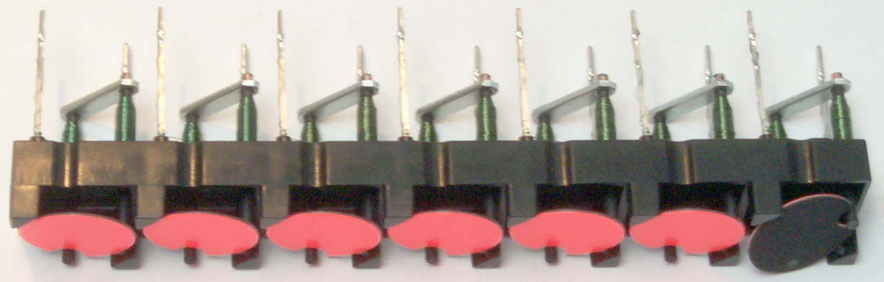
Flipping Dot
Another type of display is the flipping disk dot (
Wiki).
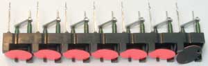
The stick
is about 106 mm long and each disk is about 14 mm in diameter.
Note that a common dot matrix display (
Wiki)
is 5x7 dots and so if you stack 5 of these 7-dot sticks you can
form any character.
This flip dot stick came from
Alpha Zeta in
Poland that has taken over the FP Electric
Flip Dot products including
these
flip
dot
stripes.
These have a magnetic memory and so consume no power once they are
set. In the photo above you can see one of the 7 dots has
been flipped, but stays flipped when power is removed. These
were used on bus destination signs but have been replaced by
LEDs. They also were used at airports for the arrival and
departure display boards which made a distinctive sound when they
were updated. Still are used for highway road condition and
status signs.
I think the factory flip time of 50 ms can be greatly reduced by
using a high voltage drive and a series resistor, similar to the
way teletype and
stock ticker printers
work. A related but different drive method is instead of
driving from a fixed voltage source a capacitor can be used where
it is sized to deliver just enough energy (1/2CV
2) to
make a reliable flip. This would be handy when a low voltage
battery was used to drive the display at high speed.
Hackaday:
3D
Printed Flip Dots - soft iron screws are needed, not
stainless.
Patents
512395 Producing Illuminated Letters,
James H. Rogers, Jan 9, 1894,
345/30 ; 200/46 - covers an
11 segment display using lamps as well as a matrix display. (note
the patent date)
683133
Interchangeable electric display apparatus,
George
Lafayette Mason,
Mason
Monogram, 1901-09-24, - lights in segmented display
1311118
Three-position annunciator, Wesley H. Geiger, 1919-07-22, -
Railroad
2245493
Electric indicating means, Erich Nothe, Siemens, 1941-06-10, -
aircraft cockpit On/Off indicator
2367299
Magnetic signal,
Ernest
S Mclarn,
Frank
A Leibe,
International
Standard Electric, 1945-01-16, - aircraft cockpit On/Off
indicator
2388448
Indicator,
Edward
V Sundt,
Purcell
Joseph,
Littelfuse,
1945-11-06, - aircraft cockpit On/Off indicator
2415452
Electrical indicating device,
John
A Taylor,
Milton
A Knight, 1947-02-11, - aircraft cockpit On/Off indicator
2585974
Electrical indicating device,
John
A Taylor,
Milton
A Knight, 1952-02-19, - aircraft cockpit On/Off indicator
3163949
Digital illuminated display device,
Paul
R Gley,
Dependable
Printed Circuit Corp, 1965-01-05, - 21 segment (almost a dot
matrix).
3303494
Magnetically operated signs,
Taylor
Maurice Kenyon,
Winrow
Donald,
Ferranti
Ltd, 1967-02-07,
340/815.62 ; 335/266; 335/281 - dot
matrix for sign
Calls:
2959219 Control Apparatus, Hajny (Baso Inc), Nov 8 1960, 431/50
; 137/66; 335/266; 335/281; 361/162; 361/210; 431/48; 431/54;
431/80 - bi-stable magnetic fuel shutoff
3042823 High Speed Electronic Memory, Willard (IBM), Jly 3
1962 - matrix of gas discharge elements
3140553
Magnetically Operated Sign, Taylor (Ferranti Ltd), Jly 14 1964 -
an earlier version of the fliping dot - to replace matrix of
light bulb type sign
3540038
Multi-Color Single Axis Magnetically Actuated Display or
Indicating Element, Taylor (FP), Nov 10 1970
3942274
Strip Module for Sign Element, Winrow (FP), Mar 9 1976,
3975728
Electromagnetic displays with resiliently mounted components,
Winrow (FP), Aug 17 1976
4069480
Blanking circuit for electromagnetic display,
Christopher
Gordon Helwig,
Ferranti
Ltd, 1978-01-17, - dot matrix for sign
4156872
Display element write sensor, Helwig (FP), May 29, 1979, -
H-bridge drive of display element and read back
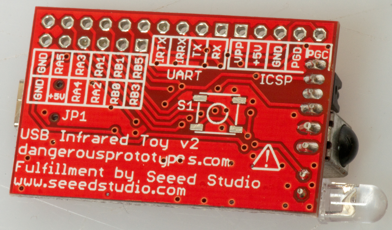
IR USB Toy
It turns out the the IR remote that controls my Blu-ray
player turns on the lights in the ceiling fan when I press
"Return" so I wanted to investigate that and see what would be
needed to use a single "Universal" IR remote instead of the stack
of remotes I no use.
Also the order of turning on the various electronics boxes is
important, for example:
TV/Monitor first, then the audio/video receiver, then the blu-ray
player to make the digital copy stuff happy.
This is a way to read the codes generated by IR transmitters as
typically found in remote controls for electronics, toys, and ceiling fans.
It has the ability to both receive and transmit.
Available from: Dangerous
Prototypes, shipped from Seeed
Studio
Getting it Going
1. Download the firmware package and expand the ZIP file.
2. Plug the unit onto a USB cable and when the New Hardware
window opens and asks for a driver (there is no driver needed)
you need to browse to the location of the firmware package and
inside that the inf-driver folder. Then the OK button will
go from gray to usable, press OK.
3. Open Device Manager (under My Computer / Properties /
Hardware) and the COM port folder. Now unplug the Toy and
notice which COM port turns off, in my case it was COM 18.
4. to check if the Toy is working open Hyperterminal and point
it to your COM port. Take the defaults, and click on the
phone icon to take it off-hook. You should see:
DETECT!DETECT!DETECT!DETECT!DETECT!DETECT!DETECT!DETECT!DETECT!DETECT!DETECT!DET
ECT!DETECT!DETECT!DETECT!DETECT!DETECT!DETECT!DETECT!DETECT!DETECT!DETECT!DETECT
!DETECT!DETECT!DETECT!DETECT!
5. Download and extract the WinLIRC program and run the
.exe. It will fail because there's no .cg (configuration
file), but press continue and then select the USB IR Toy and
your com port, then click CREATE CONFIG. You should get a
DOS window. Follow the instructions using a remote.
6. After following the instructions in the DOS window that
involve pressing buttons on the remote and exiting the program,
open the config.cf file.
The file for the Hiaku Fan follows:
# Please make this file available to others
# by sending it to <lirc@bartelmus.de>
#
# this config file was automatically generated
# using lirc-0.9.0(IRToy) on Sat Aug 03 16:27:02 2013
#
# contributed by
#
#
brand:
..\config.cf
# model no. of remote control:
# devices being controlled by this remote:
#
begin remote
name ..\config.cf
bits
16
flags SPACE_ENC|CONST_LENGTH
eps
30
aeps 100
header 8970
4574
one
491 1733
zero
491 626
ptrail 506
repeat 8972
2311
pre_data_bits 16
pre_data 0xFF
gap
108514
toggle_bit_mask 0x0
begin codes
power
0xC03F
FanUp
0x0AF5
FanDn
0x827D
Whoosh
0x20DF
LightUp
0x42BD
LightDn
0x8A75
Sleep
0xCA35
Timer
0x02FD
Clear
0xF807
LightOnOff
0xC23D
end codes
end remote
XyloBand (Wiki)
The audience for the Biden
announcement the night of 7 Nov 2020 had light sticks that
changed color all at the same time.
One way that might work is based on the Xyloband technology.
YouTube: BigCliveDotCom: Inside
an illuminated (RGB) Xylo Band as used in concerts -
Xyloband
Hacking - hand
held controllers (HTX) -
9318043B2
Systems and methods for coordinating portable display devices, Dennis
Chang, Mobbers
Inc, 2016-04-19, - mentions prior art in the description,
including Xyloband. This patent is about coordinating
mobil phones in a venue like a stadium so that an image can be
generated.
Xyloband
- What's inside one -
The light show that was part of the fireworks was done by
quad-copters flying in formation. It takes a swarm of
hundreds of them to do this with precision station keeping.
Firefly
There are a couple of things involving LEDs with the name
Firefly.
Bio-mimicry device
The idea is to mimic the light flashes of an actual firefly.
6851208
Simulated firefly, Timothy
L. Carter, Spartus
Technology, 2005-02-08, - set of 16
Solar powered LEDs. - D580074
Firefly light emitting diode (LED),
8928227
Light emitting bio-mimicry device, Thomas
John Padula, Autumn
Collett Cardone,
Firefly Wind Direction indicator
sensitive to 1"/second.
8291759
Fluid flow direction detection, Thomas
Center Galley, Arnell
Jean Galley, Harbinder
S. Pordal, James
F. Yoder, Intrinsic
Minds, 2012-10-23, - a resistor at the center is heated and
any wind will blow the plume of war air outward from the
center. There are two rings of eight thermistors that sense
the direction the plume of warm air is moving.
7971478
Wind sensor, Harvey
Harrison, Richard
Paskowsky, Harrison
Eng, 2011-07-05, - Dual (to get polarity of wind) crossed
hot wires gives speed and direction.
Links
Agilent
(HP) - LEDs,
Newark
Electronics for small qty buys -
All Electronics - LEDs
American Bright
Optoelectronics -
American Opto Plus -
B. G. Micro - LEDs
Best Hong Kong - eBay - Nov 2007 135
Cd White, 300 Cd Green 10 mm LEDs
Bivar, Inc. -
Brock's LED
Flashlight Links -
Carclo-Optics - High
Brightness LED optics - (CTP-COIL is US warehouse the products
are magnifying glasses)
Color Kinetics - C
series can lights with 16 million colors and based on many RGB type
white LEDs. US
patent 6016038: Multicolored LED lighting method and apparatus
CMG Equipment - LED
flashlights and one with a PIR switch to come on when movement is
detected
Cree Research (includes Nitres,
Inc.)- silicon carbide (SiC) based products including low current
and high brightness LEDs
Data Display Products -
Dialight Corp - assemblies
for trucks, signals, etc.
Don Klipstein's LED
& Light Bulb Pages - LED Main Page -
Electronic Goldmine -
Everlight Electronics
- LEDs and other electro optical products
Fraen - Optics for High
Brightness LEDs - Future stocks some
Gerrys PIC Based Electronics
Projects - RGB and other LED projects
HB Electronic
Components, Cina - accepts PayPal
HDS Systems -
rugged LED light
Hosfelt Electronics - LEDs
Infineon - lamps
Joule Theif -
origional (as far as I know) version of single cell LED circuit
Kingbright -
lamps
L2Optics -
LCK-LED - high brightness and
others, on line store
LED Corp - White LED in
conventional flashlight bulb base & flashlights
LEDdynamics - LuxDrive -
LED Museum -
small qty sales
-
LED PWM Control
using a PIC
Ledtech Electronics, Inc. -
Ledtronics - lamps
and indicators
Leotech Electronics -
lighting & signs
LighThings - dealer in many
brands of LED products
LSDiodes - good prices on
very high brightness LEDs, individual LEDs, not digits or characters
Lumex - LED, displays, etc.
LumiLeds - traffic lights,
automotive, signs by Philips
LuminArt - a sphere whose
color can be changed by turning a knob and brightness by another
knob. How big, power source?? about $190
Marktech Optoelectronics
- N. America technical sales for Toshiba
-
Mouser - King
Bright Multi-Color Lamp T-1 3/4 LF59EMBGMBW
-
Mule Lighting -
Nicha -
One Stop Displays - OLED
Opto Technology - LED cluster
lamps in heat-sinkable TO-66 packages
Para Light Electronics - lamps
& displays
Philips - LumiLeds - Luxeon
Photon Micro-Light -
keychain LED lights, many models trade color, brightness, battery
life
Polymer Optics -
plastic LED lens
Quantsuff's Circuit Page -
single transistor blocking oscillator & two transistor single
inductor boost circuits, combined FET &
bipolar blocking osc circuit
Radio
Shack - long list of LEDs
Roithner-laser - large
selection of LEDs
covering a wide range of wavelengths
Sloan Company -
The LED Light - lamps,
flashlights, 120 VAC lamps, more
Toshiba. Hit the "Products
List" selector and select optoelectronics. LEC chips
toyoda-gosei - LEC
chips
Back to Brooke's PRC68, Products for Sale, Alphabetical List of Web pages, Flashlights & Patents, Electro-Optical Gadgets, Electronics, Home
pages
page created 16 Sep. 2000.
 The main problem I've found is the high
amount of wasted power. For example the Made in China
"Luxeon K2 Power 120 Lumens" flashlight that runs on two LIR123A
cells. This is a cheap flashlight that uses a 4.2 Ohm
resistor to set the LED current. Since two 3.4 Volt
batteries are being used and the voltage drop on the LED is
about 3.85 volts that leaves 2.95 volts or 700 ma or about 2
Watts to dissipate in the resistor and about 2.7 Watts in the
LED for a total nearing 5 watts. This means that after
about 10 minutes this flashlight it too hot to hold.
Lumens per Watt doesn't mean much when you burn power in a
resistor.
The main problem I've found is the high
amount of wasted power. For example the Made in China
"Luxeon K2 Power 120 Lumens" flashlight that runs on two LIR123A
cells. This is a cheap flashlight that uses a 4.2 Ohm
resistor to set the LED current. Since two 3.4 Volt
batteries are being used and the voltage drop on the LED is
about 3.85 volts that leaves 2.95 volts or 700 ma or about 2
Watts to dissipate in the resistor and about 2.7 Watts in the
LED for a total nearing 5 watts. This means that after
about 10 minutes this flashlight it too hot to hold.
Lumens per Watt doesn't mean much when you burn power in a
resistor.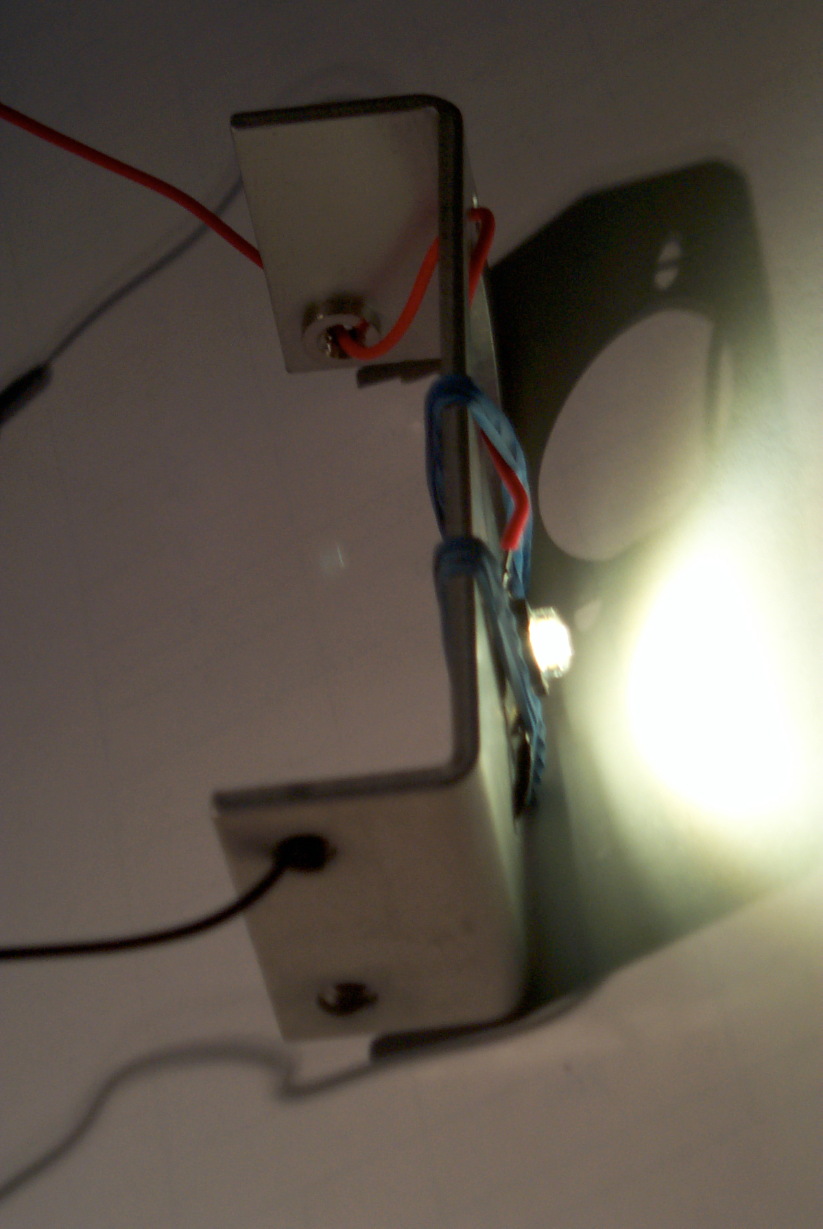


