CP-5131/GYC or PSG-9 Message
Terminal
CHS-2 Handheld Terminal Unit (HTU)
© Brooke Clarke 2008 - 2014
PSG-9
Background
Identification & Markings
Comments
Inside
Power
Litton DC/DCPowerstick
Start Up
CCFL Back Light
Operating System
PCMCIA Hard Drive
PCMCIA to PCI Adapter
Storage Formats
Connectors - WHAT IS J2?
Controls & Indicators
Manuals
Reference
CA-5033/UYC Printer
Vehicle Mount
Related
Links
Figures:
Background
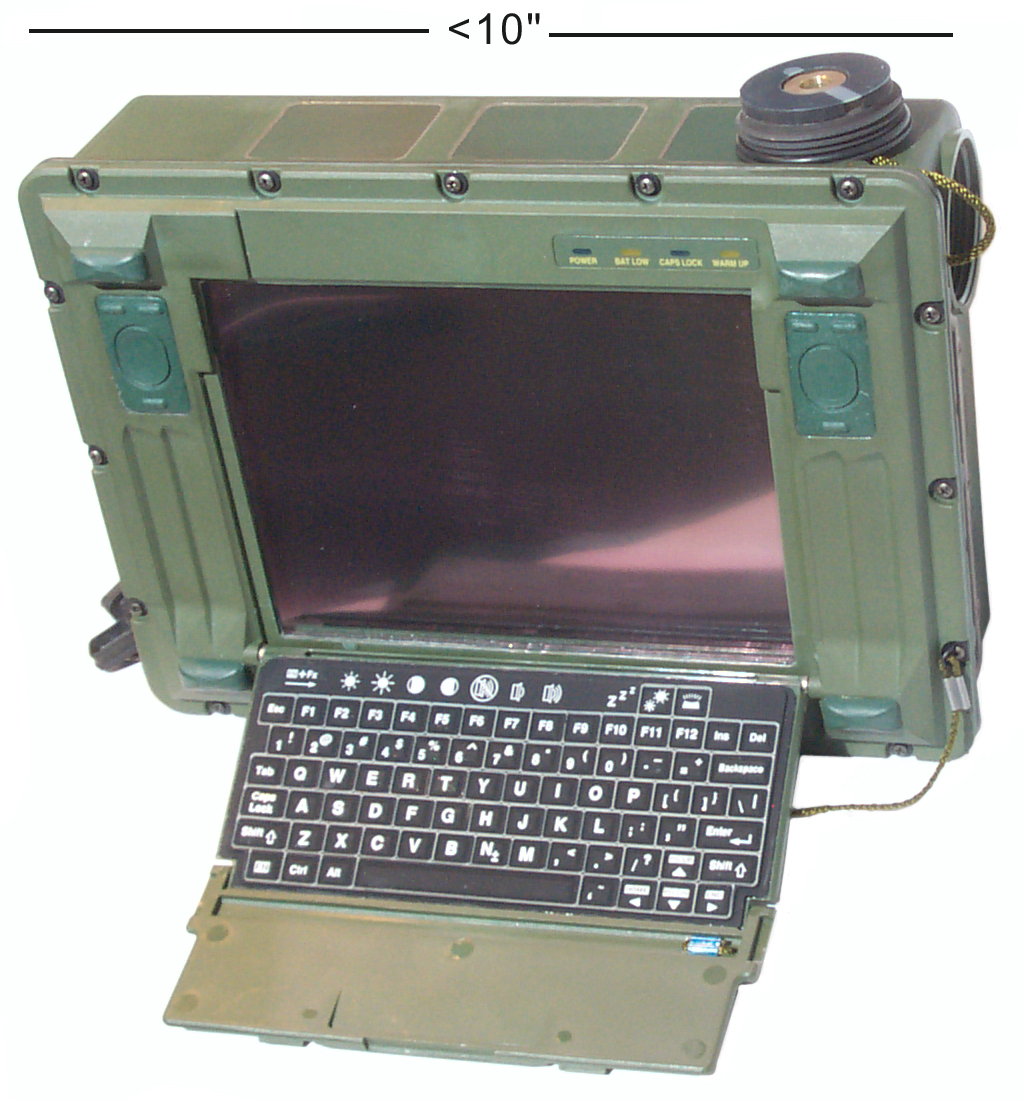
This is a small Handheld Terminal
Unit (HTU). It's part of the military Common Hardware
Software program. The idea being that computers can be
customized by what software they run. This is a 486 class
CPU with 32 MB ram that uses PCMCIA for all the disks thus
allowing for removable disks, probably as a security
measure. The DRS Technoligies
Scorpion
is the 2008 version.
Comparing the PSG-9 and the Scorpion
|
PSG-9
|
Scorpion
|
Size
|
9 x 7 x
3.2
|
9 x 7 x
3.2
|
Wt lbs
|
4.2
|
8.5
|
Disp
pix
|
640x480
|
800x600
|
RAM
|
32 MB
|
2 GB
|
DC Ext
Pwr
|
8 V
|
28 V
|
Batt
|
BA-5600
|
BB-2600
|
These showed up on eBay for under $100. Looking for any info
on it.
Let me know.
There are two PCMCIA slots on the other side, one about 3.5" deep
and the other about 5.5" deep.
Is there a way to load Windows in a PCMCIA card so the computer
will boot from it?
There is a small PCMCIA internal hard drive (not in the externally
accessible slots).
screen size is 6 1/8" wide by 4 1/2" high.
When an external monitor is used there is color info. Don't
yet know about the PSG-9 LCD.
Note the adjustments for LCD brightness and contrast work on the
LCD hardware, not the external monitor.
5 May 2008 - I think the reason these computers were surplused is
because they have an internal BIOS battery. That it's
soldered to the mother board is even worse. And that it's
not available is much worse. The cost to the government to
have a qualified person open the computer and install the BIOS
battery would be staggering. Afte the battery was installed
then the BIOS settings need to be restored. Note when
the BIOS battery goes bad you loose the use of the internal hard
drive.
|
Dead
BIOS Battery
The problem is the BIOS battery died. That
prevents access to the internal hard drive which
contains DOS.
- The battery is no longer available.
- The Cylinders, Heads and Sectors/Track (CHS) is
unknown.
|
12 May 2008 - I've received an email indicating that the
switch shown in
Fig 20 is to zeroize
the BIOS. When I found the switch I cycled it a few times to
be sure the contacts were not oxidized and don't see how it could
change anything since the BIOS battery is dead. But now the
BIOS does not run at power up.
Also that J17, the 4 pin connector you can see inside the external
PCMCIA access hole is for loading the BIOS. If you know more
please
tell me.
BIOS Updating & the Switch & J17
"The switch on most motherboards
"to zeroize the BIOS" is usually there to allow a new BIOS image
to be loaded into the BIOS EPROM. This is usually done off of a
floppy with an appropriate loader utility and the new BIOS image
on the floppy. Typical sequence is to power down, insert and
boot off of the BIOS imaging floppy, run the utility on the
floppy and load the new (presumably updated) BIOS into the
EPROM; then power down, reset the switch jumper/back to normal,
and power up and boot with the new BIOS intact. I would expect
the four pin connector to be some form of serial interface (not
necessarily RS-232 nor RS-449, possibly just TTL levels) used to
load the EPROM on board from some external computer.
I've not seen a true "zeroizing" BIOS switch/jumper, and with
most commercial motherboards, the switch only enables BIOS
loading, it actually doesn't zero out the old BIOS
automatically.
This implies that you would need the utility, the BIOS image,
and the interface spec to successfully update the BIOS."
Hope this is of some help.
Best Regards,
Geoff
Identification & Markings
Markings:
13973 ASSY 420001-105 SERNO 50336
13975 ASSY 420080-103 SERNO 1989
A Canadian eBay auction shows:
01-480-0622
014800622
7010-01-480-0622
7010014800622
The Canadian nomenclature CP-5131/GYC would follow the
NATO naming scheme which would translate:
G
|
General Ground
|
Y
|
Data Processing
|
C
|
Communications
|
The PSG-9 nomenclature would translate as:
P
|
Portable
|
S
|
Special or Combination
|
G
|
Fire Control
|
Comments
Geoffrey Bunza wrote:
Comments on the PSG-9:
The PSG-9 uses a BA-5600 which has an 8.4V has center
contact NEGATIVE outside contacts (half moons) are POSITIVE
& Longer cylinder 3 D LiSO2 cells vs. the BA-5800 which
has 6.0V has center contact POSITIVE and outside circular
contact NEGATIVE
& Shorter cylinder 2 D LiSO2 cells.
>From memory:
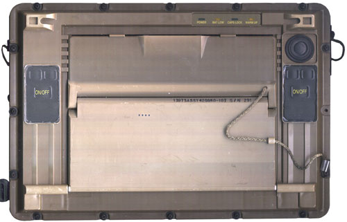
--The unit turns on by pressing both buttons on the front panel in
the upper left and right simultaneously (hold down until turn on).
--If you have a bad screen you can connect a VGA screen to its 15
pin subminiature D connector.
--The small metal circular connectors are "Lemo" connectors
(Brooke comment: I don't think so,
Lemo
connectors use a push on, pull off mechanism, not threads)
--It is essentially a slow PC architecture, the cardbus (PCMCIA)
system is standard, but the boot setup is not, and can be
configured by going into the BIOS setup (usual) (I don't remember
the key sequence to get there)
--As a PC with only PCMCIA card disks (which includes the internal
hard disk, by the way--only accessible by taking the entire thing
apart) you can boot off of an insertable disk by first
reconfiguring the BIOS to select it to boot. The PCMCIA insertable
disk must be loaded elsewhere: find a laptop with a PCMCIA slot,
and a floppy and/or a CD. Get a 1 or more GB PCMCIA drive or
compact flash with PCMCIA adapter, load in your new found laptop,
and put a bootable DOS image of system on the PCMCIA disk; then
copy your OS of choice, that is likely the INSTALLATION CD, onto
the PCMCIA disk. Insert the PCMCIA disk into the PSG-9, boot DOS
or equivalent, and then start your OS installation. This needs to
be done so your OS installer can recognize the internal
configuration of the PSG-9 hardware.
If you can't boot DOS you have other problems-- either hardware or
BIOS settings, or you didn't create a bootable PCMCIA disk.
Hope this helps.
--Geoff
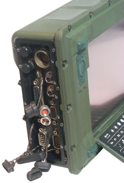
Inside
There may be a way to either find or
add an external power connection to the existing connector
pins. So opening up is the next step.
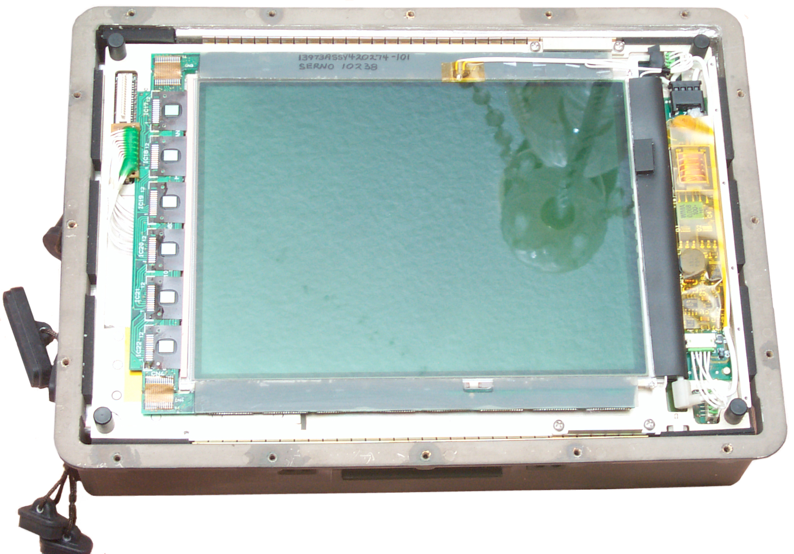
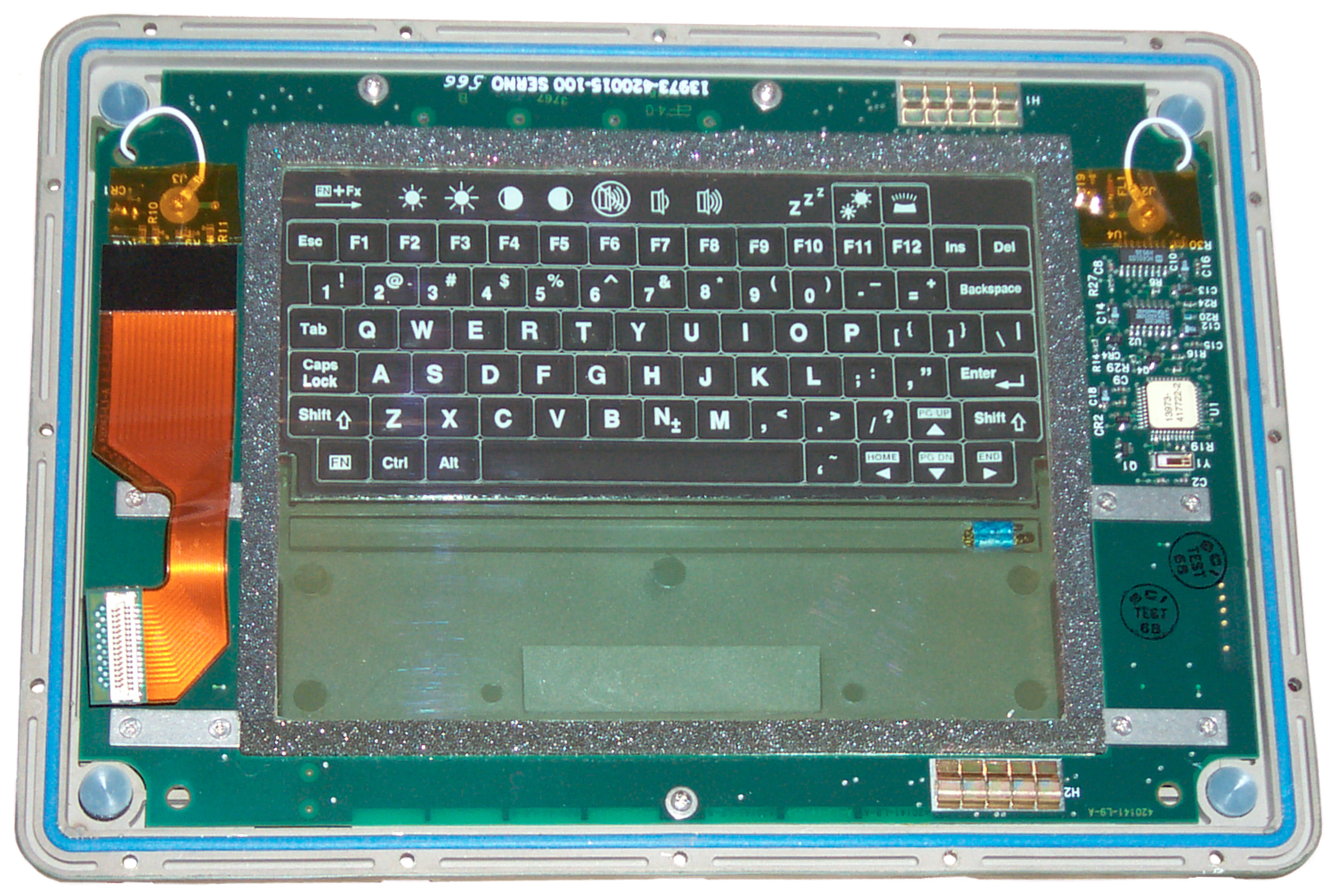
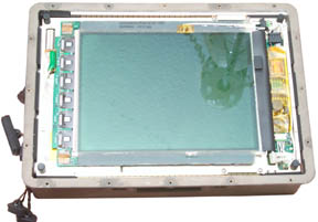
When the lid is removed what's under it is the LCD.
A glass panel comes off with the lid.
To the right of the screen is the inverter transformer
that's part of the CCFL backlighting. |
This is looking up from
inside when the keyboard is folded flat.
|
Fig 7
LCD after top removed
|
Fig 8
bottom of keyboard seen from inside

|
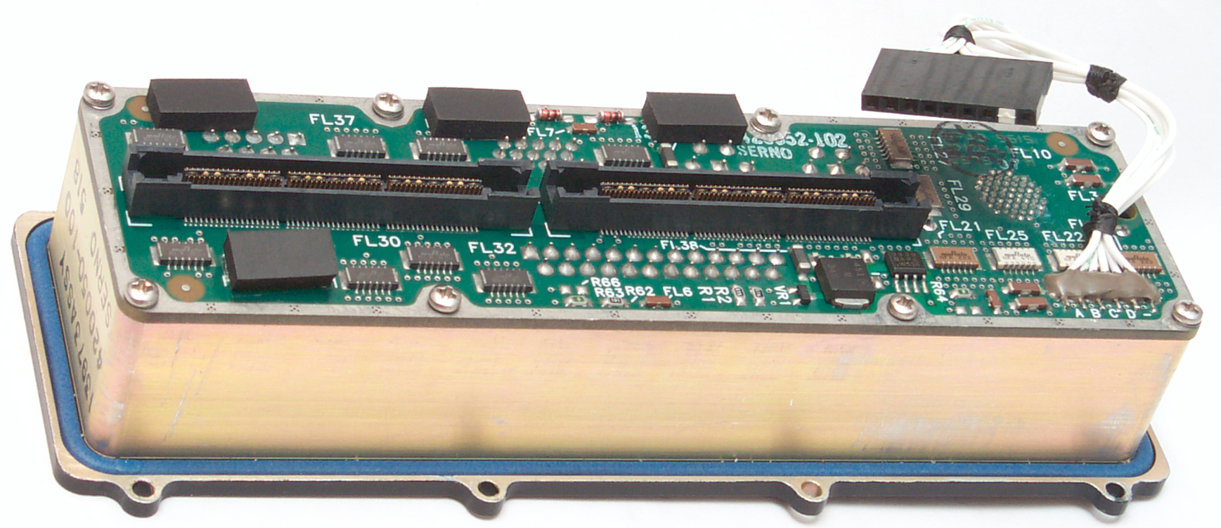
Fig 9
Back of connector sub assembly
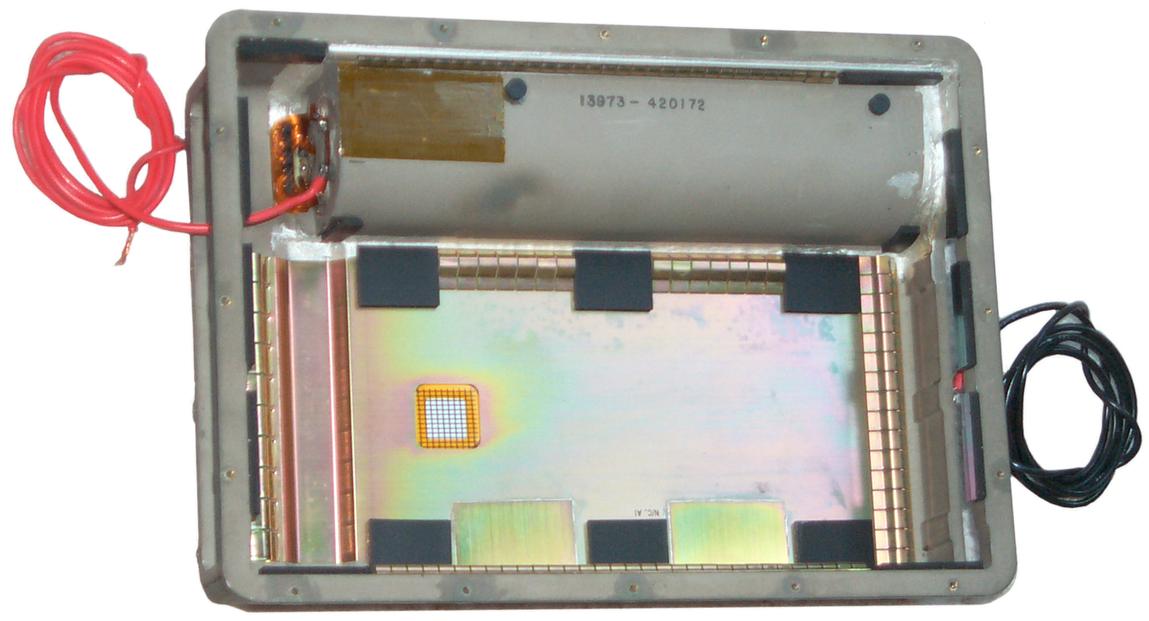
|
Fig
10 Cavity in main box behind connector sub assembly
|
I didn't notice any alien beings when taking these photo,
but Fig 7 seems to show the reflection of one looking over my
shoulder? Fig 10 is the most interesting since there's
access to the bottom of the battery compartment. More later
after the Fluke 87 does it's thing.
To remove the motherboard assembly after the top and connector
assemblies have been removed, just lift it out.
It is possible to removve the motherboard addembly with the
connector assembly installed, the ribbon cables that connect to
the connectors are long enough.
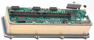
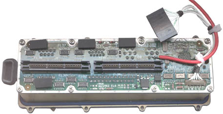
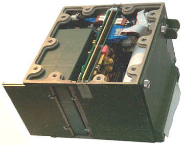
Fig 15 Empty Box

|
Fig 16 Motherboard Assy
|
Red wire soldered to one of
the 4 positive battery terminals.
Black wire has a crimped
ring tongue terminal with a 2-56 screw holding it.
|
The BIOS setting back up
battery measures 0 volts. The ICs have 1994 and 1995
date codes
so it's (2008 - 1995) about 13 years old. It's an
ER10/28 3.6 Volt 1/2 length AAA. I doubt a AA
diameter will fit this corner that's beside the main
battery compartment.
The smaller board with one of the flex circuits connected
is the power supply.
There's another same size board under it.
Note the black feet on the back side to protect the face
of the LCD screen when it's set down.
The small white connector on the main board near the upper
left corner is probably the audio
like would be connected to a CD player.
|
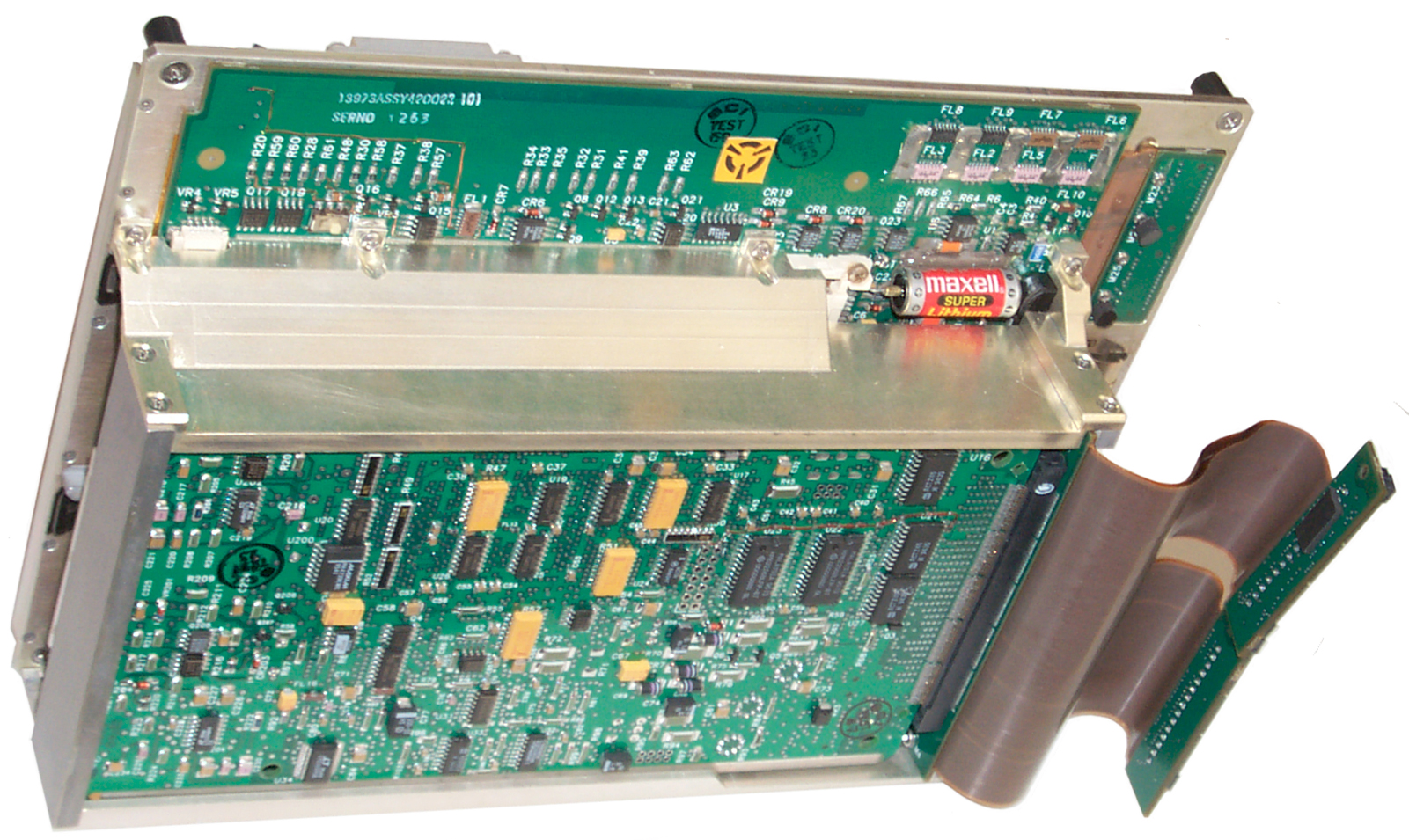
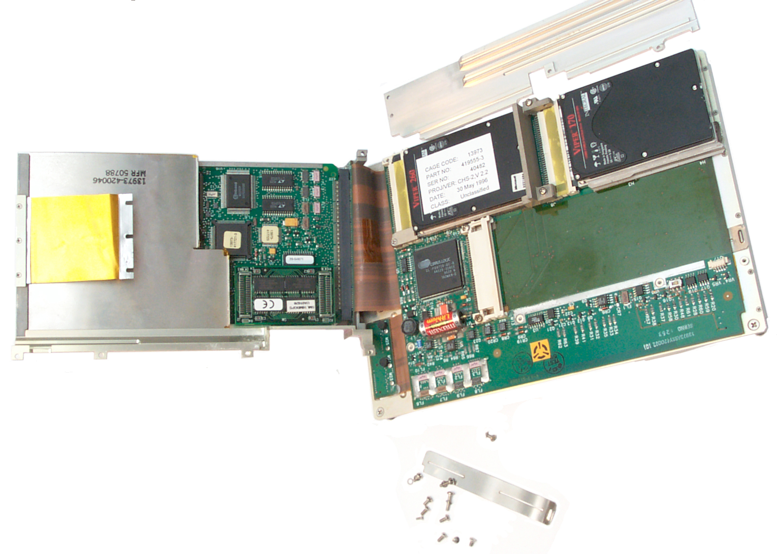
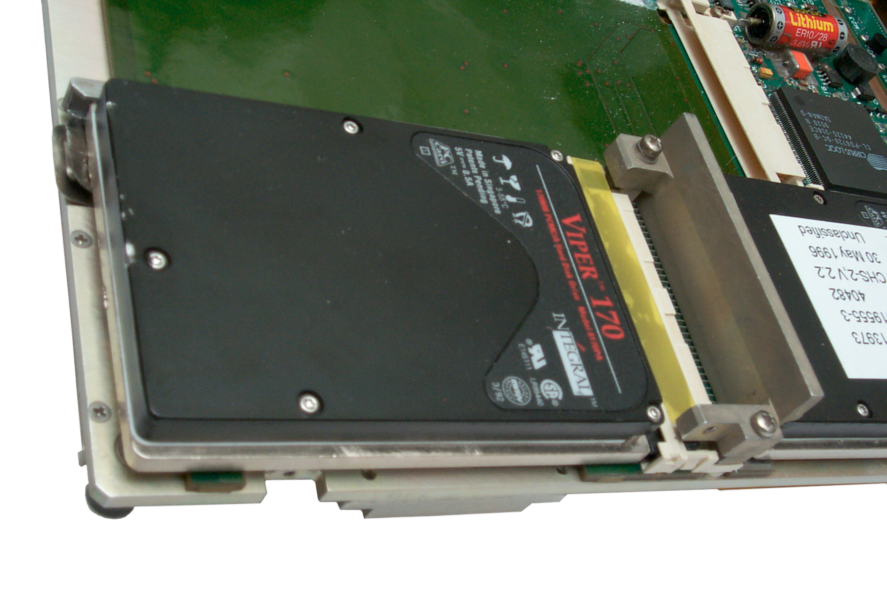
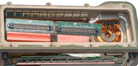
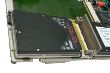
Fig 18 Card Cage Folded open exposing
internal Hard Drive
The Viper drive on the right I've added.
The stock hard drive has the white label.
CPU board on left of fled cables.

|
Fig 19 Back Up battery 1/2 AAA

|
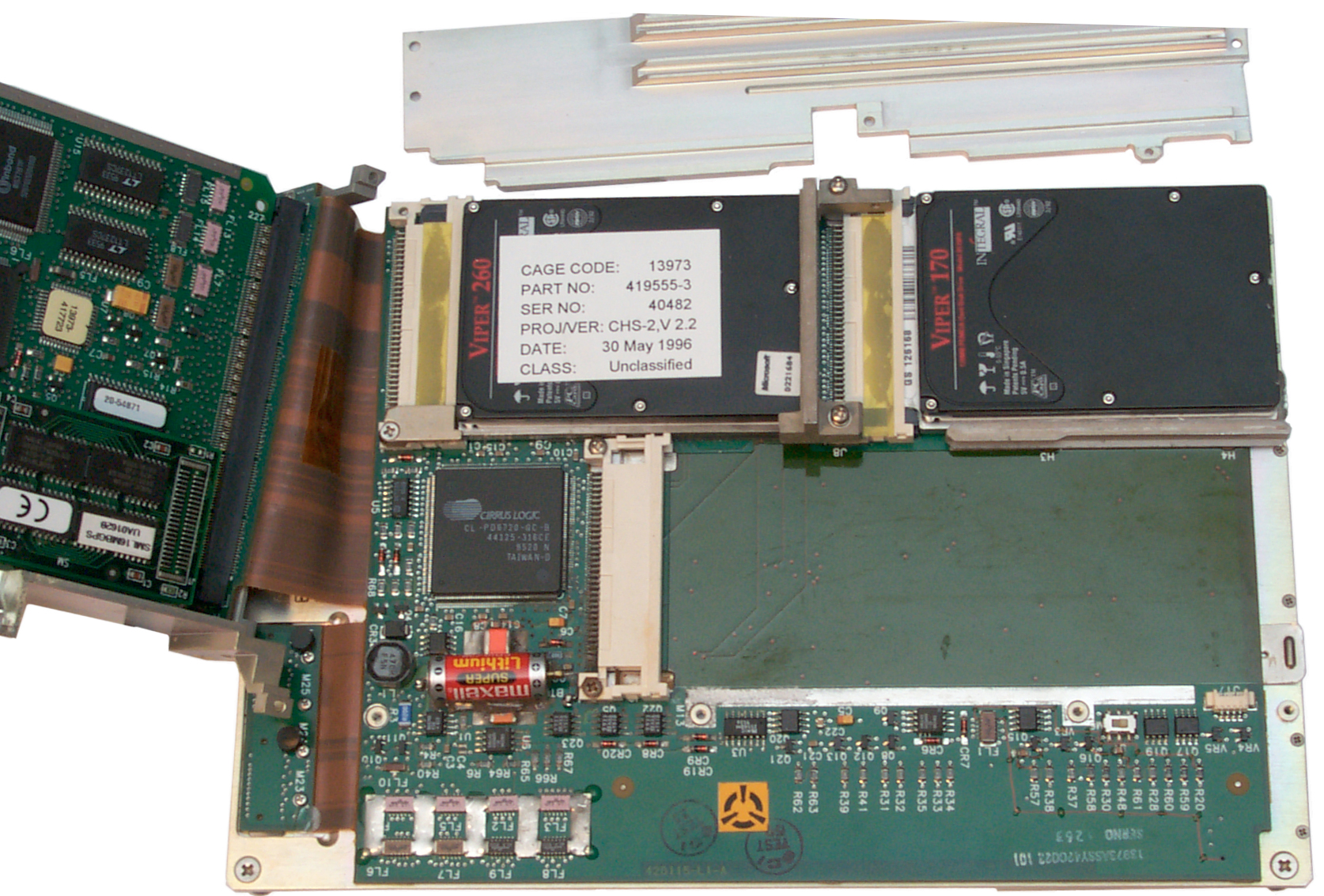
Card Cage Folded to Reveal
CPU board w/ sheetmetal cover in place & Mother Board
Internal hard drive is PCMCIA Viper 260 MB marked
"unclassified on white sticker
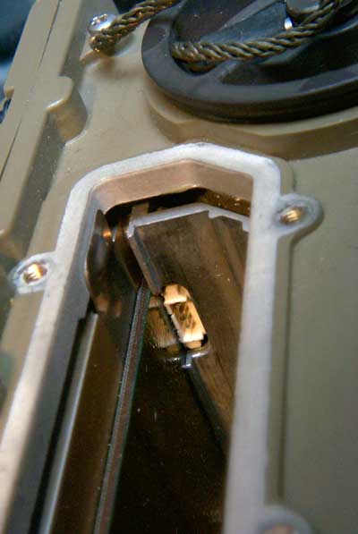
|
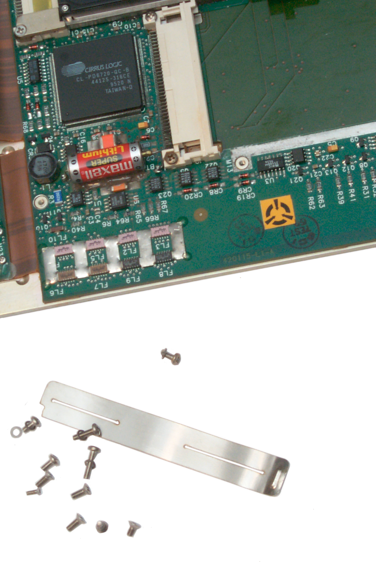
CPU, dead BIOS battery and
just out of photo at right front mystry switch.
|
Fig 20
Closer View of Internal Hard Drive (left with white paper
label)
and added Viper Drive (or right)

|
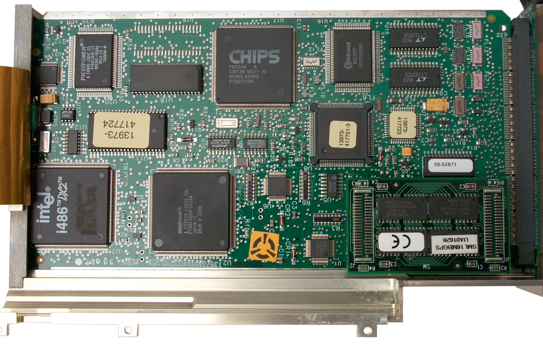
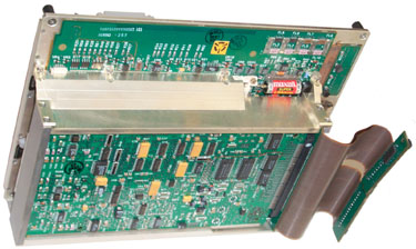
Fig 21
CPU Board

|
Mother
board
^
switch
Do Not Operate
Switch, Do Not Seperate Cards From Flex Connector.
Doing either of the
above may disable BIOS.
|
PSG-9 CPU Board w/o
sheetmetal cover
|
Fig 20A PSG-9 BIOS load 4 pin
connector
|
|
This may be the connector
needed to load the BIOS. It's very close to the
switch shown in Fig 20 and the backup battery.
|
|
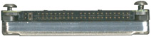
Fig 22
Short External PCMCIA Socket
|
|
Drive Locked into External
PCMCIA Slot No. ?
The metal tab should release the drive, but it's broken
and the drive can not be removed.
|
|
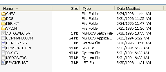
Fig 23 Internal Viper 260 MB Hard Drive
Directory
|
Power
The battery is the BA-5600/U which
is a negative center contact stick with three LiSO
2
cells or about 9 volts.
Saft
data sheet for BA-5600/U, shows it's for the AN/PSC-2.
In addition to the dumb BA-5600 there are apparently some smart
battery options for this computer.
BB-741/GYC, BT70341, (it's not clear what these numbers are:
420324-100, 842558-1).
In addition to the center negative contact and two half moon
positive contacts there are four additional contacts:
A = CHRGPATH
B = MOD
C = +12
D = BATINFO
The BB-2600 (NSN 6140-01-467-5853, BT-70443) is a Li-Ion
rechargeable.
It has been replaced by the BB-2600A/U (NSN 6140-01-490-4311,
BT-70743)
It does not have the ABCD smart battery contacts. The gas
gauge
and charging contacts are on the cap end with the regular
discharge
contacts on the other end.
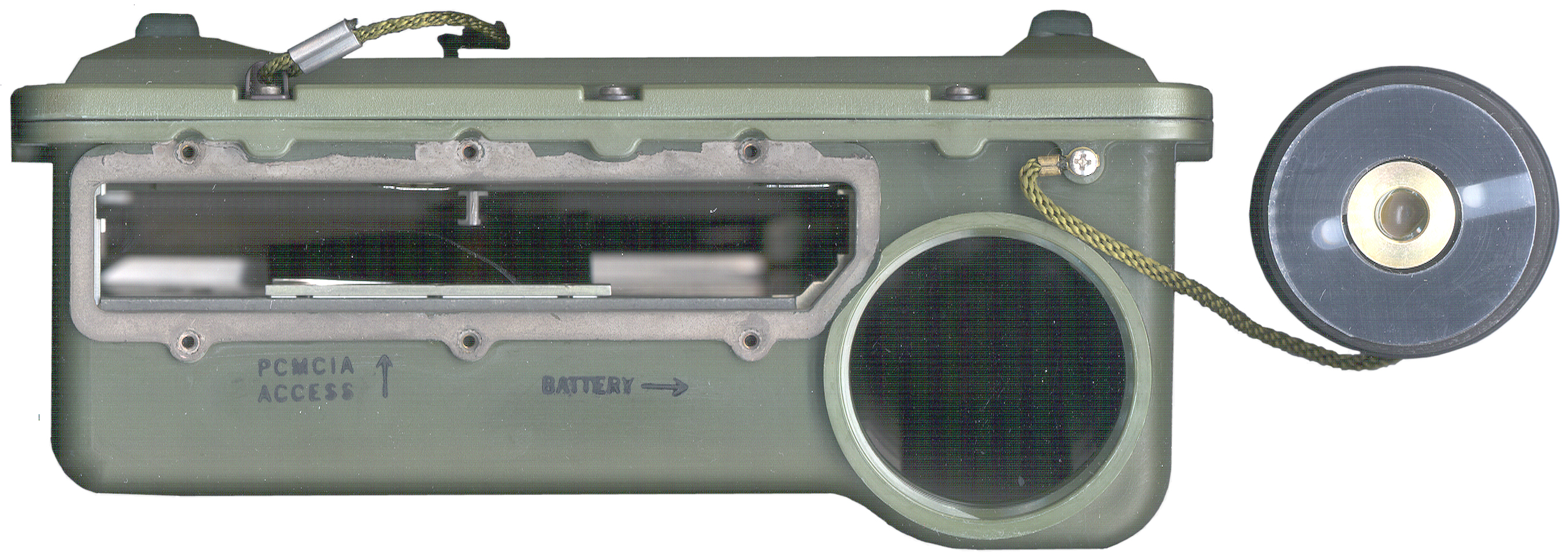
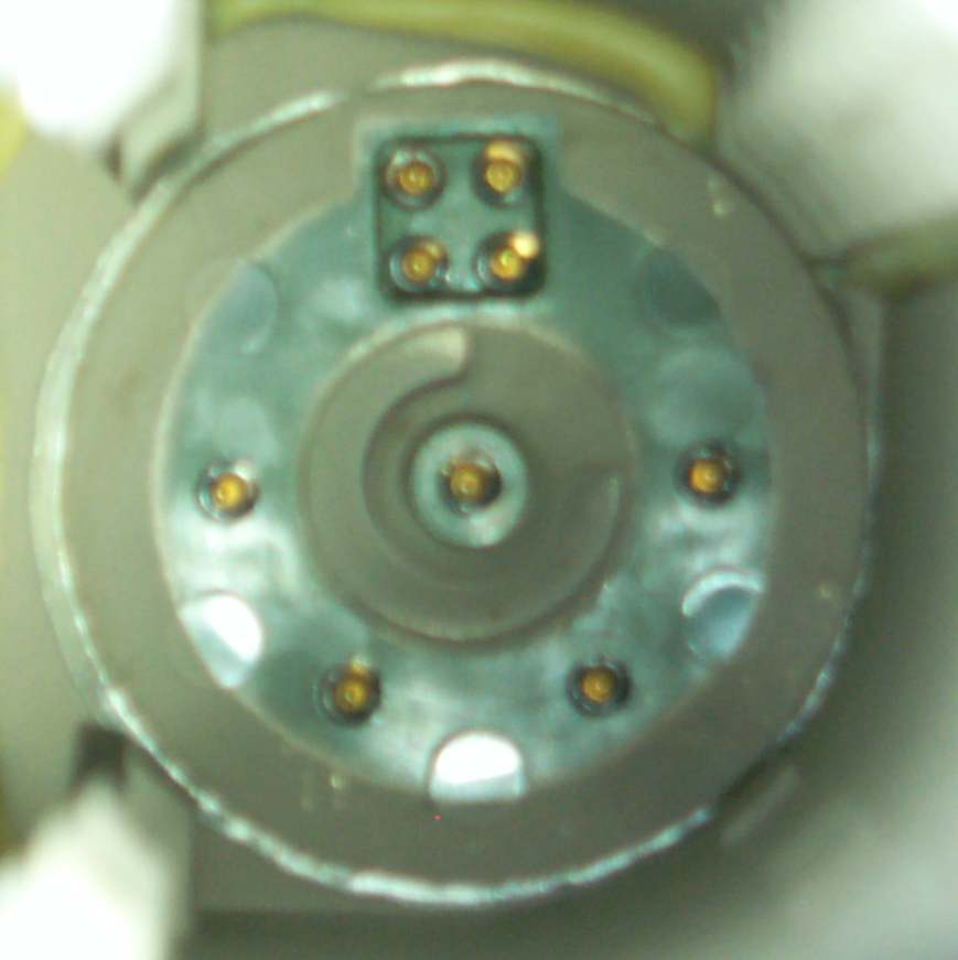
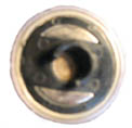
Fig 11 Battery Socket
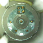
Looking
into the battery compartment.
The center contact is negative and is connected to the chassis,
i.e. is
ground and shows up on the metal case and a lot of places on the
connectors.
One or more of the 4 contacts at the bottom will contact the half
moon
positive terminals no matter at what rotation a dumb battery is
installed.
The four contacts at the top in a square pattern are recessed
below the
face and so will not be touched by a dumb battery. When a smart
battery
is installed it needs to be rotated so the projection matches the
pocket.
Just to the left of this photo is the wall that's shown
above
in Fig 2 on the top. The three dark green square shapes are
thin
panels that will rupture if the battery vents or explodes.
Just
inside each of them the metal frame has eight holes that hopefully
will
allow gas to pass but stop large chunks from flying out.
There
are some dead lined BA-5600 batteries that have exploded and for
them
the self discharge switch should not be pressed.
This is the same system used on laptop computers where the gas
gauge
has a serial port to report the batteries state of charge.
So I suspect the cells are Li-Ion. If the battery can be
charged
while in the PSG-9 then there must be an external power input
connector, WHERE IS THE EXTERNAL POWER INPUT?
let
me know
This may be the first military battery to have a smart gas
gauge.
Many of them have LCD bar graph indicator gas gauges.
The
M455-1/GRC-206 Power Source has an
8
Volt output for powering either this device or similar 8 volt
computer
type equipment.
Backup Battery
There is a 3.6 Volt 1/2 size AAA (9.7 mm dia x 25 mm
long)
lithium backup battery with leads soldered to the
motherboard.
See
Fig 16.
This one is completely dead. It's required if you want the
BIOS
settings to be remembered. And that's required to set the
hard
drive Cylinders, Heads and Sectors.
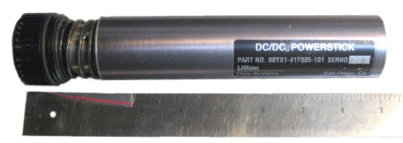
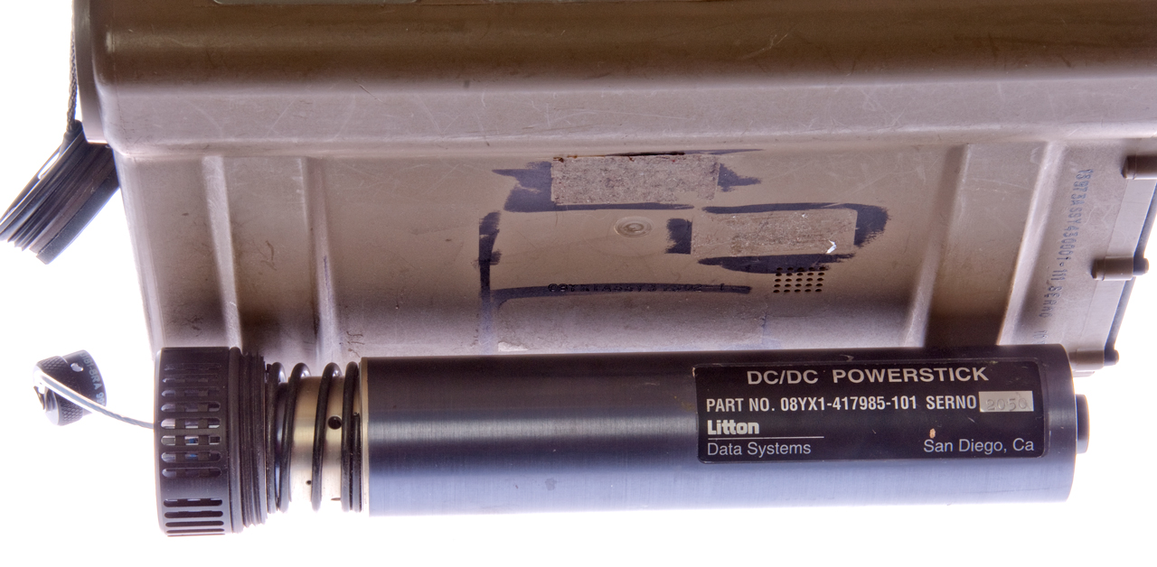
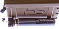
Litton Data Systems DC/DC Powerstick p/n:
08YX1-417985-101
Fig 12 Powerstick Connector & Heat
Sink

|
Fig 13 Powerstick side veiw

|
Fig 14 Powerstick plug end
|
External
end
with connector for military
vehicle power (20 to 30 VDC) which when
dropped down to 8 will dissipate a lot
of power if done with a linear regulator.
This looks like a linear regulator with all
the heat sinking and metal construction.
|
The cap
at
the left screws into the PSG-9 so the normal
battery cover is left hanging on it's lanyard.
|
This
end
looks like the battery
It does not contain the smart
contacts so it's dumb.
|
photos
courtesy
of Kurt Lesser
Kurt called this a vehicle battery adapter but I would
call it a
vehicle power adapter meaning there's no battery involved.
Mike Murphy
sells the power stick.
I found the one below on eBay for a very reasonable price.
|
Installed in PSG-9
connextor is marked : MS3470W8-33P Aero 9930-1
positions for 3 male pins but only A & B installed.
|
Next to PSG-9
|
|
J2 External Power Connector
Although J2 is in the same connector
family as J3 they are keyed differently so you can not plug the
external power cable (J2) into the keyboard/mouse jack (J3).
See Connectors below for photo of
J2.
Start Up
8 March 2008 - With 9 volts applied
to
the battery terminals (soldered red wire to one of the four
battery
socket pins after removing the connector sub assembly, Fig
10).
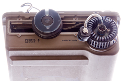
To the upper right and left of the LCD are a couple of momentary
rocker
switches (
Fig 2)that have two bars at the top
and
one bar at the
bottom. When both of the bottom bars are pressed and
held
the computer boots up:
The green POWER LED turns on and the other LEDs do a dance. The
LCD is
showing a PhoenixBIOS DOS boot release 1.13. At first I
thought
the LCD was dead, but when looking at a steep angle from below you
can
see the text. Optimum viewing angle is 45 degrees below
square
on. But it needs a contrast adjustment.
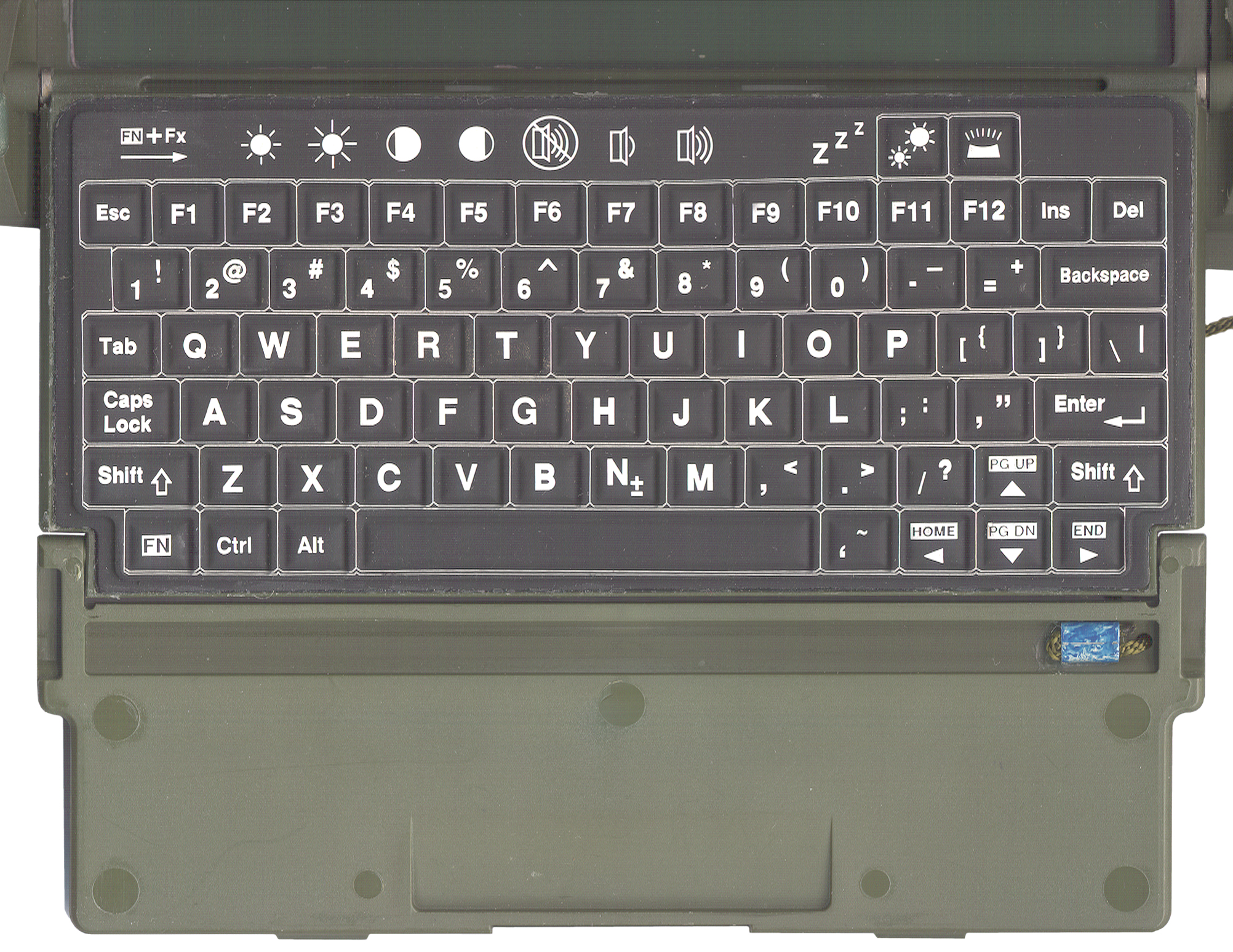
Should the Fn+F4 and Fn+F5 controls work in the PhoenixBIOS
or is
this part of some higher level language (
Fig 4
Keyboard)?
Note: on the keyboard there is a white box surrounding each
key. Those icons without a box are just labels above the
function
keys. The upper right key toggles the keyboard illumination
on
and off. But to see the screen the desk lamp is supplying
the
light.
Maybe the CCFL lamp is bad????
PhoenixBIOS(tm)A486 Version 1.13
Copyright (C) 1985-1992 Phoenix Technologies, Ltd.
All Rights Reserved
Release 1.13
486 DX2
37C51 Revision: V1.2
XICOR Revision: 1.13
Initializing PCMCIA Disk Interface
Initializing IDE Disk Interface
Fixed Disk 1 Failure
Performing Cache Test & Configuration
Cache 1 Enabled
Invalid configuration information - please run SETUP program
Press the F1 key to continue, F2 to run the setup utility
F1:
FDI Modem Presence Check:
Passed
Missing operating system
<CTRL><ALT><DEL>
screen above
F2:
Phoenix SETUP Utility (Version 1.00)
(c) Phoenix Technology Ltd. 1985, 1992 All Rights Reserved
page 1 of 2
** Standard System Parameters **
The time and date can be
set.
<shift><+> works, <-> works..
Diskette A: Not Installed Cyl
Hd
Pre LZ Sec Size
Boot Disk 0: Type 3
615 6 300
615 17 30
Disk
1
Type 1 306
4 120 395
17 10
Internal Disk: Boot Disk 0
Base Memory: 640 KB
PCMCIA Slot:
Slot 2
Extended Memory 31744KB PCMCIA
HDD
Type: Ministor
Speaker Control: Off
Numlock on at boot: NO
Cache:
Enabled
Quick Boot: Off
Default Contrast: 11
External
Monitor: On
Range is 0 to 31
10 or 11 is about the best, but it's not very good,
Page 2 of 2
Power Management: AC Disabled
System Idle After: 3 Seconds
System Idle Speed: Divide by 8
System Standby After: 6 Minutes System
Standby
Speed: Stopped
System Suspend After: 10 Minutes Hard Disk
Off
After: 5 Minutes
<F2 SysInfo>
page 1 if 2
Processor Type: 80486 SX
Coprocessor Type: 80387 or compatible
Option ROMs Found:
Reserved Memory: Not Installed
No Option Roms
found
BIOS Version: 1.13
Video Mode:
03h
Serial Ports:
03F8h 02F8h
Printer Ports:
0378h
? page 2?
Questions:
1) what does video mode 03h mean?
2) what operating systems can be run on a 80486 SX with 32
megabytes of
memory?
3) is there any mouse or touch screen support?
4) is this a special BIOS that has built-in PCMCIA support?
My
WIN XP BIOS does not.
CCFL Back Light
After the boot process the screed went dark. I thought the
CCFL
power supply was defective,hence this paragraph.
10 Mar 2008 - This is normal operation. When using J2 to
provide
external DC power the screen looks normal during the BIOS
part of the boot, then switches to the poor contrast mode.
That
may be because of the contents of the existing hard drive.
For
example the hard drive software may configure the screen
improperly.
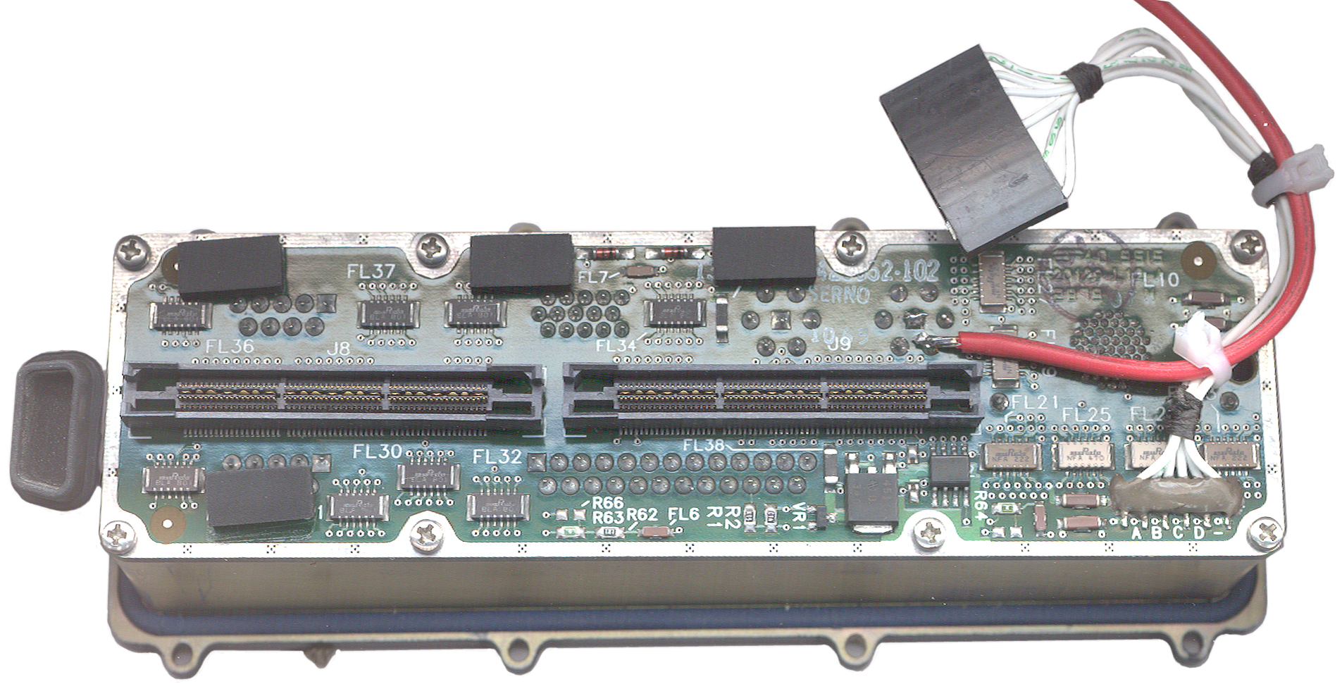
Fig 17 CCFL circuit
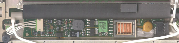
Just to the left of the white 5 terminal input connector the board
is
marked:
420067
L1-A
At the green plug into the white connector at the left I'm calling
the
top pin #1
Pin
|
Ohms
to Gnd
|
Volts
|
1
|
1.3 M
|
8
|
2
|
0
|
0
|
3
|
14.5 k
|
0
|
4
|
3.5 k
|
0
|
5
|
1.6 M
|
0
|
The lamp is 3 mm dia x 128 mm long.
The design is based on
Linear
Technologies LT1172 100kHz, 5A, 2.5A and 1.25A High
Efficiency
Switching Regulators and very close to App Note 49 Fig 2
&
D-1.
The
full primary of the transformer has a data sheet resistance of
0.19
Ohms (center tap half that) and the feedback windings are 0.084
Ohms
each so it's difficult to make resistance measurements.
Instead
of the half bridge transistors specified in the app note some
Zetex parts were used. The Zetex parts are specified to have
ten
times lower Vces.
2783384
ELECTRICAL
INVERTER
CIRCUITS, R.L. Bright & G.H. Royer, Feb 26 1957,
331/113A
; 290/4R; 307/401; 331/181; 363/133 - magnetic saturation of the
transformer is a key parameter.
The LT1172 (U1) has it's Vin pin wired to connector J1 pin 3 and
not to
the +8 volt supply, maybe as a way to disable the LCD?
To check the inverter the switching output pin of U1 or the
emitter of either Q1 or Q2 can be grounded. This turns on
the
CCFL even when the lid is has been removed. When
testing
after starting the computer the lid can be disconnected and the
computer continues to run.
I've tried pulling J1 pins 3, 4 & 5 up and down one at a time
(I
don't have enough hands to do more, and no single pin will turn on
the
CCFL. Note the Royer patent shows that a couple of
transistors, a
special transformer and a source of DC are all that's needed to
make an
inverter. The 1172 is there to regulate the current and
control
the brightness, i.e. lamp current.
Operating System
The short bars above the starting
longer bars are the navigation buttons. The screen is VGA
color,
so some flavor of Windows should run.
Also in a military environment a mouse does not make sense.
Win
XP requires a minimum of 256 MB of RAM and so is way too
big.
WIN 3.1 would fit and WIN 95 or WIN 98 might fit.
DOS 6.n makes the most sense.
14 March 2008 - waiting for PCMCIA hard drive.
4 April 2008 - the PCMCIA hard drives have been here for some
time. But when I tried to put them into my laptop - no go.
The hard drives are Type III, i.e. 10 mm high and would not
fit.
So eBay had a PCMCIA to PCI adapter advertised with the words
"works
with Type I, II or III cards and the photo showed a tall slot, BUT
when
it came the slot was about 6 mm nowhere near 10 mm. Well
after
returning it today received an email refunding my purchase.
I
have a feeling that most of these adapters advertised as Type I,
II,
III are only good for the 5 mm cards unless there are explicit
words
stating otherwise.
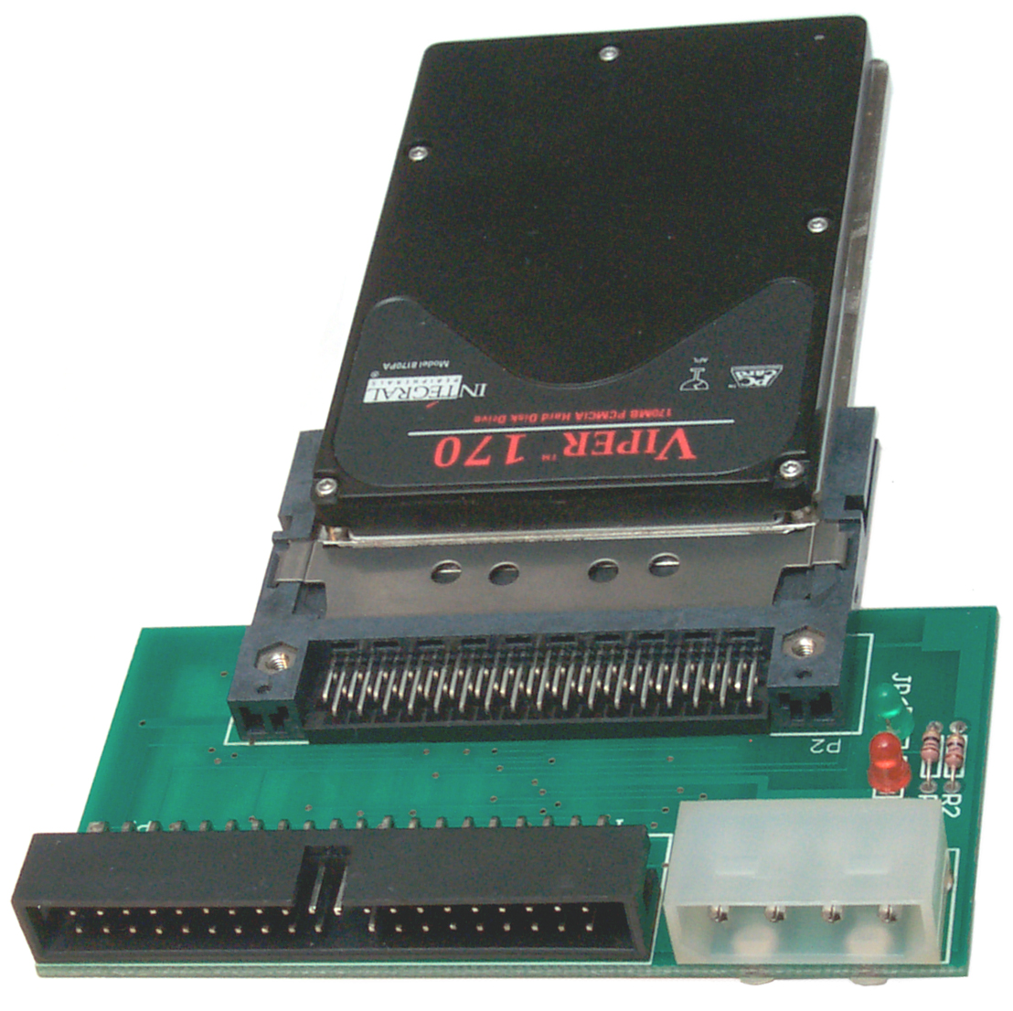
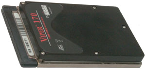
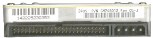
PCMCIA Hard Drive
Fig 24
Viper
170 MB Drive
|
Found on eBay and think it's
the
same type, only half the capacity, as the drives that were
used in the
PSG-9.
This is a 170 MB dirve and they were 340 MB.
This probably is a 16 bit drive, not a 32 bit.
It's twice the height of most PCMCIA cards, Type III, not
Type I or II. |
BIOS Parameters for Viper Drives
Drive
|
Cylinders
|
Heads
|
Sectors/Track
|
Master
|
Slave
|
PreComp
|
Landing
Zone
|
Integral
Viper 85 MB
|
652
|
8
|
32
|
pins 3-4
off
|
pins 3-4
on
|
?
|
? |
| Integral
Viper 170 MB |
981
|
10
|
34
|
pins 3-4
off |
pins 3-4
on |
? |
? |
| Integral
Viper 260 MB |
? |
? |
? |
pins 3-4
off |
pins 3-4
on |
? |
? |
| Integral
Viper 340 MB |
771
|
16
|
54
|
pins 3-4
off |
pins 3-4
on |
? |
? |
The manufacturer was Integral Peripherals. Founded 1990 - last
patent 1997.
James H Morehouse Patents at:
Storage Technology Corporation 1978, 1980
Amcodyne Inc 1982
Prairietek Corp 1988, 1989
Conner Peripherals 1990, 1993, 1995
Integral Peripherals 1990, 1991, 1993, 1994, 1996
Mobile Storage Tech 1994, 1996, 1997, 1998
Seagate Tech 1995
David M. Furay Patents at:
Prairietek Corp 1988, 1989
Conner Peripherals 1990, 1995
Integral Peripherals 1990, 1991, 1993, 1994, 1995, 1996
Mobile Storage Tech 1993, 1996, 1997, 2000
Patents:
5149048 Shock
absorbent
mounting arrangement for disk drive or other component
5161770 Shock
absorbent
mounting arrangement for disk drive or other component
5189576 Rotary
inertial
latch for disk drive actuator
5218253 Spin
motor
for a hard disk assembly
5237472 Rigid
disk
drive with dynamic head loading apparatus
5258695 Spin
motor
control system for a hard disk assembly
5289325 Rigid
disk
drive with dynamic head loading apparatus
5291110 Low
acoustic
noise seeking method and apparatus
5296986 Rotary
intertial
latch for disk drive actuator to protect against rotational
...
5321560 Embedded
servo
system for low power disk drives
5349350 Run
length
limited encoding/decoding system for low power disk drives
5377065 Miniature
hard
disk drive for portable computer having a rotary inertial ...
5379171 Microminiature
hard
disk drive, James H. Morehouse,
David M. Furay, Robert A. Alt, Bruce D. Emo, James A. Dunckley, Jan
3,
1995, 360/105; 360/970.1
looks like Viper mechanism with
alternate interface packaging
5384677 Architecture
for
low-profile disk drive device
5404257 Rotary
inertial
latch for disk drive actuator
5408367 Method
of
optimizing operation of disk drive
5408374 Miniature
hard
disk drive with spin motor for portable computer
5426562 Disk
drive
enclosed by shock absorbent jacket and mounted in electronic ...
5442266 Miniature
disk
drive with spin motor control system
5422770 Shock
bumper
for a head/disk suspension
5448433 Disk
drive
information storage device with baseplate and cover having ...
5457365 Disk
drive
power management system
5465034 Low
acoustic
noise seeking method and apparatus
5466997 Spin
motor
control system for a hard disk assembly
5469314 Miniature
disk
drive with dynamic head loading
5486964 Miniature
disk
drive with dynamic head loading with skewed lifting tab
5526202 Disk
drive
embedded servo system having a servo field with an asymmetrical
...
5539714 Adaptive
runout
compensation for miniature disk drives
5559648 Method
for
optimizing track location during servo writing
5579189 Microminiature
hard
disk drive
5583842 Method
for
improving servo field yields
5592349 Microminiature
disk
drive with clamp having fingers for radially positioning ...
5596458 Variable
zone
layout for information storage disk drive
5689386 Miniature
hard
disk drive with EMI protection and single permanent magnet ...
5694267 Removable
disk
drive and protective device
5724209 Low-profile
disk
mounting assembly, and low-profile disk drives constructed ...
5738533 Electrical
connector
fastened to a rigid member for improved connector ...
5760983 Method
for
optimizing AGC in a servo field including multiple use of an AGC
...
5760986 Microminiature
hard
disk drive
5768049 Disk
drive
apparatus
5790345 Disk
clamp
with tabs shaped to apply equal forces at equally spaced ...
5822150 Disk
drive
including a substantially monolithic stator assembly fabricated
...
5835303 Microminiature
hard
disk drive
5870237 Method
for
variable zone layout for information storage disk drive
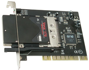
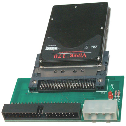
PCMCIA to PCI adapter card to preload
hard
drive
Fig 25
Viper
Drive in PCI slot adapter.
|
This adapter has the proper
large opening so that the 10 mm high hard drive PCMCIA card
can fit
throught the mounting bracket.
Next w'll see if the adapter works and if the drive works.
It did NOT work. I haven't been able to format the
Viper as a
bootable drive. You can read it, format it, write and
read files,
but NOT make it boot DOS. |
14 Apr 2008 - spent most of yesterday trying to make the drive
bootable. It's relativity easy to make a bootable floppy or
CD-ROM with DOS 6.22 but not a hard drive.
The WIN XP computer hard drive is NTFS formatted so can not be read
by
DOS. A fix is probably to get a new drive and format it as FAT
and install WIN 98 (which runs over DOS).
The software packages that make a media bootable are very specific
about working on a floppy or CD and exclude a hard drive for the
options list.
After booting a floppy and running DOS 6.22 the PCMCIA card is NOT a
valid drive. Either /or/ both the BIOS and OS need PCMCIA
drivers
added.
The big chip on the adapter card has "1410" in what's probably the
part
number. TI made a 1410 and 1420 IC for PCMCIA applications so
this is probably a clone of that.
So drivers for the TI 1410 may work. Tried drivers that
displayed
as DOS booted:
"Shining PMIDE-ASC, M17 Carad Services Client V 5.81
No Card Sercices Found!
Configuring the Socket Now!
No PCMCIA Controler Found!
-------------------
------------------
ATA/IDE Fixed & Removable Disk Driver V 5.60
c Shining Tech
--------------------
-------------------
Stablizing Drive . . .
>>> No EIDE Host Adapter Found
>>>IDE Disk Driver is not installed<<<
Press and key to continue
-------------------------
Device driver not found: 'BANANA'.
No valid CDROM device drivers selected
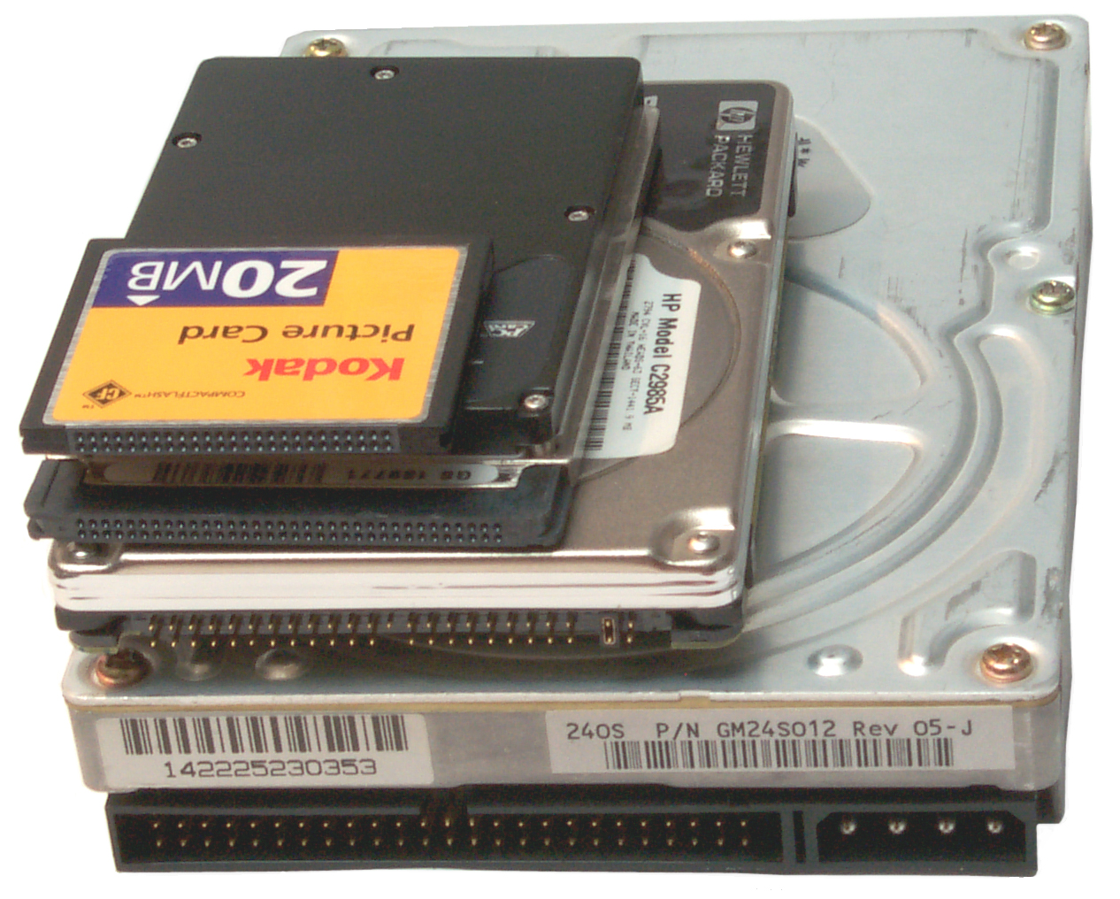
Storage Formats
The signals used for an IDE Hard Drives and for PCMCIA (PC Card) and
for Compact Flash are all the same. That makes is easy to
adapt
from one to the other.
18 April 2008 - have adapter on order that holds PCMCIA drive and
has
IDE connector.
This should allow a very simple format and make system disk on the
PCMCIA drive.
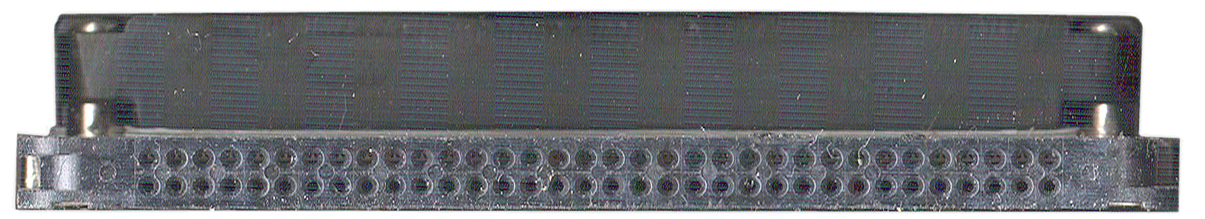
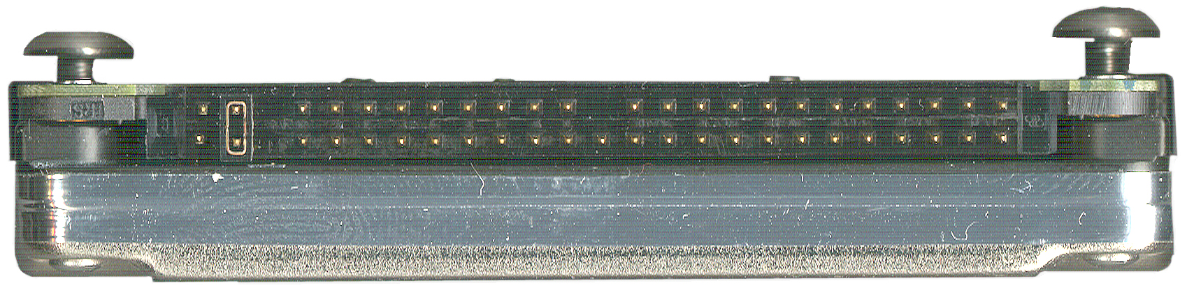
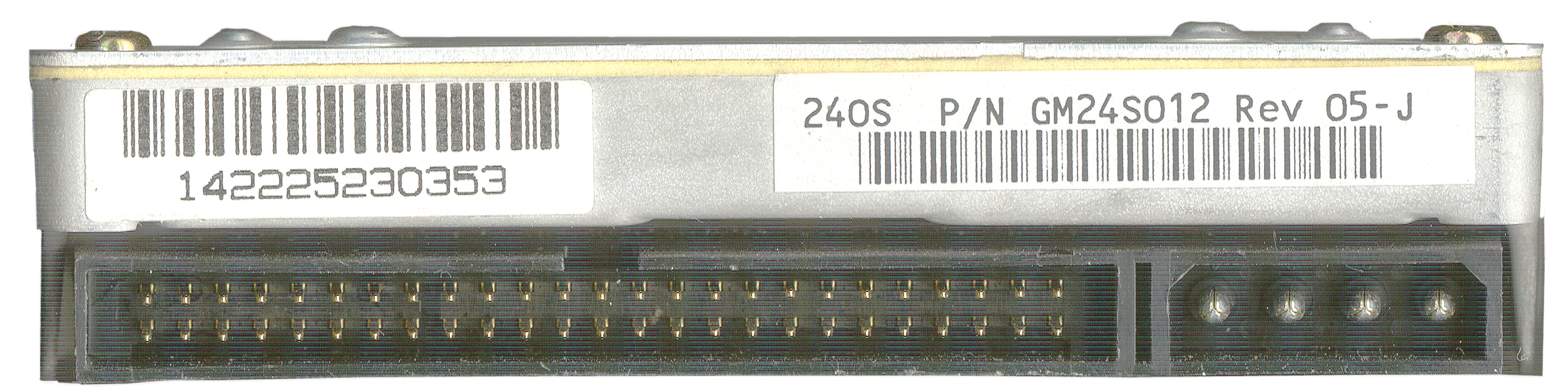
Fig 26 Hard Drive Stack: Desktop, Laptop,
PCMCIA,
Compact Flash

|
Fig
27
Compact Flash
|
Fig
28
PCMCIA
|
Fig 29 HP
C2985A Laptop IDE
|
Fig
30
Desktop IDE
|
Fig
31Viper
Drive in Adapter to IDE.
|
Card adapts PCMCIA (PC Card)
to
IDE.
Same connectors as Desk Top Hard Drive
|
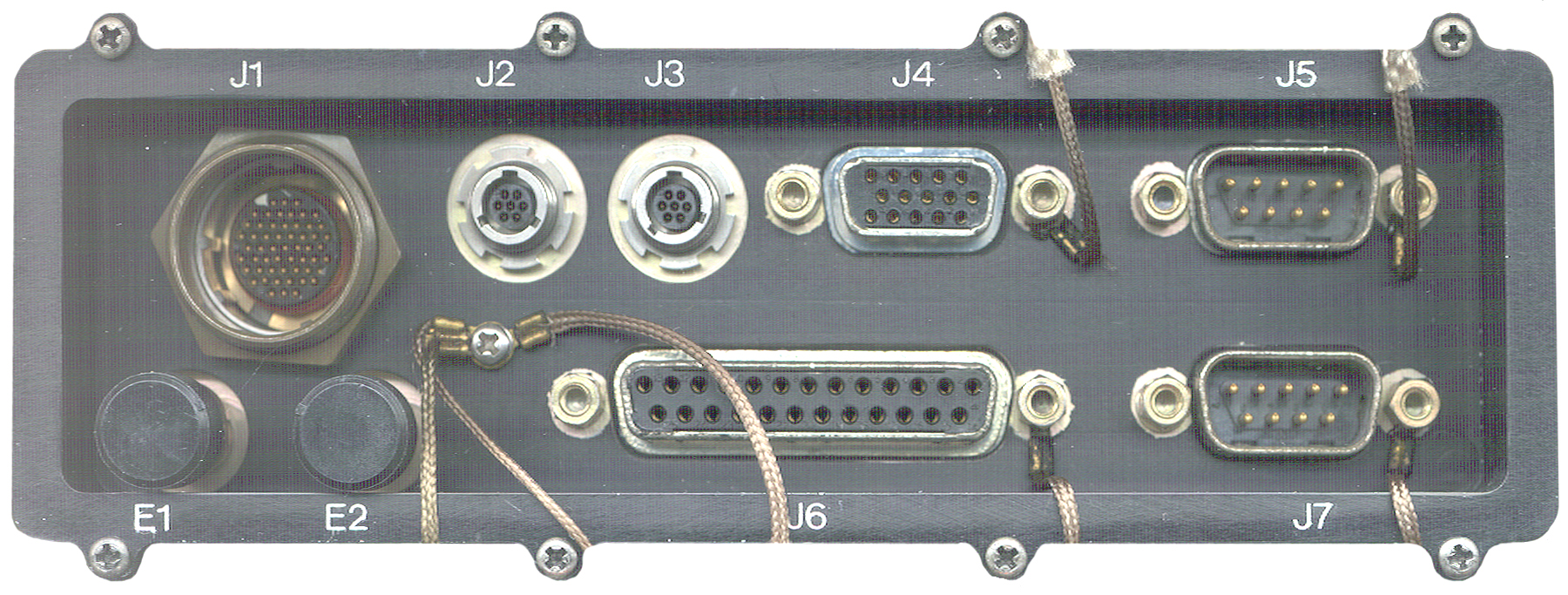
Connectors
ID
|
Contacts
|
Description
|
Function
|
J1
|
55
|
military
circular
connector, external screw threads, shrouded male pins,
#/row=
3, 6, 7, 8, 7, 8, 7, 6, 3
|
Dual
Modem 1
|
J2
|
7
|
circular
connector,
external screw threads (not
push on LEMO)
What are these connectors & where to get plugs?
|
External
DC
Power |
J3
|
7
|
"
|
PS2 |
J4
|
15
|
DB-15-f
|
VGA
Video Mon
|
J5
|
9
|
DB-9-m
|
COM1
|
J6
|
25
|
DB-25-f
|
Printer/parallel
|
J7
|
9
|
DB-9-m |
COM2
|
| E1
& E2 |
2
|
wire
line
spring binding posts
|
protocol
2
|
Note
1
- By using a local radio/SINCGARS cable two way digital
messaging can
be done. What is that cable?
Note 2 -for single channel
communications.
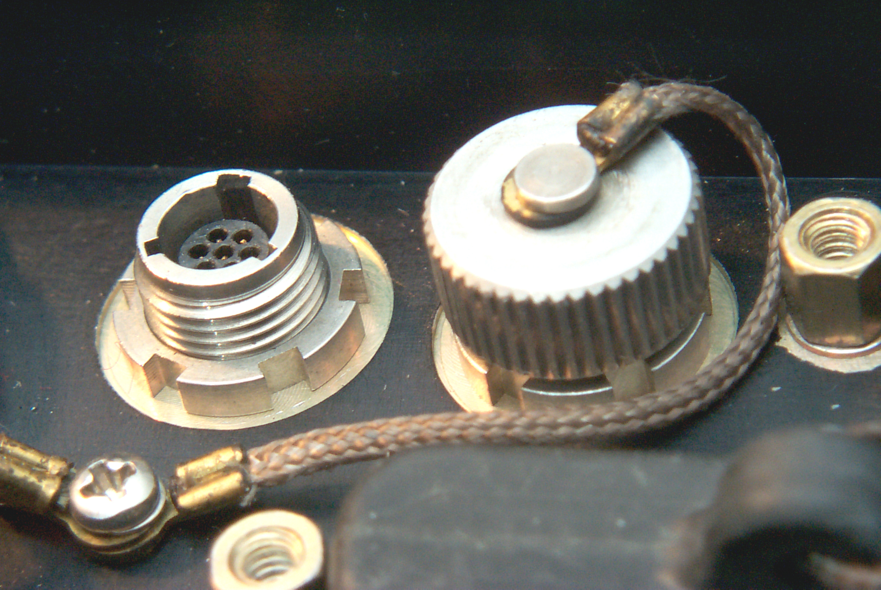
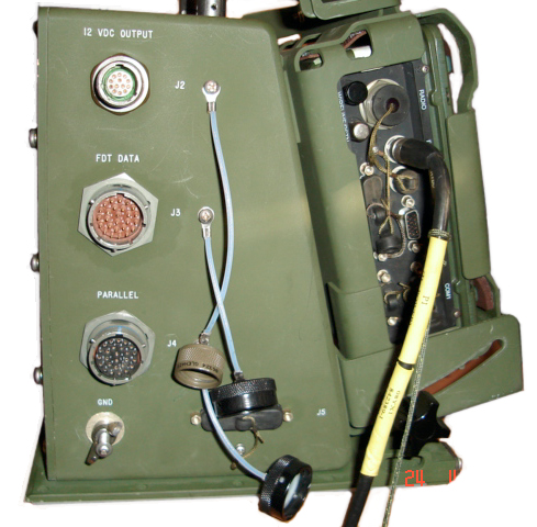
What is the J2
Connector?
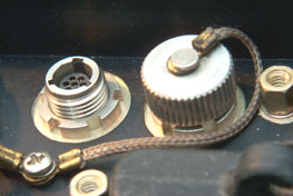
Fig
33 J2 Connector
The connector with the cap off is J2 used for external DC
power.
It has 7 terminals (hard to say if they are male, female or
both).
The mating plug will have a body diameter of about 0.216" and 3
projecting lugs.
What is this Connector?
The three pins (top row left, middle row left and center) are
the
ground connections.
The bottom row two pins are the +8 Volt connection.
What connector family and plug to make external power cable?
J3 just to the right of J2 has different keying, see Fig
3 Connector Assembly above.
William Perry has found a LEMO connector
that
has the correct insert, but the connector does NOT mate, only the
insert.
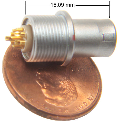 |
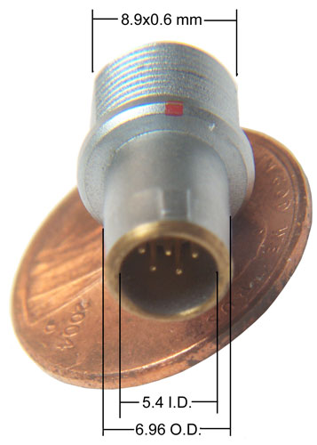
|
April
Note that this is the correct insert, but NOT the correct
connector. The barrel O.D. of 6.96mm is larger than
the I.D. of
J2 so will not fit.
I'm looking into using the insert to make a plug that would
mate to J2
(or J3).
If you are interested let me know.April
2009
|
Fig 32 External Power Wire
22
Mar
2008 - This shows the hot wire mod to get power to J2 until the
proper connector is located. A couple of tie wraps to take
any
strain off the solder only joint. With this connection you
can
see the BIOS boot then the LCD goes into invisible mode.
I started to use my laptop to load a PCMCIA hard drive, but the
laptop
only accepts the Type I cards (5 mm) and the hard drive is a
little
over 10 mm high. A PCI card for the desktop is on
order.
Just
above the second bottom philips head screw from the right there's
a SMT
version of a TO-220 package that contains a 340 power Schottky
diode with it's anode connected to the same terminal as the
red
wire and it's cathode connected to the big connector just above
it. The 8 lead IC just to the right and up from the 340 may
be a
power transistor. All four top pins are connected to
the
battery positive pin and the lower left three pins are connected
to the
same row of pins on the big connector as the BD340 diode.
There's
a SOT-23 FET just to the left of the BD340 that connects to the
lower
right pin on the 8 lead package. These parts form the
selection
circuit that uses the external power as a primary supply and if it
fails switches over to the battery.
J1 Modem Connector Pinout
When the keyway is at top center the
PSG-9 pins are numbered left to right 1, 2, 3 for the first row, 4
through 9 for the second row, etc.
The
SINCGARS
(
RT-1439)
(also see
U-229 family Pin Out) cable is wired:
SINCGARS
DATA
Conn
|
SINCGARS
Function
|
PSG-9
J1
|
PSG-9
Function
|
A
|
Ground
|
31, 43,
55
|
Ground
|
B
|
Spkr
data out
|
50
|
Data In
|
C
|
PTT
|
2
|
Key Tx
|
D
|
Mike In
Data In
|
12
|
Data
Out
|
E
|
Digital
Data
Mode Select |
7
|
Set D.
Mode
|
F
|
Analog
Data
Mode Select |
9, 42
|
Set A.
Mode
|
Controls &
Indicators
There are two button groups to the
left
and right of the screen.
When the two bottom bars are pressed and both held for about 1/2
second
the power comes up.
The shorter bars above those are used for screen navigation.
The LCD screen is 4.5" hi by 6" wide, about a 7 3/8" diagonal
640x480
VGA color
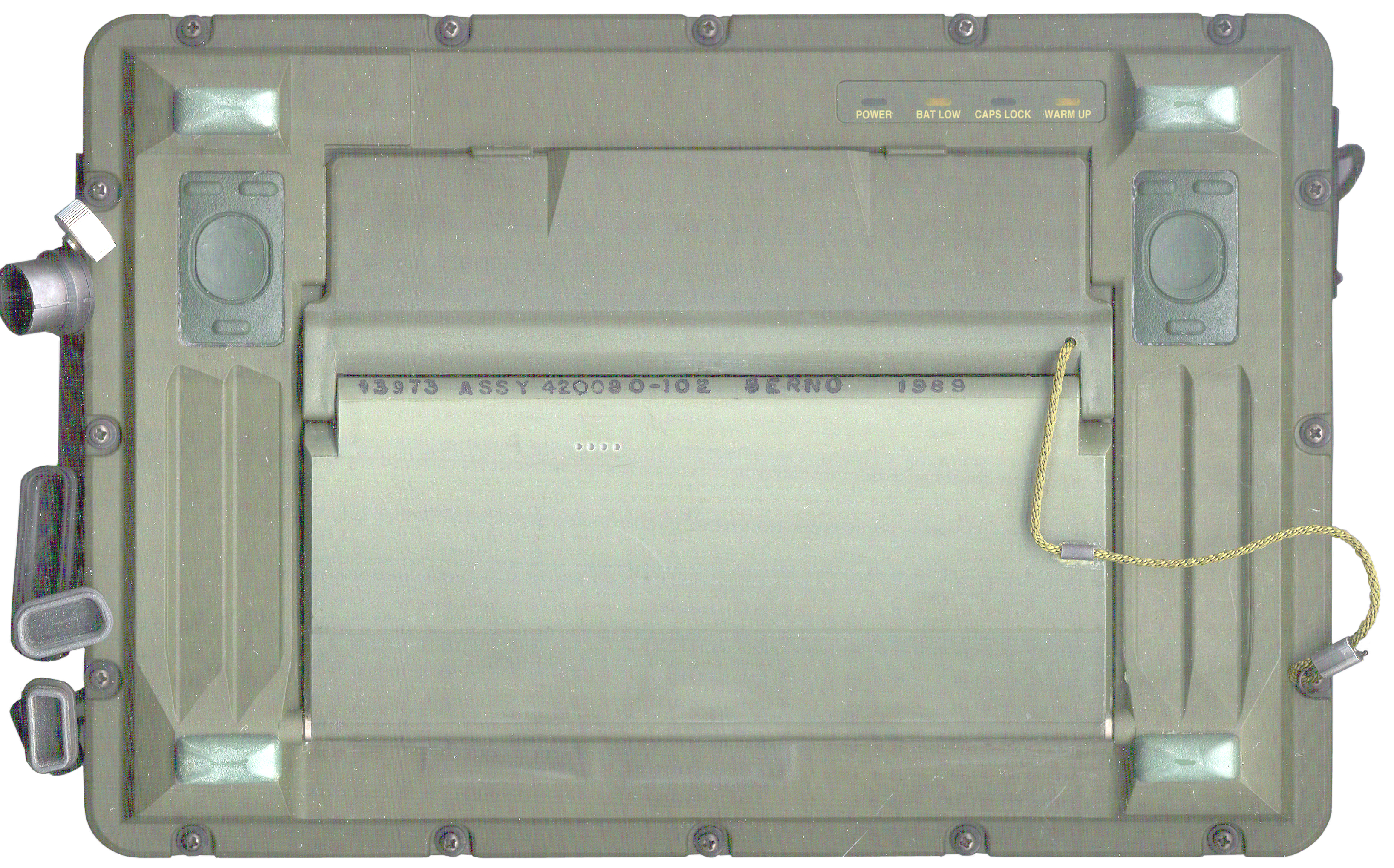
When the keyboard/LCD cover is closed the 4 indicator LEDs are
still
visible:
POWER
BAT LOW
CAPS LOCK
WARM UP
Modem Protocols
The internal modem supports the
Ground/Vehicle Laser Locator Designator (G/VLLD) IAW MIS 34269F
over a
high speed synchronous data port.
STANAG 4202 Transmission
Characteristics for Data Exchange between Land Tactical Data
Processing
Equipment over Single Channel Radio Links
MIL-STD-188-110A Interoperability and Performance Standards for
Data
Modems
ACCS-A3-407-008C Interface Specification for the Army Data
Distribution
System (ADDS) Interface
Applies to EPLRS
This seems strange. I would expect the PRC-77 and VRC-12 to
have
the same capability as far as data is concerned, but not the
PRC-126
since there's no mil std connector that gives acess to the wide
band
capability, it can only be used with the KYV-2/SVM-68. All
SINCGARS radios have a number of data modes and so might be in
multiple
catagories.
Manuals
All the manuals are in the "D"
folder
and so are not public information at this time.
TB 11-7021-228-10-1
FORWARD OBSERVER SYSTEMS (FOS)
HTU
(SOFTWARE VERSION 7.0)
HTU (DIGITAL DATA SET AN/PSG-9) (NSN 7035-01-452-4306)
LCU (FIRE CONTROL SYSTEM AN/GYK-37) (NSN 1230-01-380-9228) AND
RHC (DIGITAL DATA SET AN/PSG-11 (NSN 7021-01-491-9157)
TB 11-7021-228-10-2
FORWARD OBSERVER SYSTEMS (FOS)
(SOFTWARE VERSION 7.0)
HTU (DIGITIAL DATA SET AN/PSG-9) (NSN 7035-01-452-4306) (EIC:
N/A) <- spelling s.b. Digital
LCU (DIGITAL DATA SET AN/GYK-37 (NSN 1230-01-380-9228) (EIC:
N/A)
RHC (DIGITAL DATA SET AN/PSG-11) (NSN 7021-01-491-9157)
TB 11-7021-228-10-3
FORWARD OBSERVER SYSTEMS (FO/FIST
AND
FSO/CDR) SOFTWARE VERSION 7.0
RHC (DIGITAL DATA SET AN/PSG-11) (NSN 70210-01-491-9157),
LCU (FIRE CONTROL SYSTEM AN/GYK-27 (NSN 1230-01-380-9228),
HTU (DIGITAL DATA SET AN/PSG-9) (NSN 7035-01-452-4306)
TB 11-7021-228-10-4
OPERATORS REFERENCE MANUAL
FORWARD
OBSERVER SYSTEMS (SURVEY OPERATIONAL MODE)
HTU (DIGITAL DATA SET AN/PSG-9) (NSN 7035-01-452-4306)
RHC (DIGITAL DATA SET AN/PSG-11 (NSN 7021-01-497-9157
TM-9-6675-349-12-P
SURVEYING INSTRUMENT AZIMUTH:
IMPROVED
POSITION AND AZIMUTH DETERMINING SYSTEM (IPADS) XM111 NSN:
6675-01-515-4610 P/N: 7050004-9 INCLUDING
CPNU WITH CONTAINER (6605-01-521-7884)
BCU WITH CONTAINER (6130-01-521-6921)
CDU WITH CONTAINER (7010-01-521-7882)
TM 11-7021-225-12&P
OPERATOR’S AND UNIT MAINTENANCE
MANUAL
(INCLUDING REPAIR PARTS AND SPECIAL TOOLS LISTS),COMPUTER,
DIGITAL,
NSN 7021-01-444-9260 (EIC: N/A) V3 HANDHELD TERMINAL UNIT
- the
V3 looks very similar to the PSG-9
Reference
IPADS
The M111 Improved Position
andAzimuth
Determining System (IPADS) is a High Mobility Multipurpose
Wheeled
Vehicle (HMMWV)-mounted, inertial navigation surveying system,
which
will be used by artillery survey parties as a secure,
all-weather,
day-night means for rapidly extending survey control to satisfy
the
demands of mobile weapons systems. IPADS, which does not
rely on
Global Positioning System (GPS), accurately aligns GPS-aided,
self-locating firing elements on a common survey grid, enabling
these
firing elements to mass fires. IPADS will provide a highly
mobile
and accurate means of performing artillery survey. IPADS
will
determine location coordinates, altitude in meters, direction in
millimeters (typo?) ,and will be capable of rapid and accurate
self-alignment utilizing ring-laser gyros and
accelerometers. The
IPADS will replace the currently fielded AN/USQ-70 Position and
Azimuth
Determining System (PADS) in all Marine Corps artillery units.
CA-5033/UYC Printer
The same Canidian eBay seller that
was
selling the PSG-9 also had this printer. Maybe they are
related
and manbe not?
It's 7 x 7 x 5 inches and the roll paper is 4 1/4" wide and I'm
sure
it's dot matrix to support both text and graphics.
Controls and Indicators
On the front there is a combined ON-OFF switch that's also a
circuit
breaker. When switched on with a battery installed the LEDs
flicker and go off and the paper feeds.
LEDs for:
ON LINE
POWER
FAULT
LOW BTY
Two push buttons:
TEST - prints a test pattern
LF - Feeds a line of paper
When LF is pressed and held and TEST is also pressed (BRIGHT) the
POWER
ON LED brightenes and it seems continionous paper is fed.
That
may be a problem or may be related to not having anything
connected to
the data input.
Connectors
On the back there are two connectors and a tapped hole for a
ground
marked E1 GND.
Circular bayonet locking.
J1 POWER
MS3470W14-5P
5 male pins in a "W" shape.
Pins marked A, B, C, D, E & F
[ cap MS3181-14CA]
The J1 POWER connector has a low diode drop from J1-A to battery
pin 5
and from J1-C to battery pin 5. Battery pin 5 is the "A"
side
positive
terminal.
J1-B connects to J1-D and these connect to battery pin 3.
Battery
pin
3 is connected to battery pin 1 ("B" side minus) only on
rechargable
batteries and so is a selective way of charging only rechargable
batteries and not charging primary batteries like the
BA-5590/U.
Battery pin 2 is jumpered to pin 4 so the battery is being used as
a 24
volt (30 V full charge/fresh to 10 volt dead).
29 March 2008 - my day one guess is that B & D are ground and
A
& C are +28 VDC.
J2 DATA
MS3470W10-6P
6 male pins.
Pins marked A, B, C, D, E & F
[cap MS3181-10CA]
There are 6 wires from the back of J2 they are (in pin number
order)
Wht, Blk, Wht, Blk, Wht, Blk.
Pin 1 on PCB is J2-A and Pin 6 on the PCB is J2-F
Battery
The internal battery is one of the
BA-5590
family.
Fig 34 Printer Battery Compartment
|
On
the left side there are two screws that can be backed out
a few turns
then the battery door slides to the left (no need to
remove the screws).
A BA-5590 battery is connected to the cable plug and the
plug end fed
in first. My 5590BA will also work.
I have the cover off which had three seals that were
already
broken. Front is to the right of this photo.
The PCB to the
right is the printer driver and the PCB near the battery
is the power
supply. There are 5 wires going to the battery
so it may
support rechargable batteries like the BB-390, BB-590,
BB2590, etc.
when external power is used. |
Printer Test
Fig 35 Printer Test Strip
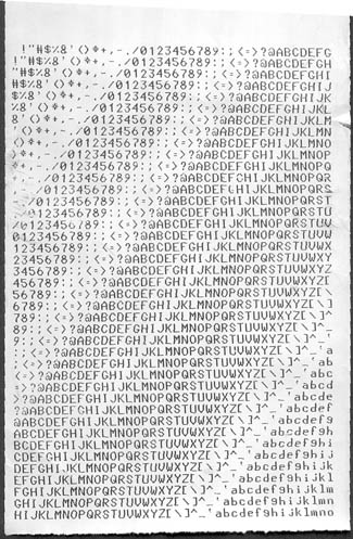 |
The
alpha numeric characte set inncludes the upper case
letters, lower case
letters, digits and 23 symbols for a total of 85
characters. The
test is 41 lines long and there are 40 characters across
the strip. |
Serial Printer Connector
Normal Computer DB-9m
connector:
Pin
|
Name
|
Dir
|
Volts
|
1
|
DCD
|
in
|
+0.1
|
2
|
Rx
|
in |
+0.1 |
3
|
Tx
|
out
|
-10.3
|
4
|
DTR
|
out |
-10.3 |
5
|
ground
|
gnd
|
0
|
6
|
DSR
|
in |
+0.1 |
7
|
RTS
|
out |
-10.3 |
8
|
CTS
|
in |
+0.1 |
9
|
RI
|
in |
+0.1 |
Note that the direction of the signal (Dir coul) is exactly
correlated
with the open circuit voltage on the pin.
Serial
Printer DB-9f (HP
LaserJet 4050)
This table has all the directions opposite of those in the
computer
table above.
Some of the names may be wrong.
Pin
|
Name
|
dir
|
Volts
|
1
|
Data
Carrier
|
out
|
+6.8
|
2
|
Tx
|
out
|
-6.4
|
3
|
Rx
|
in
|
0
|
4
|
Terminal
Ready
|
in
|
0
|
5
|
ground
|
gnd
|
0
|
6
|
DSR
|
out
|
+7
|
7
|
CTS
|
in
|
0
|
8
|
RTS
|
out
|
+6.9
|
9
|
Ring
Indicator
|
out
|
0
|
A minimal connection would be pins 2, 3 and 5. The next most
common would include CTS/RTS so would have pins 2, 3, 5, 7 & 8
which is 5 pins and so may be what the CA-5033 uses.
The HP LaserJet has the following voltages for those 5 pins: -6.4,
0,
0, 0, +6.9.
CA-5033-J2
Blk
v
Red->
|
A
|
B
|
C
|
D
|
E
|
F
|
A
|
x
|
+9.6
|
+18.9
|
+9.6
|
+9.6
|
+9.6
|
B
|
-9.6
|
x
|
+9.3
|
0
|
0
|
0
|
C
|
-18.9
|
-9.3
|
x
|
-9.3
|
-9.3
|
-9.3
|
D
|
-9.6
|
+9.3
|
+9.3
|
x
|
0
|
0
|
E
|
-9.6
|
0
|
+9.3
|
0
|
x
|
0
|
F
|
-9.6
|
0
|
+9.3
|
0
|
0
|
x
|
The A-C voltage of almost 19 seems too high so the ground pin is
not A
or C.
The data is symmetrical about the diagonal.
Looking for rows that have three zeros and one each + and one each
-
voltage yeilds:
B, E or F as possible ground pins.
Vehicle Mount
Related
PSC-2A Digital Message DevicePSG-2
Digital
Message Device
Manuals
TM 11-7440-281-
Cable
CX-13308
Battery
BA-5600, BB-2600 (same as the PSG-9)
PSG-5
AN/PSG-5 Fire Support Team Digital
Message Device.
(FIST DMD), a field communication terminal developed to support
forward fire control on the batttlefield.
Manuals
TM 11-7025-244-12&P
TM 11-7025-244-30
TM 11-7025-244-30P
FM 6-30 TACTICS, TECHNIQUES, AND PROCEDURES FOR OBSERVED FIRE,
App B
Cable
CX-13308
Baattery ??
PSC-6 Digital Imaging Set -
Links
Back to Brooke's List of all web pages in
alphabetical order, Products for Sale,
Military Information, PRC-68
Family
of Squad Radios, U229 Audio
Accessories, Audio Connectors, Electronics, Home
page
[an error occurred while processing this directive] page created 28 Feb
2008.