Definition
To be called a Joule Thief I think a circuit needs to be able to start when it's input voltage is below 1.0 Volt. That's because one volt is one of the definitions of a dead single cell battery. So if a circuit can start up on less than that it's stealing energy that would have been thrown away if the "dead" battery was put in the hazardous waste. The lower the starting voltage the more energy a circuit is capable of stealing. But coupled with low starting voltage a circuit needs to have enough output current to do something useful, like lighting a LED or powering something useful. For example there are some MOSFETs that can be used to make a multivibrator that will start at 0.16 Volts, but if it can't drive anything that circuit is not a Joule Thief.A blocking oscillator (Wiki) is a circuit that can be made into a Joule Thief by selecting parts that allow low voltage starting and is the most common circuit.
Most inverter circuits will not start at low enough voltages to be called a Joule Thief.
The Joule Thief is very similar to the Flyback Converter (Wiki) but it does not have metallic isolation between the input and output.
The Forward Converter (Wiki) is more efficient than the Flyback Converter.
4734658
4696639 Self-energizing Burner Control System for a Fuel Burner,
EEVblog #664 - Peltier TEG Energy Harvesting Experiments - LTC3108 data sheet has info for 100:1 transformer suppliers.
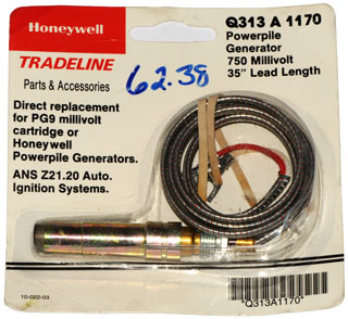
Honeywell Powerpile 750 mV thermopile (Wiki) (see my battery page for output data)
These are used to supply electricity to a heating gas control valve by means of a thermostat and are powered by a gas pilot flame. So the heating is independent of the AC mains power.
Alternatives or additions to Blocking
Oscillator (flyback oscillator)
There are some circuits used with very small solar cells to
power motors that make use of a voltage detector IC such as the
Panasonic MN1381, Maxium MAX8212, Microchip TC54, etc.
These CMOS circuits close a switch to ground when the voltage
falls below some minimum voltage (they come in many voltages or
allow setting the trip point with external resistors).
This way an energy storage capacitor can be charged by the very
small solar panel then discharged into the load. An
example is the MSE2.
Note that the solar panel is connected directly across the
storage capacitor.
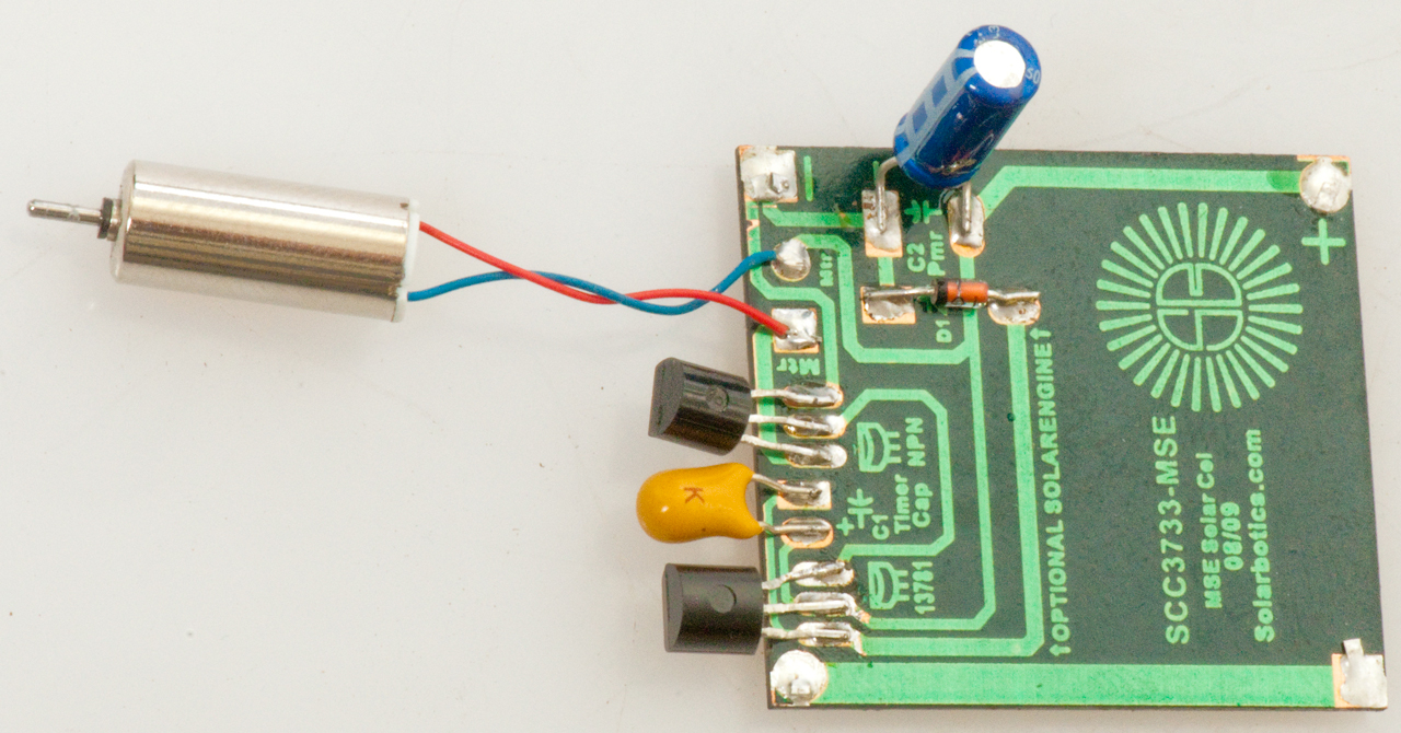
Miller Solar Engine Solarbotics.com
|
 |
| The Panasonic poly crystal solar cell
generates electricity even when it's cloudy. The
motor runs once every six minutes for about six
seconds. When in direct Sun the motor runs for about
six seconds with a pause of a few seconds. Note: the business card size assembly instructions were for a different version MSE and incorrectly showed the two TO-92 components with the flats up. You can see (click photo for a larger version) that the diagram on the board shows the flats down. |
The Brown Fluxgate patents are based on a blocking oscillator that's modified to use less power, prolong battery life.
Note an induction coil generates a back EMF or kick when it's drive current is interrupted. Automobile spark ignition engines use "spark coils" to step up the vehicle low voltage DC to many kilovolts to fire the spark plugs.Flip Flap Solar
Note that the energy storage capacitor is in parallel with the
solar cell in the Miller Engine. Solar cells deliver
current that's directly proportional to the light level into a
short, so the current causes the capacitor voltage to ramp
up. When it gets to some preset voltage the trigger
circuit connects the capacitor to the load. This way loads
that take currents much higher than the solar cell can supply
can be used, but on an intermittent basis.
Big Clive:
| Fig 1 When in direct sun it runs all the
time. But, when indirect light it waits then runs for a short time. = Miller Engine.  |
Fig 1 Large capacitor (470 uF 10V) stores
energy until a set voltage then it is connected to the load. 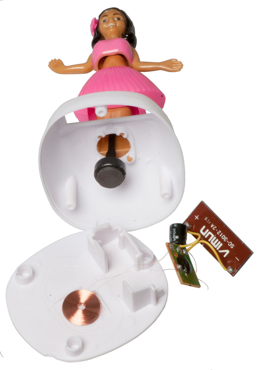 |
There may be some history relating Flip Flap Solar mechanisms to
Also See Quartz Clock patents, Pendulums, Time & Frequency,
ADI engineering Solar powered motion toy tear-down - The needed plot is the voltage across the capacitor/solar panel. I expect the trigger voltage to be the same under different light conditions.
@:4:13 Big Clive comments on schematic.
S9014 silicon NPN TO-92
8550 silicon PNP TO-92
? coil data ?

Kundo ATO
Electromagnetic "Electric Clock"
This may be the first electromagnetic pendulum
driven clock to use a transistor (Wiki,
Wiki).
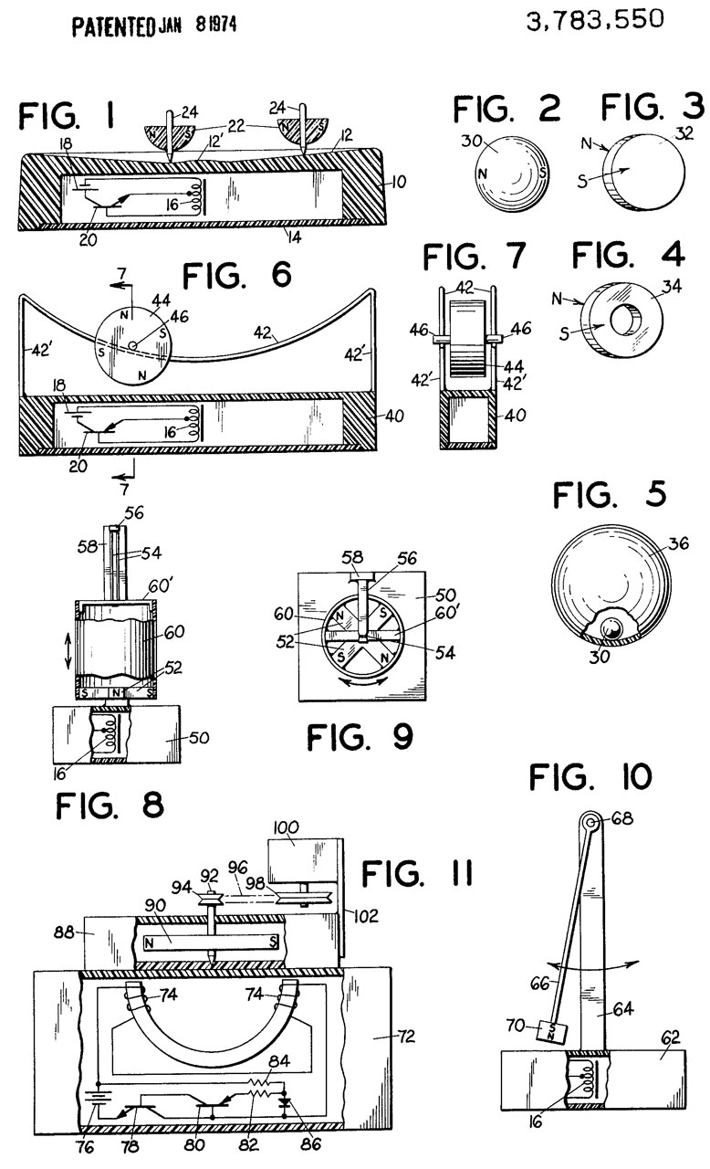
See the 1961 US patent 2974265 below that applies to this clock as well as other patents in that table. It preceded the 1974 US patent 3783550 for the Novelty Electric Motor by a dozen years which in turn came before the Flip Flap Solar figures.
Started at 2:56pm 9/13/2019 now to wait and see what the rate is for my local gravity. Note that all clocks that are regulated by a pendulum are also measuring the local value of gravity. To get them to tell accurate time they need to be adjusted. I expect the end user's gravity will pretty much never be the same as the gravity at the clock factory.
At 4:27 the Kundo shows 4:29, so running 2 minutes fast in 91 minutes i.e. 2/91= .0219
Saturday 9/14/2019 @2:00pm the Kundo shows 2:18pm, 18 minutes fast. i.e. 18/1384 = 0.1300
Sunday 9/15/2019 @2:40pm the Kundo shows 3:15 pm The actual time has advanced a day (1440min + 40 = 1480 minutes) and the Kundo time has advanced a day & 57 min (1440 + 57=1497 min), so rate = (1497-1480)/1480=0.0115.
| Date - Time | Delta | Kundo | K. delta | delta Fast | Rate |
| 9/13/19 14:56 | min | 9/13/19 14:56 | min | min/day | |
| 91 | 93 | 2 | 31.6 | ||
| 9/13/19 16:27 | 9/13/19 16:29 | ||||
| 1293 | 1309 | 16 | 17.8 | ||
| 9/14/19 14:00 | 9/14/19 14:18 | ||||
| 1480 | 1497 | 17 | 16.5 | ||
| 9/15/19 14:40 | 9/15/19 15:15 | ||||
| 1475 | 1493 | 18 | 17.6 | ||
| 9/16/19 15:15 | 9/16/19 16:08 | ||||
| 1383 | 1400 | 17 | 17.7 | ||
| 9/17/19 14:18 | 9/17/19 15:28 | ||||
| 1366 | 1380 | 14 | 14.8 | ||
| 9/18/19 13:04 | 9/18/19 14:28 |
| Date - Time | Delta | Kundo | K. delta | delta Fast | Rate |
| 9/21/19 13:47 | min | 9/21/19 13:47 | min | min/day | |
| 1717 | 1731 | 14 | 11.7 | ||
| 9/22/19 18:24 | 9/22/19 18:38 | ||||
| 1330 | 1344 | 14 | 15.2 | ||
| 9/23/19 16:34 | 9/23/19 17:02 | ||||
| 1264 | 1274 | 10 | 11.4 | ||
| 9/24/19 13:38 | 9/24/19 14:16 | ||||
| 1447 | 1461 | 14 | 13.9 | ||
| 9/25/19 13:45 | 9/25/19 14:37 |
Adjustment
Lowered bob one full turn (12 tick marks) and slightly raised the pawl and shimmed the right side of the case so pendulum swing is more symmetrical.Restarted at 9/18/2019 13:15 with hands reset.
Too Much Voltage?
I've made two more attempts to regulate the clock and it's still running 14 min/day fast. It may be the case that using a L91 Lithium AA battery is too much voltage and is overpowering the motor? The L91 starts out at 1.7 Volts and stays above 1.5 Volts for a long time. The E91 Alkaline AA battery starts at 1.5 Volts and goes down from there much faster. As it is the clock makes a "thump" sound when the pendulum is all the way left or right, depending on the left to right leveling adjustment. There is not sweet spot where the "thump" goes away.Photos
Fig 1 Clock in glass case. |
Fig 2 Front: Glass case removed (note open
clips and holes for case pins). |
Fig 3 Back |
Fig 4 1.5 Volt Battery came separately
wrapped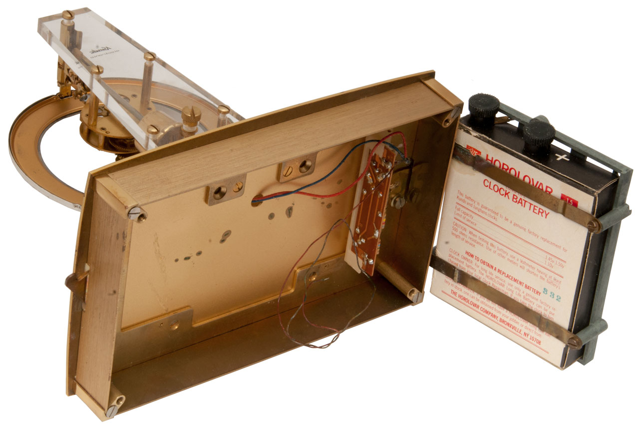 |
Fig 5 Two PNP transistor circuit. It's not clear if the metal case is part of the electrical circuit. Only a red and black wire come from the two coils. 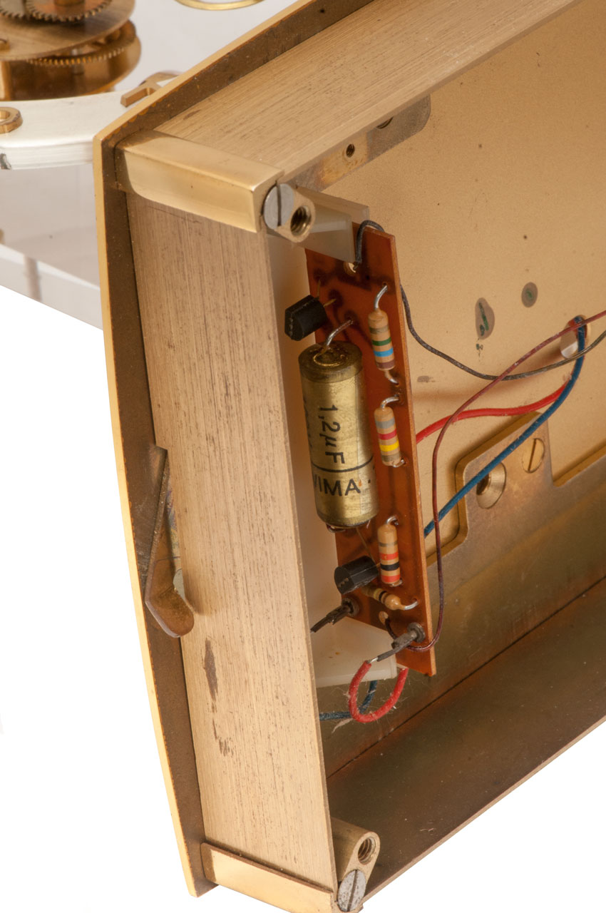 |
Fig 6 Left Reat including temperature
compensated top tube.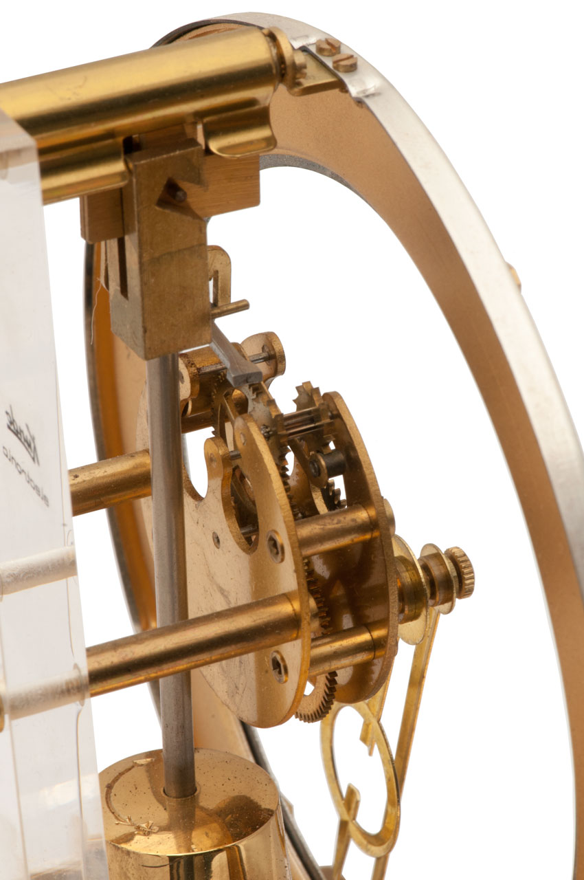 |
| Fig 7 "Kieninger & Obergfell, Made in
Western Germany". Germany was divided between 1945 and 1990 (Wiki). 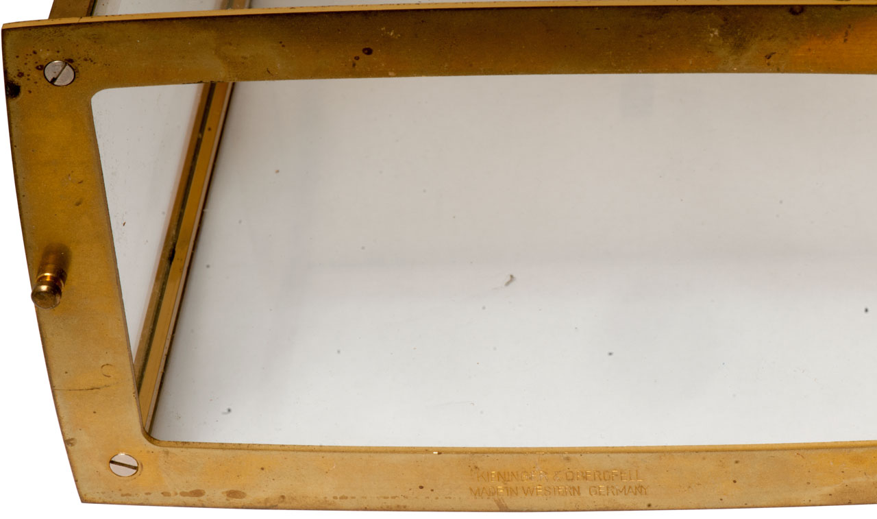 |
Fig 8 "Kundo Electric" "Made
in Germany" There is a space between "in" and "Germany" caused by the bottom of the numeral "6". 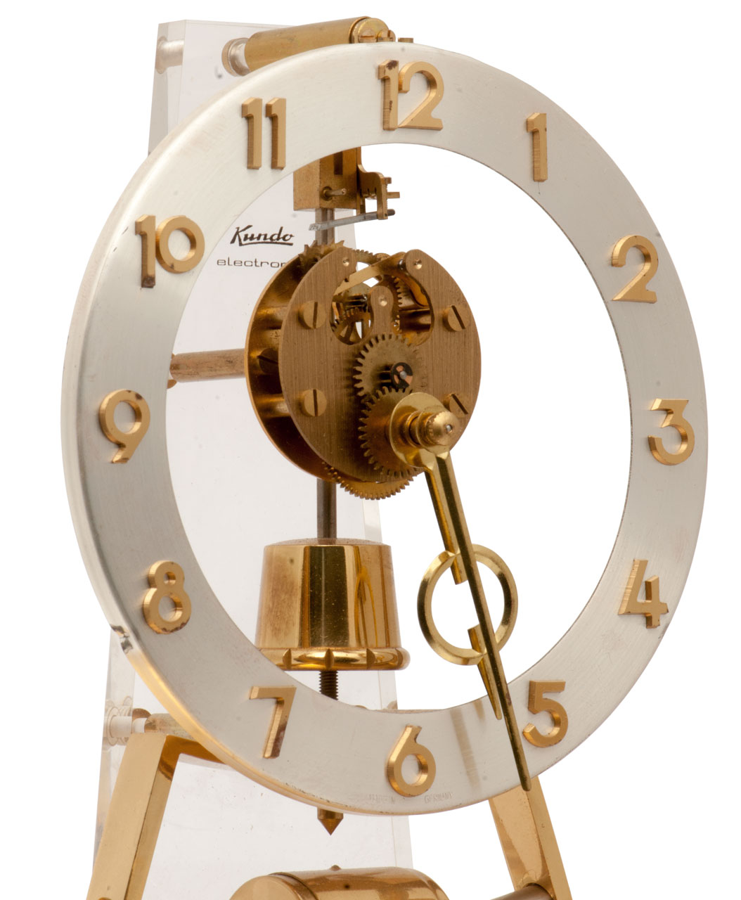 |
Fig 9 Front close up |
Fig 10 Front close up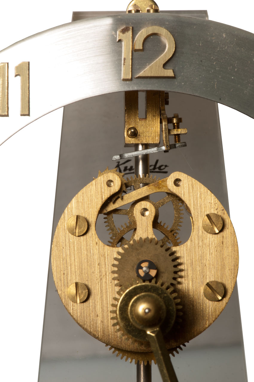 |
Fig 11 Right Side: Pendulum locked as received from shipping. Note pendulum is lifted from normal position. temperature compensated top tube 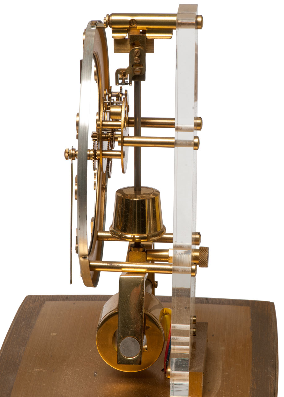 |
YouTube: https://youtu.be/9EK1MLA6igk |
| Fig 12 Horolovar long life Clock Battery
1.5 Volt The Horolovar Company: Size 8 or 9 Dual Prarllel AA battery adapter  |
Fig 13 Back side. Note mounting screw
at lower right. This mounting bracket probably fits a number of Kieninger & Obergfell clocks in addition to this one. 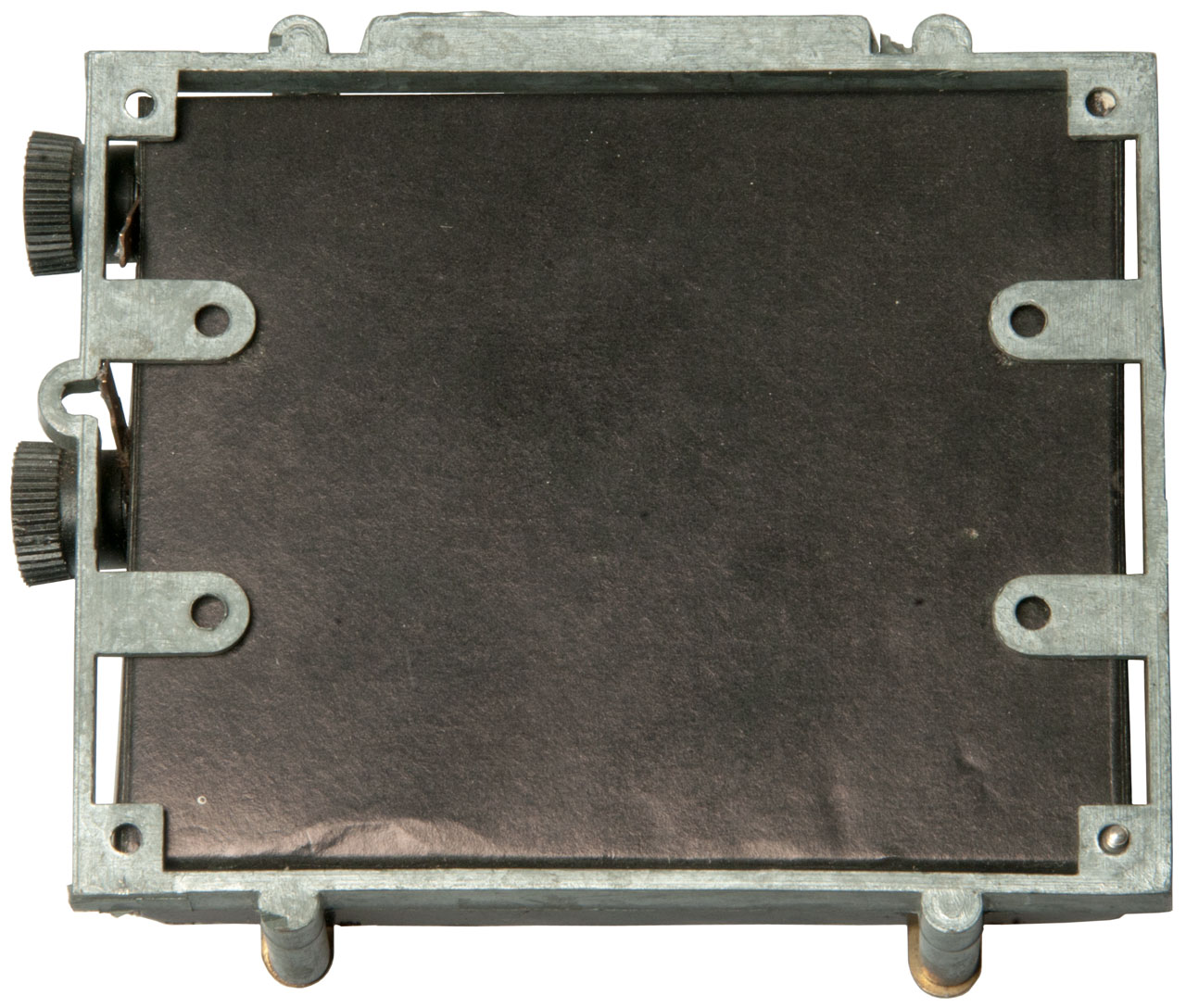 |
Fig 14 (from eBay) showing how the battery
holder mounts. Also note the leveling feet. Need to determine thread spec.  |
Patents |
FR375188A (eSpaceNet) Pendule électrique libre sans échappement ni rouages, Charles Fery, 1907-03-01, - | |
| 1970412
Means for opening and closing circuits at regular
intervals, Clifford
V Bates, 1934-08-14, - |
||
 |
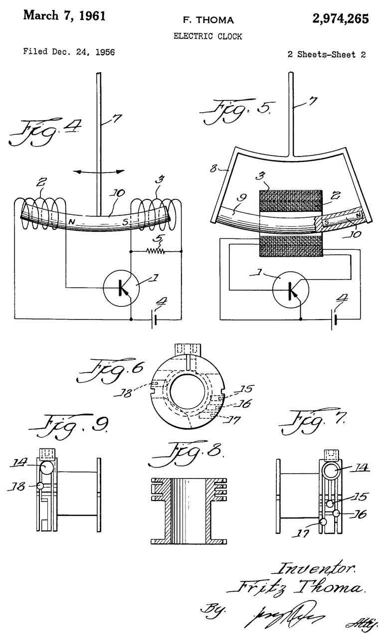 |
2974265 Electric clock, Thoma Fritz, Kieninger and Obergfell, March 7, 1961, 318/132 368/157 310/32 446/484 968/463 - Kundo ATO Electronic Clock Cites: Publication number Priority
date Publication date Assignee Title
US537769A *1895-04-16
harbison - electric meter that uses a pendulum, with
coils disposed in a similar fashion, but not at all a
clock.
FR986536A *1949-03-11
1951-08-01 Hatot Leon Elselectric and
advanced clock systems Clocks - This is a very similar
mechanism, but seems much more complex and it uses
mechanical contacts.
US2644893A *1952-06-02
1953-07-07 RCA Corp Semiconductor pulse memory
circuits
US2695381A *1952-07-241954-11-23
Foxboro Co Follow-up type of measuring apparatus
FR1090564A *1953-09-171955-03-31Hatot
Leon Ets Improvements to schedules mechanisms
and similar apparatus - most likely a development of
FR986536A.
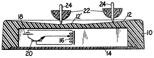
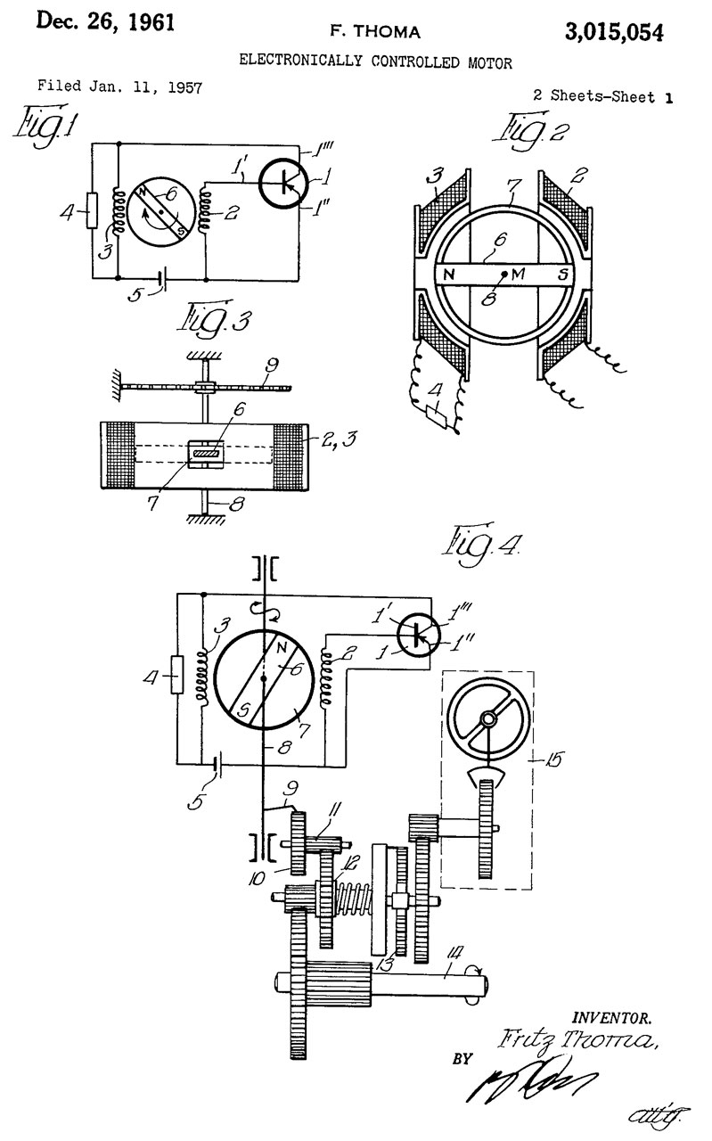
Note these use PNP transistors and run from a 1.5 V battery. The circuit is very similar to the Novelty Electric Motor which is dated 1974. Fig 5 Shows the generator (sense) coil (2) wound close to the armature (9) and the motor coil (3) would on top of the generator coil (2). Note the magnet (10) is near the right end of the armature (9). The right side of the armature on the clock shows as a North magnetic pole while there is no indication on the left side of the armature. A lot of effort went into arranging the components to maximize battery life and to correct for temperature effects on the transistor. Figures 2 & 3 show the transistor and resistor located inside the coil assembly so only the battery would be separately located making for a very clean design. The early patents in class 318/132 are related to electric jackhammers. Then come tuning fork related. |
 |
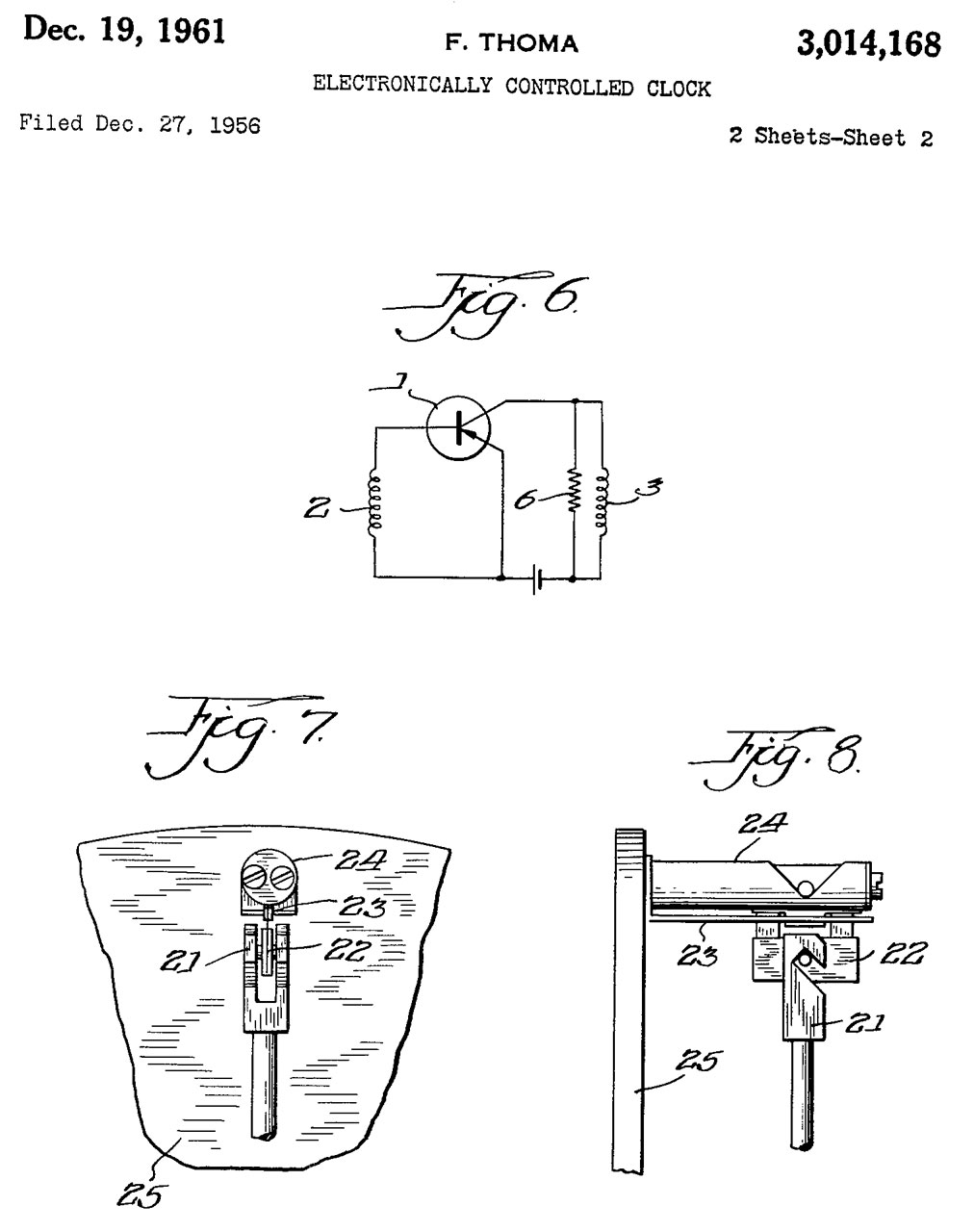 |
3014168 Electronically controlled clock, Thoma Fritz, Kieninger and Obergfell, Priority: 1955-12-28, 318/132; 310/15; 368/157; 968/476; 310/27 Patent Figures 7 & 8 relate to temperature compensating the pendulum using a bi-metal strip (23). See photo Fig 11 above. Notice in patent Fig 6 the stabilizing resistor (6) in parallel with the motor coil (3). |
 |
 |
3015054 Electronically controlled motor, Thoma Fritz, Kieninger and Obergfell, Priority: 1956-01-14, 318/47; 318/130; 310/46; 318/132; 368/158; 968/476; 318/400.26 |
| 3005305
Electric watch, Thoma
Fritz, Kieninger and Obergfell, 1961-10-24, - very
similar offset permanent magnet and 2 coils |
||
| 3168690
Clock power-device, Marius
Jean Lavet, Jacques
Jean Gustave Dietsch, Leon
Hatot SA, App: 1954-08-31, Pub: 1965-02-02, - |
||
| 3724200
Electronic clock with low power consumption, S
Donner, Kieninger and Obergfell, 1973-04-03, - for
use with solar cells. |
Patents related to Kundo, Kieninger and Obergfell
2831114 Transistor amplifier with bias stabilization, Adrianus Johannes, Wilhel Marie, Priority:
Cites:
Publication number Priority date Publication date Assignee TitleUS2680160A *1951-09-15 1954-06-01 Bell Telephone Labor Inc Bias circuit for transistor amplifiersFR1090564A *1953-09-17 1955-03-31 Hatot Leon Ets Improvements to schedules mechanisms and similar apparatusFamily To Family CitationsUS2647958A *1949-10-25 1953-08-04 Bell Telephone Labor Inc Voltage and current bias of transistorsBE505739A *1950-09-12NL167001B *1951-01-31 Koninkl Mij Tot Het Uitvoeren A process for dredging and transporting dredge species.
Cited by:
Publication number Priority date Publication date Assignee TitleUS2957116A *1957-06-14 1960-10-18 Hurd Lock & Mfg Company Mechano-electric clocksUS2962643A *1955-04-26 1960-11-29 Omega Brandt & Freres Sa Louis Time-pieceUS2970277A *1957-10-07 1961-01-31 Gen Motors Corp Bridge biasing transistor circuitUS2972114A *1957-12-23 1961-02-14 Motorola Inc Amplifier circuitUS3005958A *1958-06-26 1961-10-24 Statham Instrument Inc Temperature-sensitive bias networkUS3010075A *1958-09-10 1961-11-21 Hamilton Watch Co Electric watchUS3014168A *1955-12-28 1961-12-19 Kieninger & Obergfell Electronically controlled clockUS3015054A *1956-01-14 1961-12-26 Kieninger & Obergfell Electronically controlled motorUS3026458A *1957-07-11 1962-03-20 Siemens Ag Electric clock driveUS3054966A *1959-07-15 1962-09-18 Gen Electric Crystal controlled oscillator with temperature compensating meansUS3061784A *1958-12-22 1962-10-30 Motorola Inc Bias control circuitUS3095529A *1959-06-10 1963-06-25 Suisse Horlogerie Device for electromagnetically maintaining oscillating movementUS3095528A *1958-05-24 1963-06-25 Suisse Horlogerie Electromagnetic device for maintaining the oscillatory movement of a balance wheel comprising a hair springUS3112418A *1958-06-20 1963-11-26 Renault Devices for gradually establishing an electric current, notably for controlling electromagnetic clutchesUS3117265A *1959-07-11 1964-01-07 Movado Montres Electromagnetic system for the maintenance of the movement of a movable memberUS3149318A *1959-09-11 1964-09-15 Specialties Dev Corp Temperature compensated sensitivity control network for disturbance detecting apparatusUS3156857A *1958-12-17 1964-11-10 Herr Fritz Electrodynamic rate regulator arrangement for clocksUS3176171A *1961-03-14 1965-03-30 Suisse De Rech S Horlogeres La Electromagnetic oscillatory driveUS3178644A *1961-06-19 1965-04-13 Automatic Radio Mfg Co Transistor vehicular radio receiver operable over a range of power supply voltagesUS3195065A *1963-06-26 1965-07-13 Statham Instrument Inc Temperature stabilization of transistor amplifiersUS3277394A *1963-03-12 1966-10-04 United States Time Corp Temperature compensated electromechanical resonatorUS3351833A *1962-06-29 1967-11-07 Diehl Compensated transistorized electric clock circuitUS3356919A *1963-12-09 1967-12-05 Reich Robert Walter Transistor circuit for the operation of electronic clocksUS3359473A *1965-02-25 1967-12-19 Negri Emillio Self-starting electronic oscillating device for clockworksDE1801444B1 *1968-10-05 1970-07-23 Kienzle Uhrenfabriken Gmbh Electronic switchUS3524117A *1967-11-021 970-08-11 Reich Robert W Transistorized amplifier for electronic clockwork motorUS3530664A *1966-11-25 1970-09-29 Ebauches Sa Electronic timepieceUS4080552A *1976-09-22 1978-03-21 Facet Enterprises, Inc. Hybrid blocking oscillator for an electromagnetic fuel pumpUS4728871A *1985-11-01 1988-03-01 Andrews Roger W Novelty electric motorFamily To Family CitationsDE1207886B *1957-07-11 1965-12-23 Siemens Ag Electronic clocks driveBE572724A *1957-11-06DE1175160B *1958-01-08 1964-07-30 Smith & Sons Ltd S Time measuring deviceDE1235825B *1962-11-08 1967-03-02 Kienzle Uhrenfabriken Ges Mit electronic car clock
3040225
3100278 Electromagnetic pendulum drive, Reich Robert Walter, Aug 6, 1963,
Cites:
Publication number Priority date Publication date Assignee TitleUS2396224A *1943-06-16 1946-03-12 Rca Corp Oscillation generator - Vacuum Tube tuning fork
US2547027A *1948-01-02 1951-04-03 Motorola Inc Vibrating reed controlled oscillator - Tube type
US2692337A *1948-12-29 1954-10-19 Bell Telephone Labor Inc Oscillation generator - various transistor circuits
Cites:
2719944 Commutatorless direct current motor, Harrison D Brailsford, App: 1954-06-10
3225536 Electric clock, 1965-12-28 - electromagnet drives pendulum or balance wheel.
Solar Path Lights
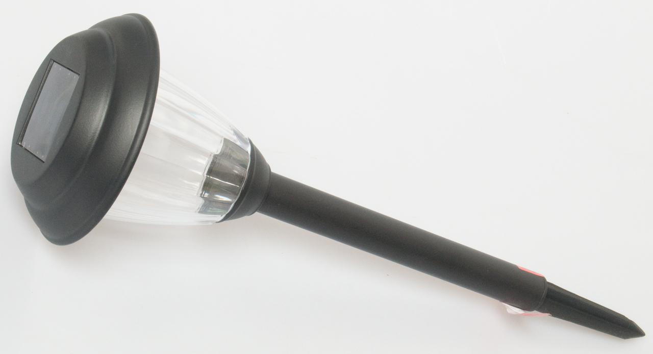
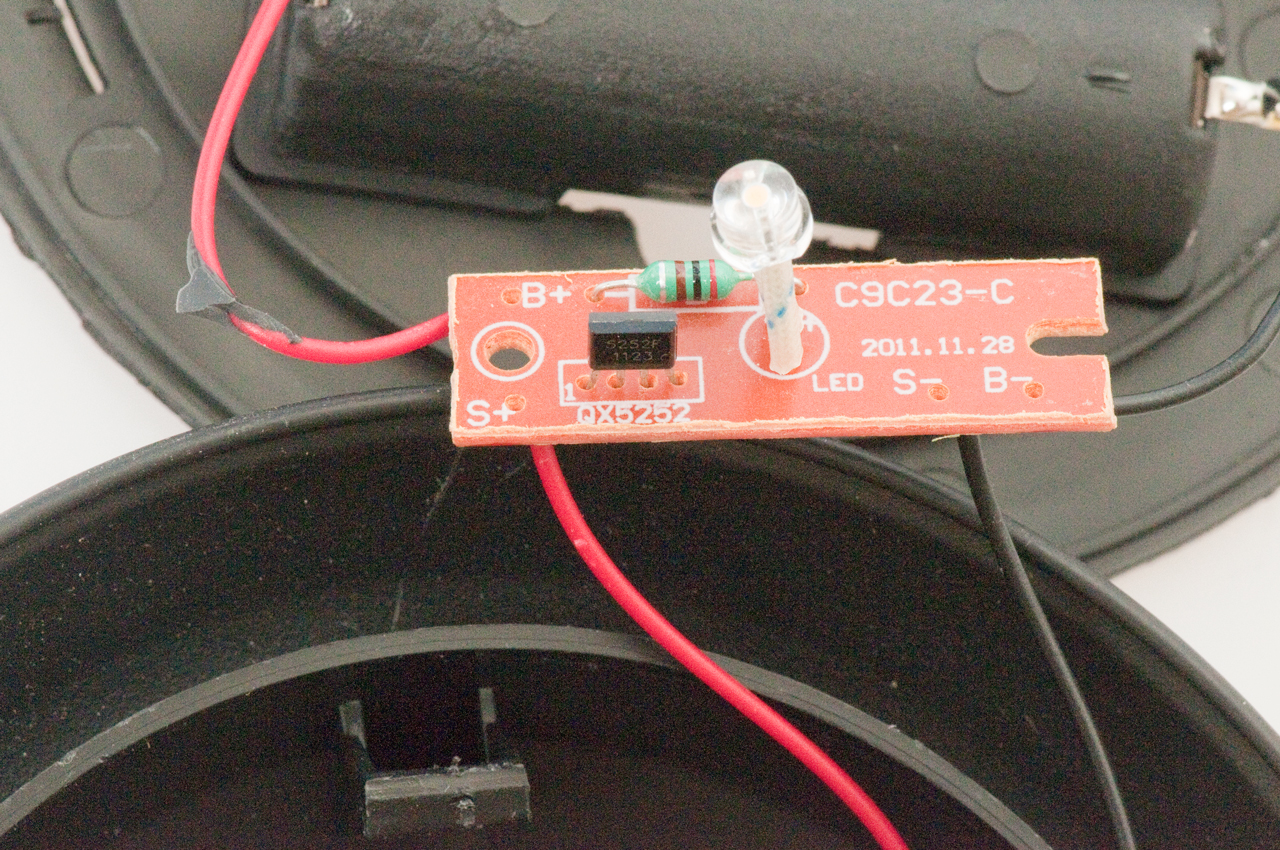
12 June 2013 - Got a Solar Path Light form Home Depot (bar code: 609839495522) for $2.88 and took it apart. It contained:AA battery rated at 250 mAh (tested 269 mAh)
QX5252E TO-94 (4 lead) IC
100 uH inductor (Red, Black, Brown, Gold = 200 uH 5%)
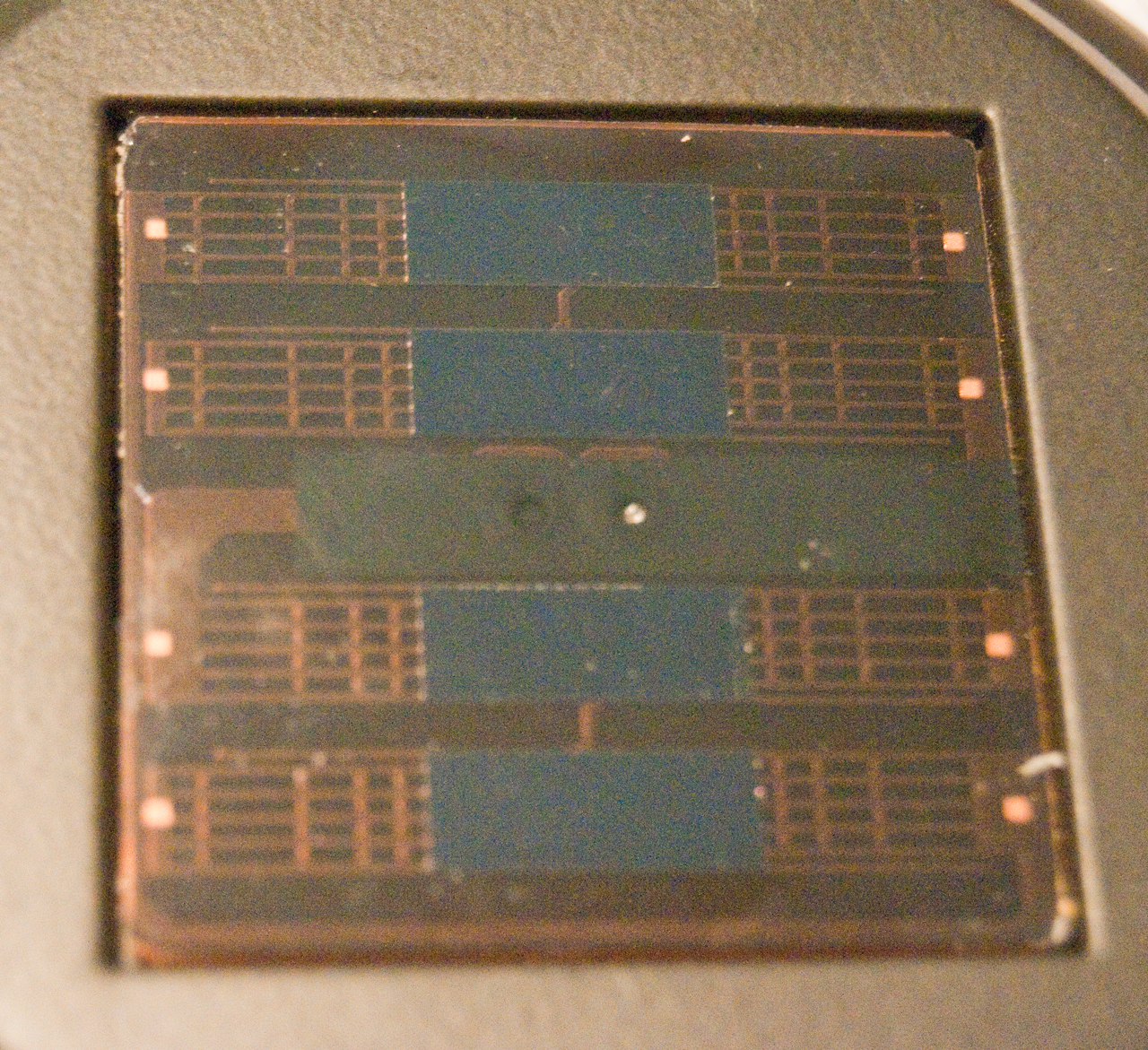
45 x 45 mm solar panel Open Circuit Output Voltage: 2.6
LED, warm white, with long leads (i.e. very weak if no heat sinking)
PCB about 1/4" x 1"
 |
 |
Solar Path Light
schematic with QX5252E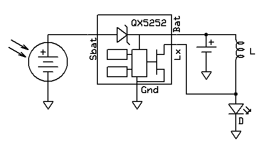 The QX5252F is in a different package and has an additional terminal for a CdS photo resistor to allow setting the turn off and turn on brightness. |
 |
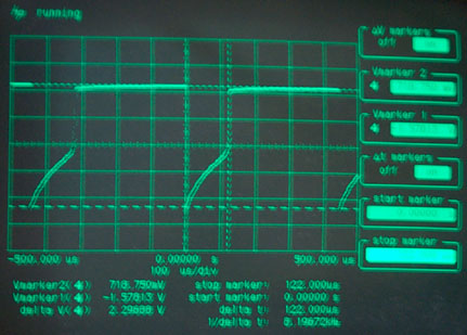
| QX5252 Waveform at Lx (between L and LED)
with LED On (Solar Panel in dark). From Rigol Scope - The Channel 1 yellow icon at left is at 0 Volts with a scale of 1 Volt/square. The negative going spike goes to - 480 mV The positive spike is at +4.12 V. Frequency 101 kHz The flat bottom is at 0 Volts (FET On - charging inductor) A little over 2 uS on time. 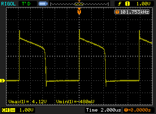 |
|
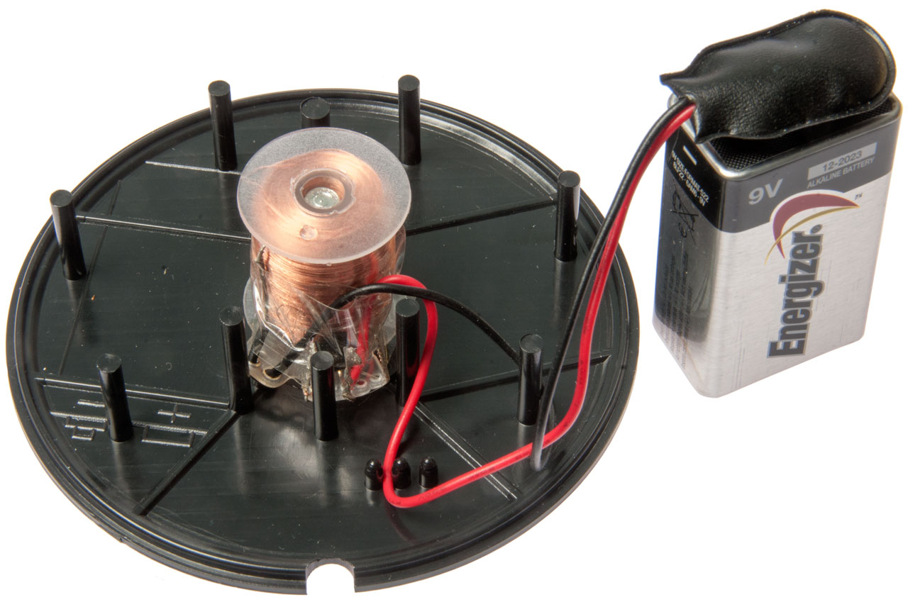
| Opened Rayovac and Energizer 9V battery
showing AAAA cells. Note the energizer has loose AAAA cells, but their polarity is backwards, i.e. point is negative. There's three jumpers in the energizer base each connecting 2 cells. The snaps on the Energizer are not on the center line, but are offset 0.5mm. A cleaver way to lower the cost, i.e. no Nickel tab & no welding. You also can remove individual cells. 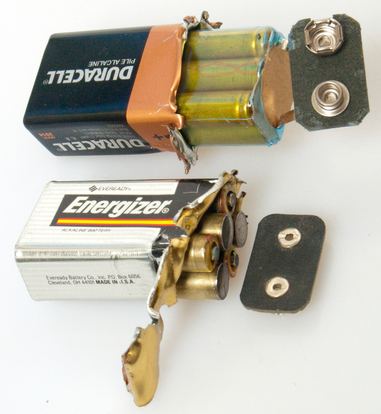 |
 If you look at the schematic you can see it matches the PCB. |
Walmart IDC IDC577105 (Westinghouse) Path Lights for less than $1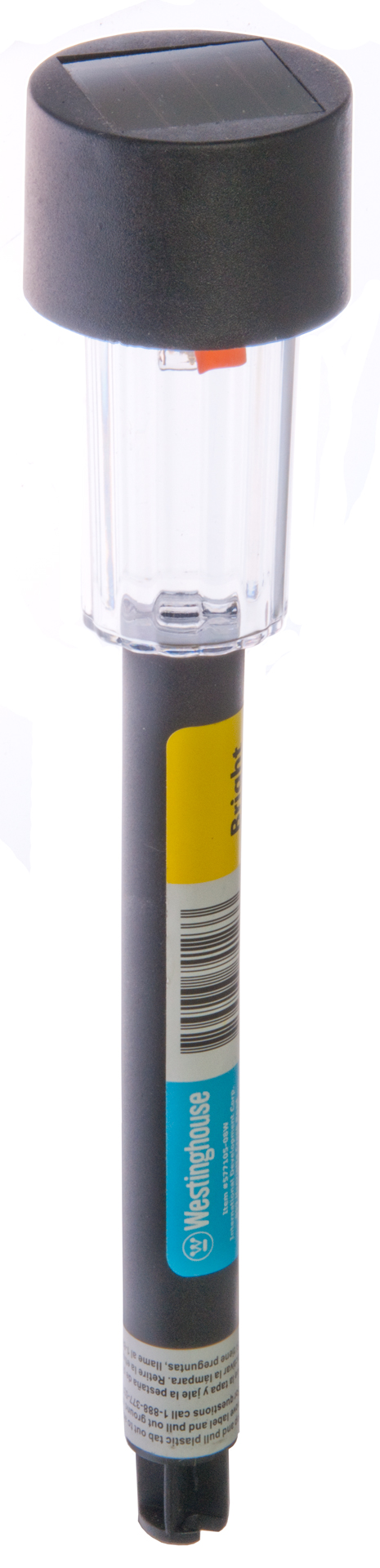 |
 The solar panel on this unit is 30mm x 30mm, smaller than the 45mm x 45mm panel op the Home Depot light. |
| This light has the QX5252E mounted as a
Chip On Board (Free
Dictionary) on the back of the PCB. The battery is a 2/3 AA size and is rated 150 mAh, the lowest capacity I've seen. I wonder how long and how bright this light is? 100 uH inductor. 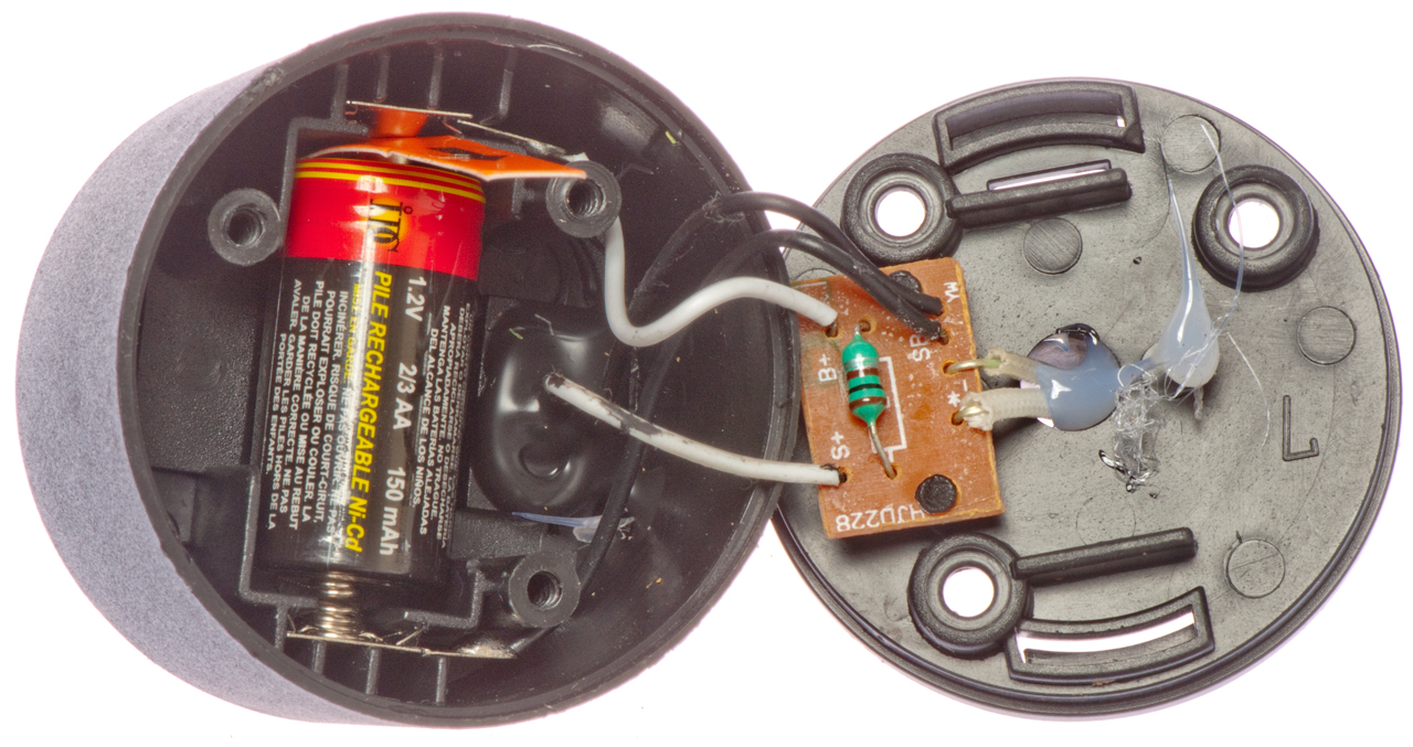 |
Comparing the Home Depot and Walmart solar
path lights The Home Depot on the left is a warmer light.  My tripod repair part has not arrived, expect it tomorrow. This is a hand held 2.5 second exposure @ ISO 1000 |
The mode of operation is not a classical Joule Thief, but rather an Induction Coil. (Wiki). The energy stored in an inductor is given by:
Energy equals one half the product of the inductance and the current squared. (Wiki)
When the Sun is shining the solar panel charges the battery because the voltage on the SBat terminal is higher than on the Bat terminal.
Note: the battery voltage is much less than the forward voltage of the LED so only a very small current flows through the LED and inductor during charging.
Note: the QX5252 terminal Lx is open during charging.
At night the voltage at the solar panel drops below the battery voltage enabling the light circuit.
The FET turns on shorting out the LED and connecting the battery and inductor in series, thus charging the inductor.
When the inductor is fully charged the voltage at the Bat terminal has dropped from about 1.4 V to zero at which point the FET turns off.
When the FET opens the inductor generates a voltage kick that's added to the battery voltage to turn on the LED for a very short time.
The voltage (with no load) is equal to the inductance times the rate of change of the current (Wiki).
After the inductor is out of energy no current flows through the inductor or LED. If it's still dark the cycle starts over.
This Solar Path Light retailed for $2.88 at Home Depot meaning that it is a very low cost product. This circuit is lower in cost than one that uses a two winding transformer like the classical Joule Thief. Another way they get the cost low is using a way undersized battery, i.e. 250 mAh.
I'm guessing that inside the AA case is really a AAAA battery (Wiki), see the photo above of opened Rayovac and Energizer 9V batteries showing the 6 AAAA cells inside.
| Battery |
Size |
Capacity mAh |
Chemistry | Weight Oz |
| Solar 250 mAh |
AA |
269 |
Ni-Cad |
0.5 |
| Energizer E91 |
AA |
3100 |
Alkaline |
0.8 |
| Imedion |
AA |
2100 |
Ready to Use Ni-MH |
1.0 |
| Energizer 522 |
AAAA |
600 |
Alkaline |
0.2 |
Wiki lists the capacity of the AAAA Ni-MH as 325 to 500 mAh so the "Solar" brand battery has low capacity even for a AAAA size, i.e. it's very cheap.
I upgraded my Solar Path Light by installing the Imedion Ready To Use battery which should increase the "hours of operation" from the sticker value of 1 hour to at least 8 hours.
Model LZ3W/LZ6W
 |
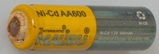 An Intermatic (Malibu) 600 mAh Ni-Cad that's totally dead. |
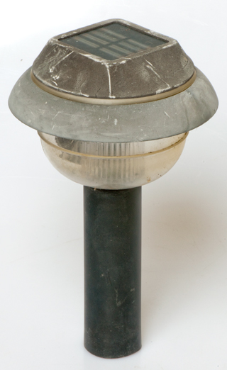
This unit is still functional, both battery
and electronics, but the top black plastic is turning to dust. 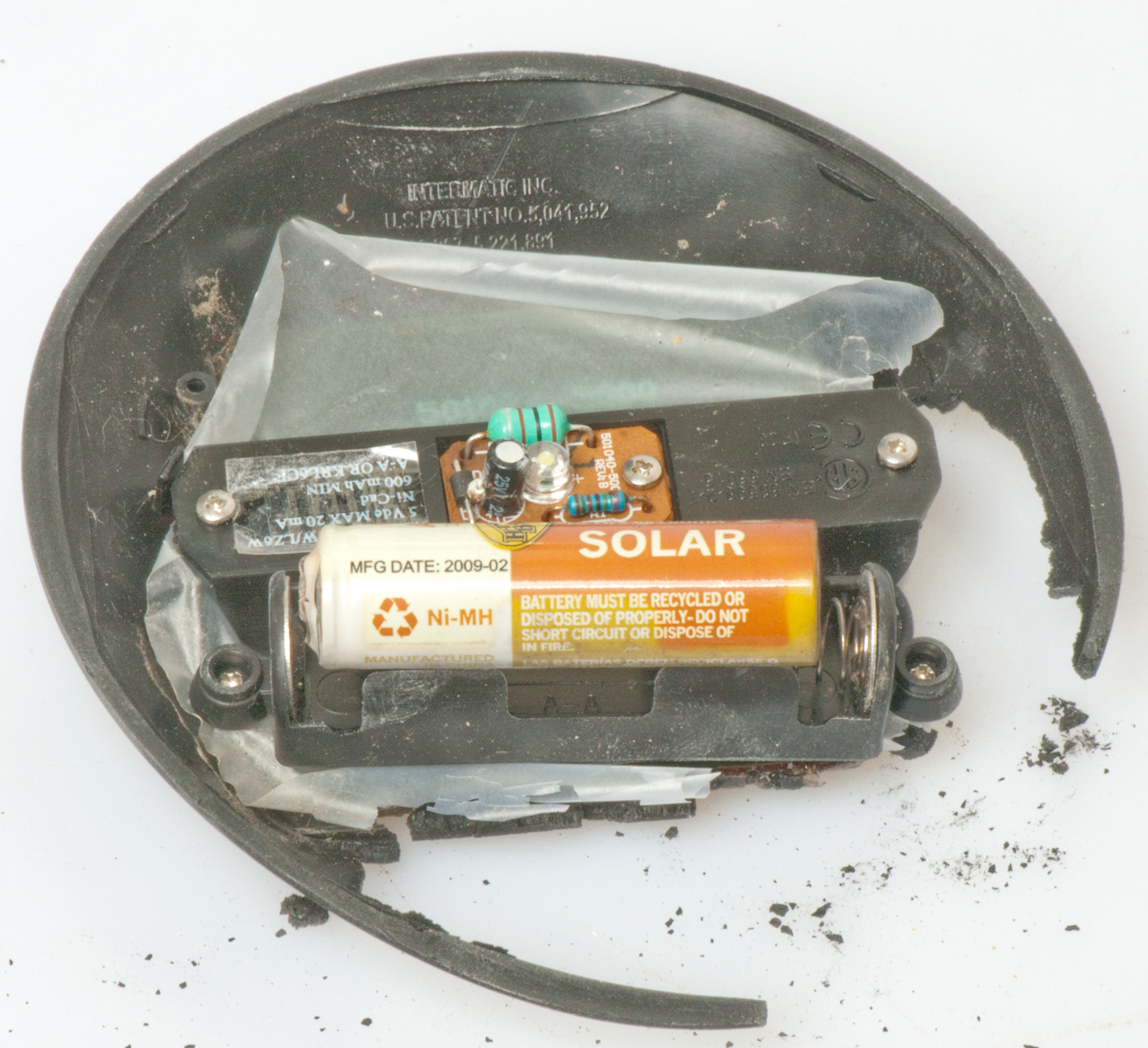 |
Old Unit with Discrete Parts Top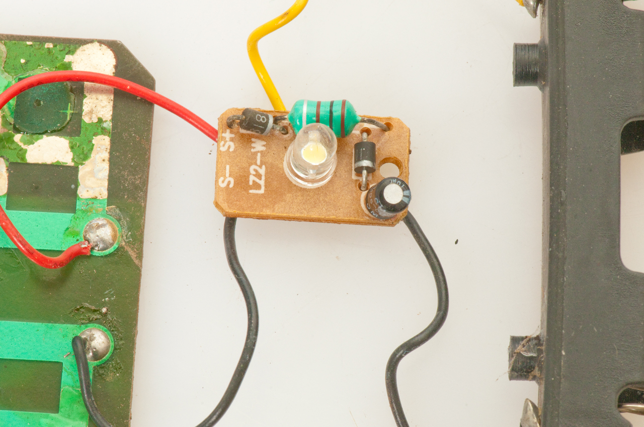 |
Old Unit with Discrete Parts Bottom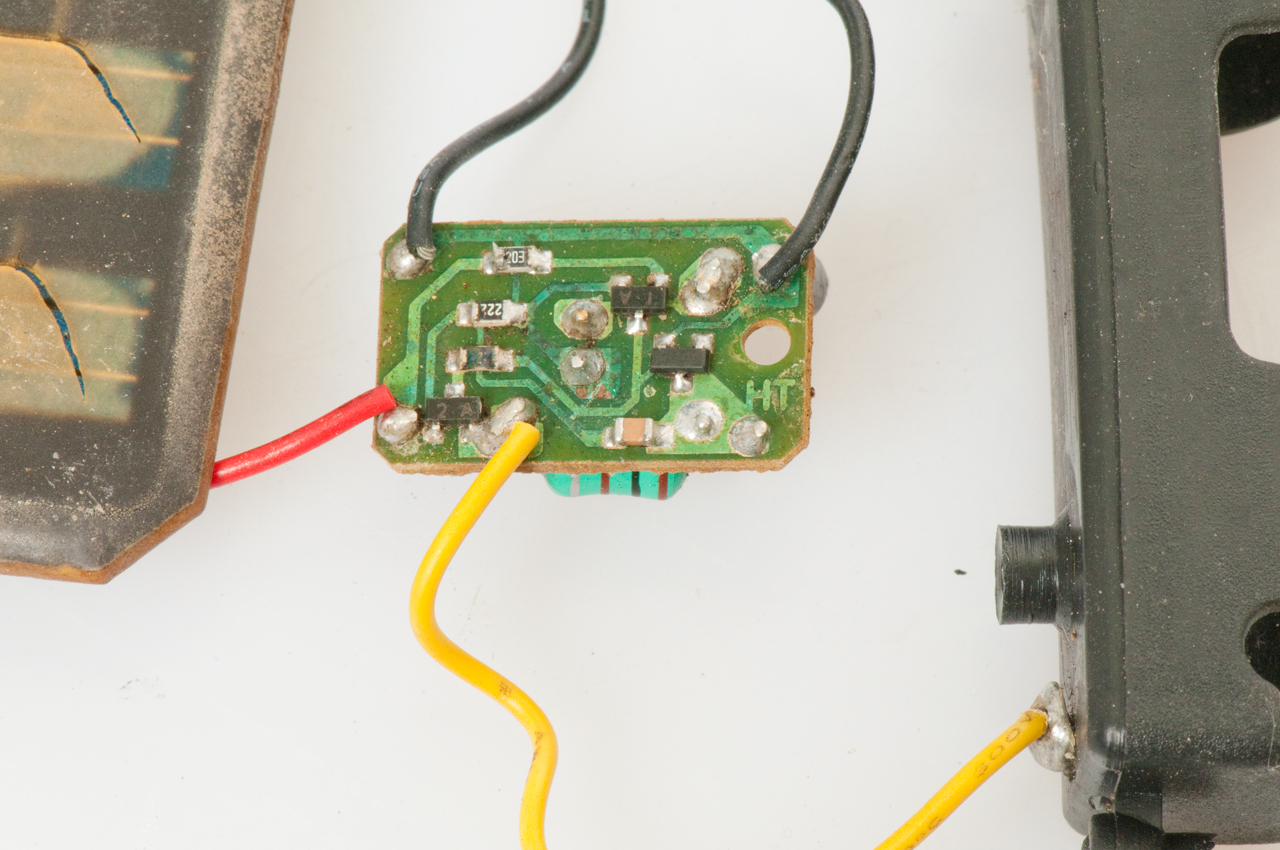 This may be the circuit in one of the old patents. |
23 July 2013- 7 out of 7 of these that were not working after installing a new battery were fixed by using a small file to clean the positive battery contact and the positive end of the battery, then putting a small dab of Silicon grease on the positive end of the battery. The idea is that the Silicon grease will keep out the battery fumes that are making a very poor connection. To test this just put a small screwdriver blade between the battery positive end and the light battery contact with the solar panel down and shielded from light. If the LED lights then that's the problem. |
These have battery date codes of 2009 (it's June 2013) and are
either dead or nearly dead.
To open place a knife blade gently between the black top and
the narrow clear plastic ring and gently pry. If it does
now separate a little move a little and try again. After a
few tries you will be able to remove the top without any new
damage (the Sun has already done a lot of damage).
Remove the old battery and install a fresh high capacity Ni-MH
cell.
The removed batteries were:
Malibu 600 mAh Ni-Cad (65 each)
Solar 1500 mAh Ni-MH - still working
Hampton Bay 800 mAh Ni-Cad - still working
6 of 8 batteries dead - all Malibu 600 mAh
6 of 8 of the electronics units still light the LED when the
solar cell is face down on a table (in the dark) and 1.3 VDC is
applied to the battery terminals.
1 electronics still works even thought the surrounding black
material has crumpled into dust. It may be transplanted
into a mechanically good but electrically dead unit.
Need to check the solar cells as a couple of them look like they
may be dead.
5086267
5221891
The IC is a Chip On Board so it's not at all clear how the circuit works, but it does have a 2 lead axial inductor like the unit above.
History
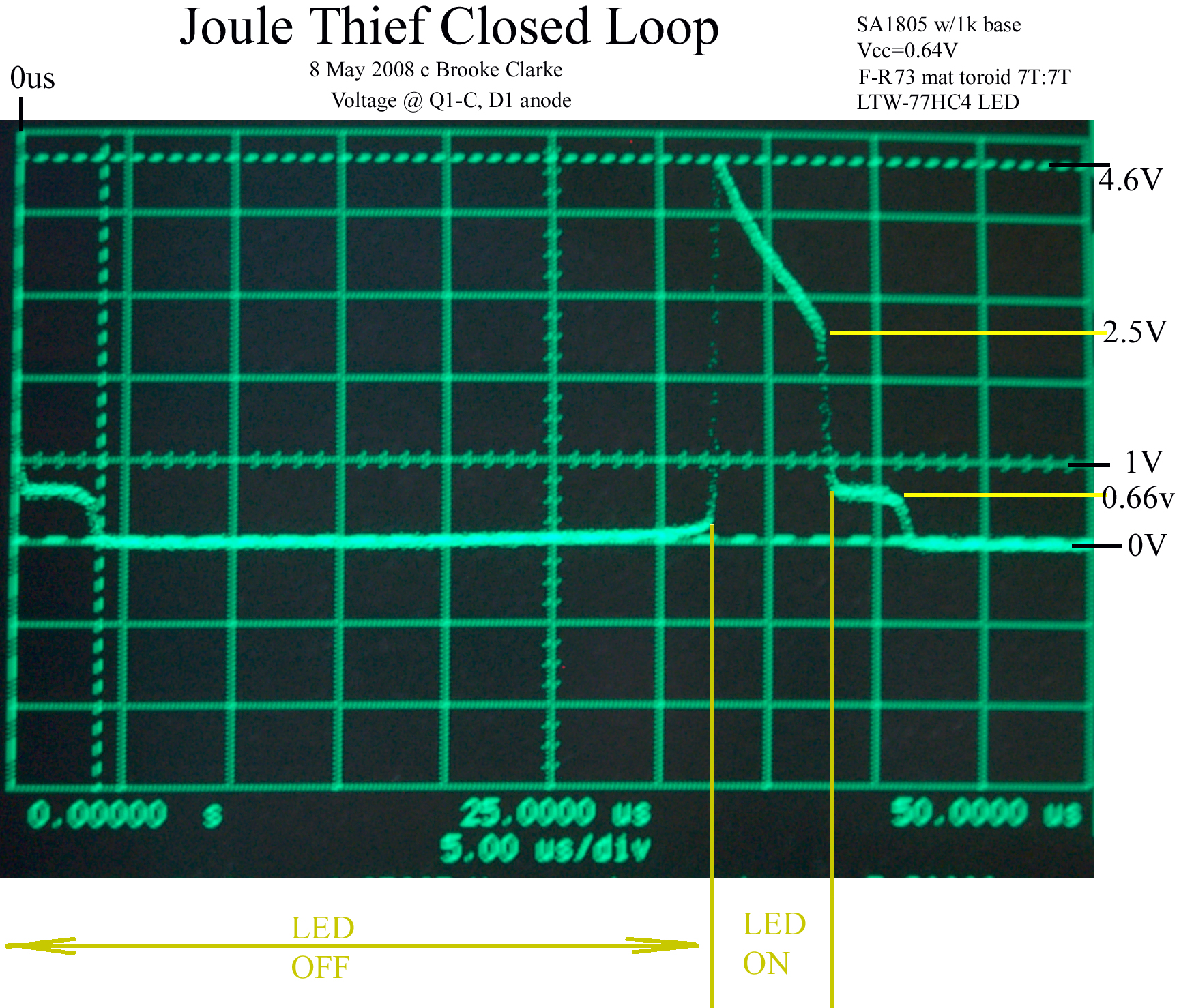
I started looking into a Blocking Oscillator as one way to power a High Brightness LED from a single cell battery (Alkaline, Ni-MH or a No. 6 Dry Cell). The early work is on the LED web page. But it's getting more involved so am starting a new page.Blocking Oscillators are also used in many other applications. For example if you remove the LED and replace it with a series connected high voltage diode and capacitor and add a third winding with many turns you can generate high DC voltages like used for flash cameras. With the 7 turn coil unit if the LED is removed the T1B pulse is about 85 volts.
The blocking oscillator is also used in some sea mines to power a flux gate magnetometer. They can also be used to drive a piezo disk.
Single Use Cameras use a blocking oscillator to generate the flash High Voltage.
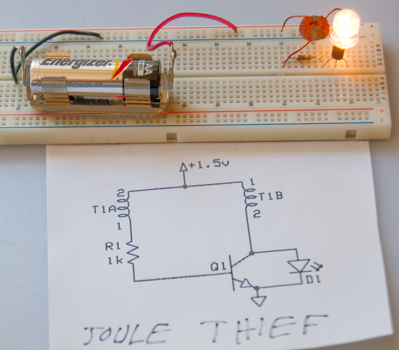
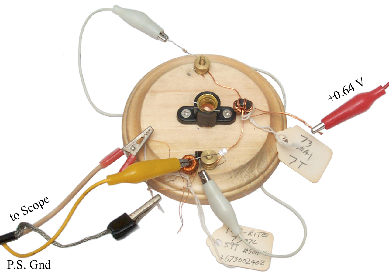
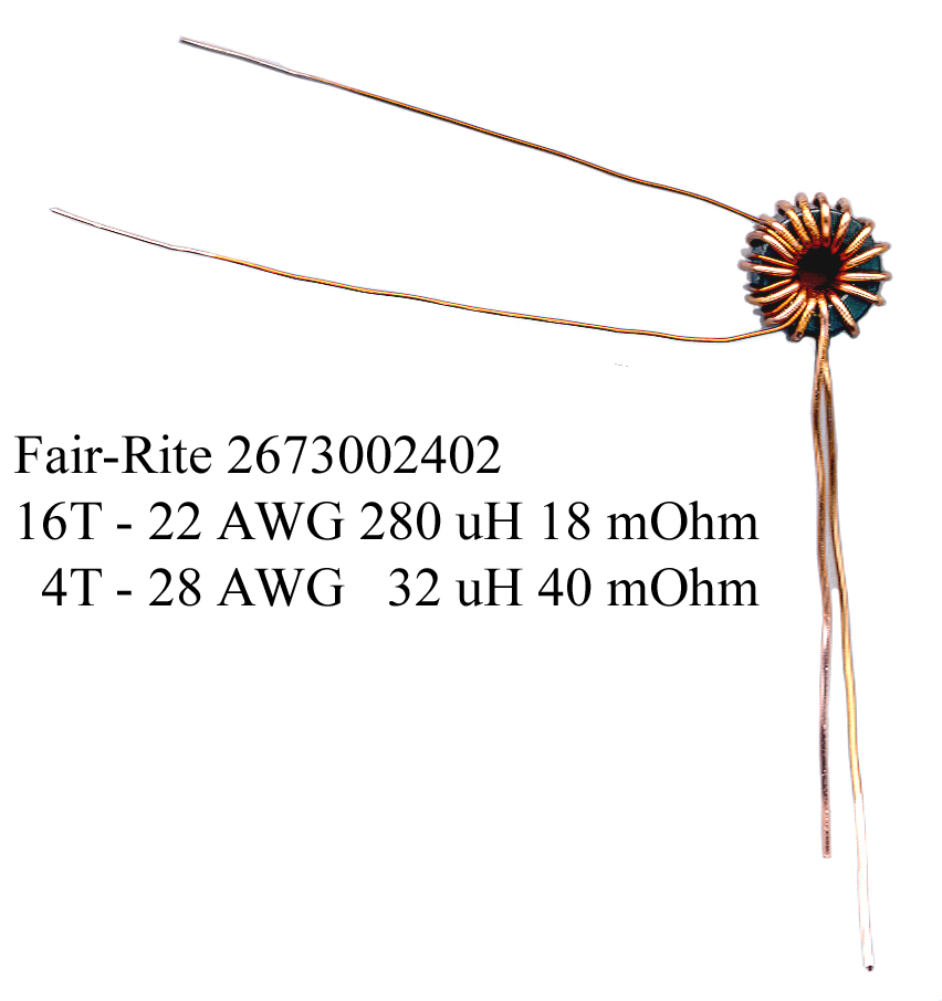
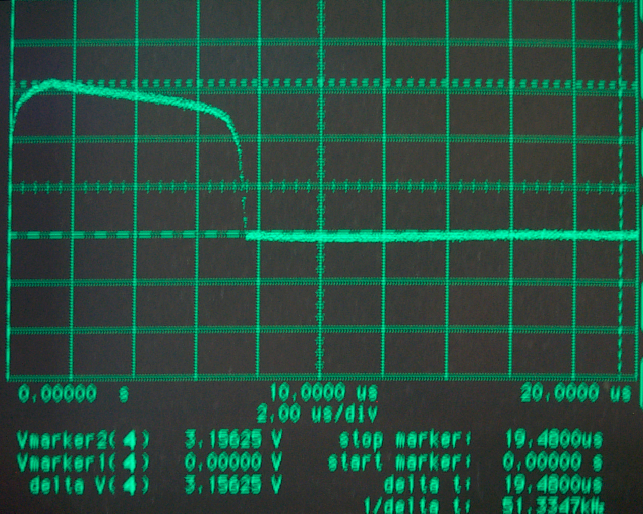
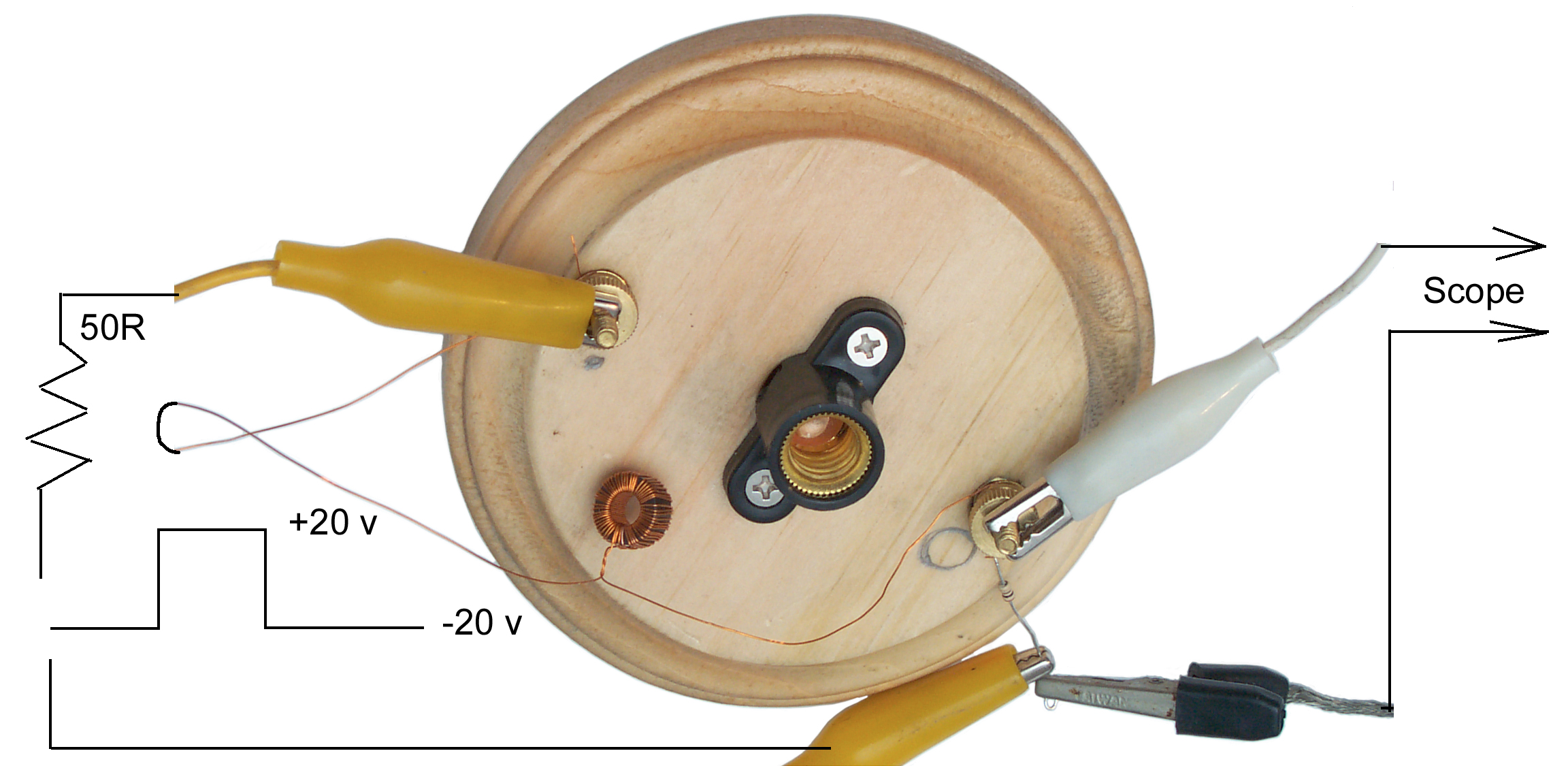
Working with the Fair-Rite toroid in 43 and 73 material everything seemed to work. The transformer is wound on a toroid of the same type as used to wind inductors.
But the 85 material (square B-H) did not. To investigate why a working unit using 73 material was measured again. I suspect that a different winding is needed with the 85 material. Here it is.