Quartz Kitchen Clock Movement
Sidereal Clock
© Brooke Clarke 2007 - 2019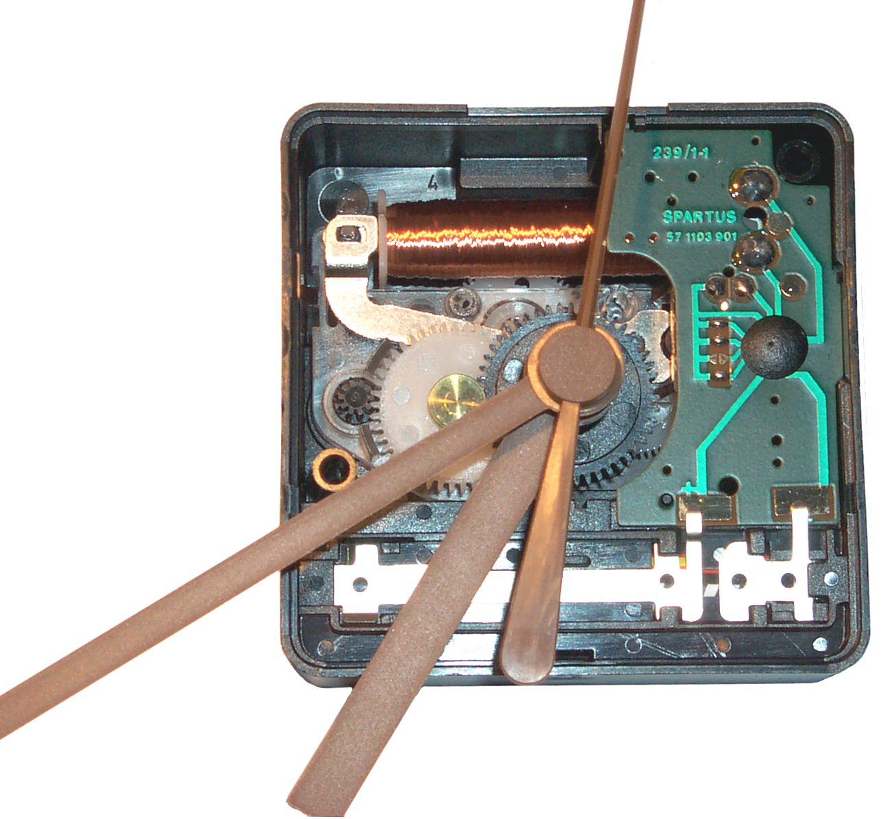
Background
Drive
Marking
Disassemble
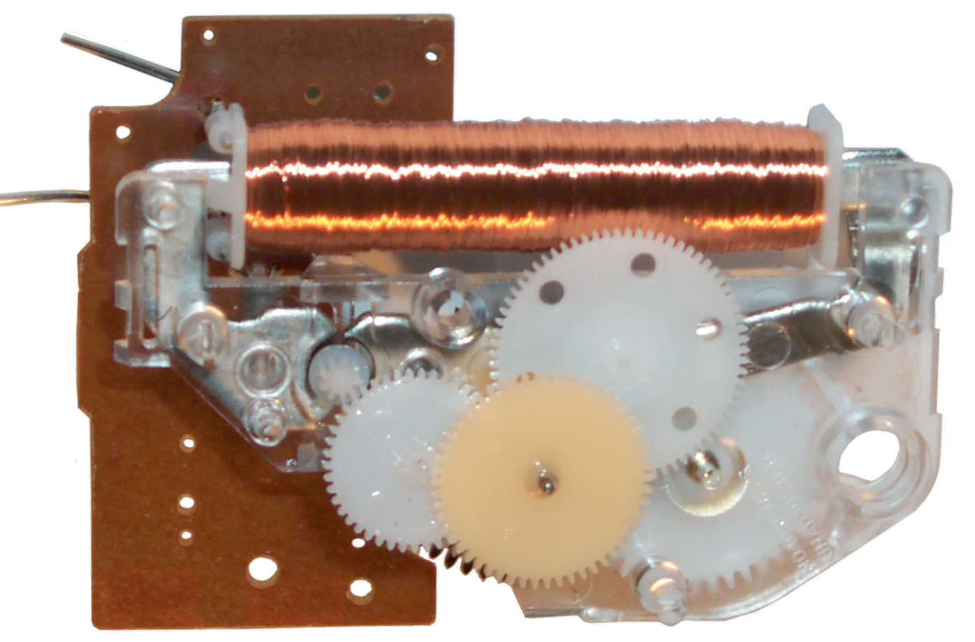 A number of plastic hooks hold the mechanism
into the movement box. All but one of these can be seen and
with a small screwdriver pried enough to lift the mechanism up a
little. But the one under the printed circuit board seemed
impossible to get to, so I cut a hole in the box. Here a
bottom view. Note that three gears and a flat spring dropped
off and have been reassembled for this photo.
A number of plastic hooks hold the mechanism
into the movement box. All but one of these can be seen and
with a small screwdriver pried enough to lift the mechanism up a
little. But the one under the printed circuit board seemed
impossible to get to, so I cut a hole in the box. Here a
bottom view. Note that three gears and a flat spring dropped
off and have been reassembled for this photo.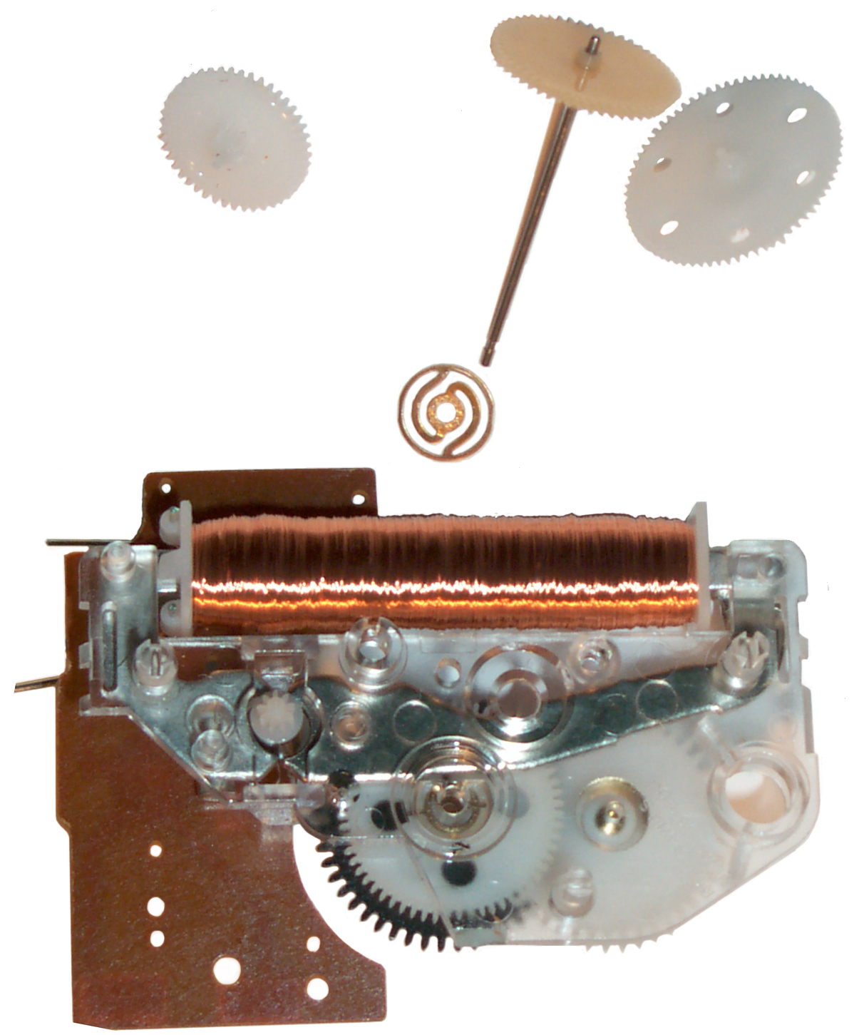
Patents
Also see the patents for tuning fork drives where maybe the earliest Poul La Cour (Wiki) stepping motor, Joule Thief Flip Flap Solar for more electromagnetic pendulum patents.Also see the Kundo electromagnetic pendulum clock.
788762 Electromagnetic device, Albert Favarger, May 2, 1905, 310/163 - bipolar DC drive rotates clock hand
1405502 Electric motor, Dodds Lee L, Feb 7, 1922, 310/49.47 - intended for slave clocks, but is a bipolar DC drive using 4 coils.
1603646 Electrical transmission system, Jr Elmer A Sperry, Sperry Gyroscope Co Ltd, Oct 19, 1926, 318/695, 188/171, 377/89, 310/93, 340/319, 310/127, 310/406, 310/216.92 - up to 20 steps per revolution, works after power failure
2036917 Electric timepiece, Philippe Favre-Bulle Maurice, Apr 7, 1936, 368/47, 968/482, 310/21, 310/25 - a vibrating reed (half a tuning fork) drives ratchet (Wiki) gear wheel, This is very similar to the Winding Mechanism of a Self Winding Clock Company clock.
2183062 Alternating-current direct-current clock, Conrad Frank, Dec 12, 1939, 368/169 310/36 310/163 318/129 318/132 318/134 368/200 968/523 - the hairspring is designed to do a poor job of regulating the speed of the balance wheel. That way the rectified AC locks the balance wheel. A battery keeps it going when the AC power fails.
A modification of the dry battery clock 1911062 Electric clock, Conrad Frank, 1933-05-23, - a spring loaded balance wheel is driven by a couple of electromagnets instead of an escapement.2415022 Motor device,Morrison Montford , 1947-01-28 -
GM used a similar mechanism for car clocks that run from the battery: 2741083 Electric clock ratchet drive, Raymond H Sullivan, Peter R Contant, GM, 1956-04-10
also see GM clocks: 2631423 2642714, 2711501, 2741083, 2768495, 2800799
2534155 Clock Timer, Harley C Wintle, GE, 1950-12-12, - a Clock Radio where the clock rate is determined by a tube type oscillator using the clock motor inductance as part of the resonant circuit.
2499316 Magnetic motor for visual indicator units, Johnson Ernest W, Transducer Corp, Feb 28, 1950, 377/82, 318/696, 340/317, 377/89, 235/61.0PK, 310/49.31 - includes a spring to return to starting position
2659853 Electric impulse motor device, Montford Morrison, Nov 17, 1953, 318/491, 318/443, 318/499, 968/550, 318/558, 310/49.22 - single direction stepping
2457637 ELECTRICAL MOTOR, Harrison D. Brailsford, Dec 28 1948, 310/46 ; 310/40MM; 310/40R - self starting (offset magnetics) pulsing clock drive motor, very low power
Fig 4 shows the structure2719944 Commutatorless direct current motor, Harrison D Brailsford, 1955-10-04, - transistor commutator
References:
362322 ELECTRIC MOTOR, EOBEET J. SHBBHY, May 3, 1887, 310/46 - 4 coil looks like start stop stock ticker drive
1367982 MOTOR, QTTSTAVE Lidseen, Feb 8, 1921, - AC/DC armature has teeth instead of windings
2185990 INDUCTION MOTOR, self starting
2214850 SELF-STARTING SYNCHRONOUS MOTOR, GE 1939 - uses permanent magnet for rotor
References:
1497394 Alternating Current Motor, Henry E. Warren (Warren Clock Co), Jun 10 1924, 310/163 ; 310/126 - self starting AC synchronous
3076944 Frequency transforming circuits utilizing negative resistance, Robert L Watters, GE, 1963-02-05, - Tunnel Diode divide by N.
3081436 Negative resistance diode oscillator, Robert L Watters, GE, 1963-03-12, - 18 MHz Tunnel Diode oscillator
3168690 Clock power-device, Marius Jean Lavet, Jacques Jean Gustave Dietsch, Leon Hatot SA, App: 1954-08-31, Pub: 1965-02-02, - transistor commutator
3292064 Frequency regulated chronometer, Robert L Watters, GE, 1966-12-13, - 105.84 kHz transistor oscillator divided by 6 then 7 then 7 (ie. 105.84 kHz / 294 =360 Hz). for use with the Bulova accutron tuning fork movement.
3539845 Motor whose magnetic circuit comprises a thin layer of hard magnetic material,Georges Stcherbatcheff, RECH EN MATIERE DE MICRO MOTEU, 1970-11-10
3731125 Pulse motor for time piece,A Nikaido, M Onda, F Nakajima, T Machida, T Toida., Y Yanagawa' Citizen Holdings Co Ltd, 1973-05-013818690 Stepping motor for watch movement, G Schwarzschild, Timex Corp , 1974-06-25
3878414 Electric motor arrangement, Mototaka Harakawa,Star Micronics Co Ltd, 1975-04-15 -
3958167 Pulse motor,Fumio Nakajima, Akira Nikaido, Mitsuo Onda, Takayasu Machida, Takashi Toida, Citizen Holdings Co Ltd,
3969642 Step motor for electronic timepiece
4066947 Stepping motor for electronic timepiece,Fumio Nakajima, Takayasu Machida, Kenji Yamada, Citizen Holdings Co Ltd,
4550279 Step-by-step motor unit, Eric Klein, FABRIQUES D'EBAUCHES, 1985-10-29,
In 2014 there was some interest in "Crazy Clocks" where the time would stop and then run fast. To make these a small printed circuit board was put on the market with a number of different versions of the Crazy Clock and one of those versions was for a clock that tells sidereal time (Wiki).
To be useful a sidereal clock needs to tell Local Mean Sidereal Time not some universal sidereal time, i.e. to take into account your longitude offset from the center of your time zone. That way if you know the Right Ascension (Wiki) of a star that's the sidereal time when the star crosses your local North - South meridian.
To make this clock I started with a "10" Zulu Time 24 Hour Wall Clock" from eBay seller pilotmallaviationsuperstore and a "Crazy Clock" PCB with the Sidereal option.
It is now at the Ukiah Latitude Observatory.
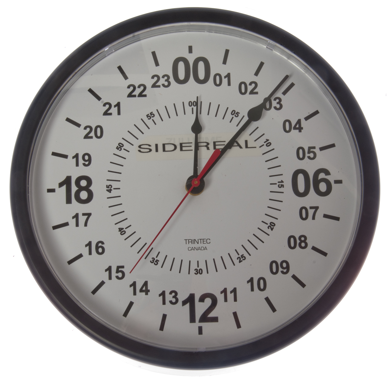
Fig 1 Remove the clear plastic clock bezel by pressing the 3
fingers on the back in and out using a screw driver and remove.
Note the hands are all at midnight.
Pull off the second hand.
Remove the nut and minute hand.
Pull off the hour hand.
Remove the nut and washer and remove the Quartex 24h movement.
The instructions on how to open the Quartex are on the Crazy Clock web page.
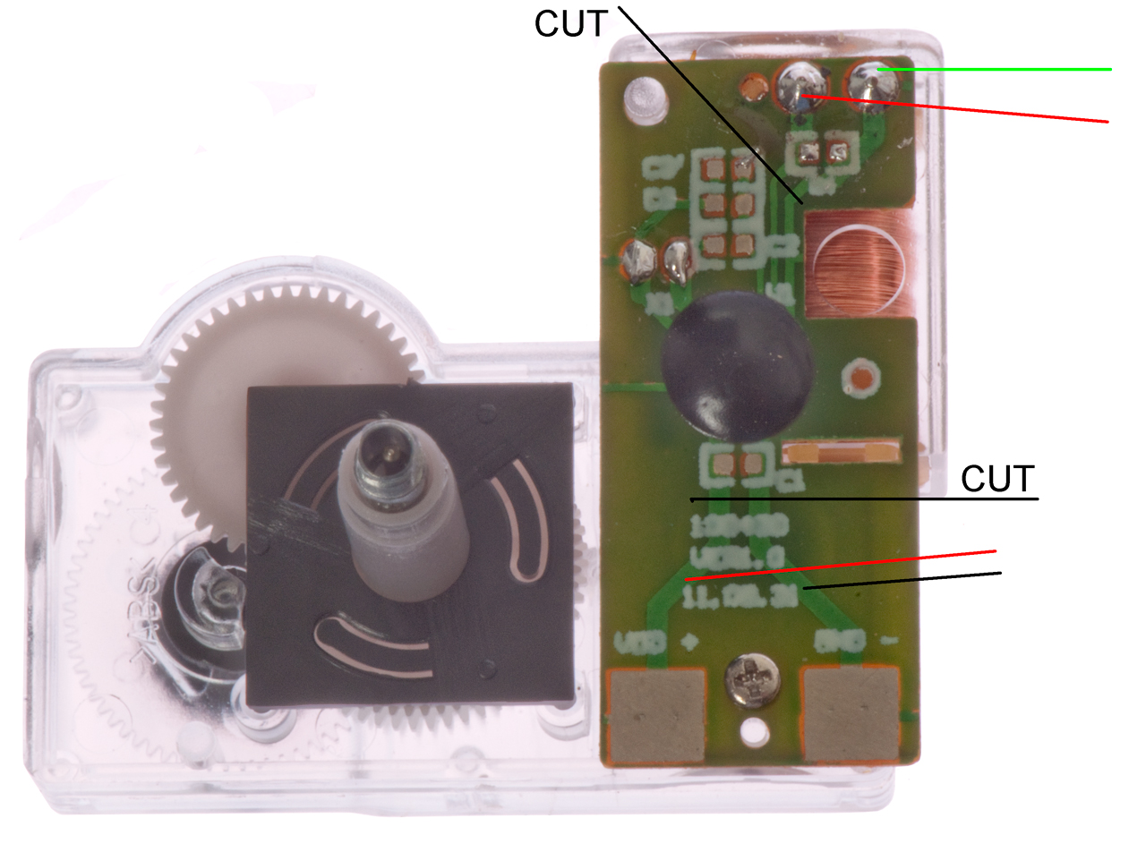
Cut the two battery traces and the two motor traces as
shown below and solder wires as shown below.
Cut notches in the plastic cover to clear the wires.
Place "SIDEREAL" label over Zulu Time.
Solder red wire to Batt+ and black wire to Batt-.
I don't think it matters which motor wire goes to which terminal.
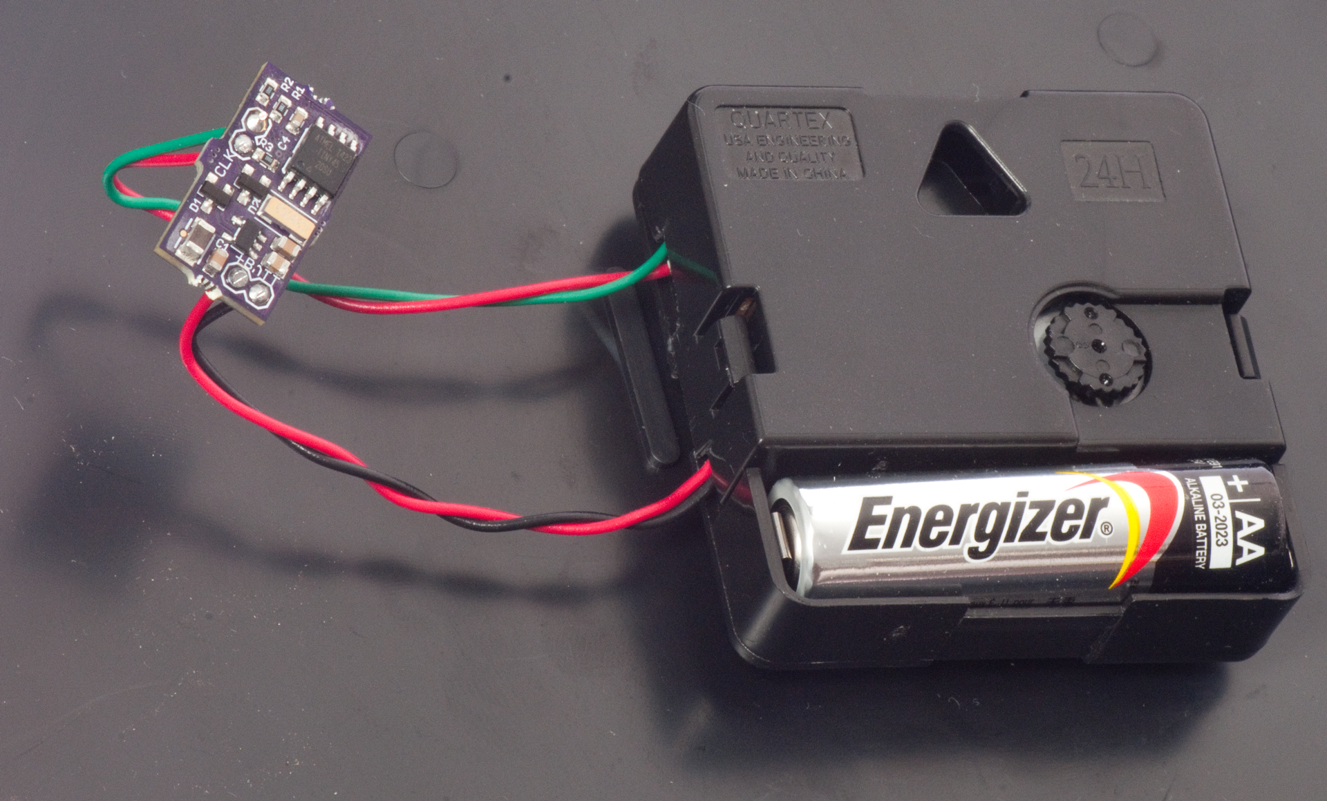
Fig 2 Crazy Clock board installed in clock.
Fig 3
To set the clock you can use the USNO LST web page: Compute Local Apparent Sidereal Time or an app on your cell phone for LMST.
PS. Since the clock comes with all three hands pointing to midnight, it makes it much easier to start up the clock at midnight LST or shortly thereafter. That way you do not need to rotate the time setting dial a million turns.