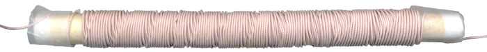
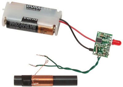
WWVB Loopstick Antenna & C-Max Receiver
© Brooke Clarke, 2003 -
2022 2.5" rod 2.5" rod |
|
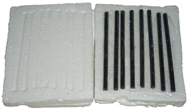
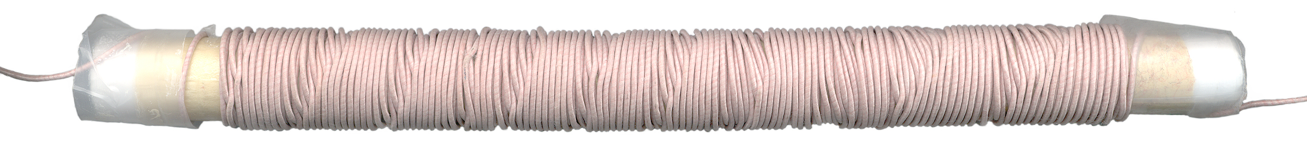
Bank Winding
The following explanation of "Bank Winding" is for a 4 layer coil.
"Bank Wound" means that you start the winding at the left end, then make 4 turns then wind backwards for 3 turns then forward for 2 turns and then backward for one turn. Now there are 4 layers of wire all at the left end. This process is repeated until the length of the rod is covered. The important fact about this type of winding is that the electrical distance from any one turn to it's immediate neighboring turn is is just a few turns. If the coil was wound a layer at a time, then the electrical distance between turns may be hundreds of turns. The self capacity of the completed coil depends on both the capacity between adjacent turns and also the voltage between the turns.
If you look at the equivalent circuit for a single layer coil where the turns are spaced about one wire diameter it can easily be seen the the total coil voltage is divided so that 1/N of the voltage is across each turn-to-turn capacitance. That's to say the capactance is very closd to the capactance of the first to the last turn. But if you added a second layer then the two coil terminals are at the same end and the turn-to-turn capacitance for the turns adjacent to the two terminals has 100% of the coil voltage across it. The next turns away from the terminals has (N-1)/N of the full coil voltage, etc. This results in a huge self capacity.
Litz Wire
There are a number of effects that cause the A.C. resistance of a wire to be higher than the D.C. resistance.
Litzenhardt wire is made up of a number of independent conductors that are insulated from each other. There are a large number ways that the strands can be arranged.Skin Effect
In a straight wire, with no other wires near by, as the frequency increases the electrons carrying the current move away from each other and so end up more and more near the surface of the wire and less and less along the centerline.
Proximity Effect
Is similar to Skin Effect, but is caused by the interaction between wires that are near to each other.
The wire I used is made from AWG number 44 wires that are in bundles of 36 wires and there are 5 of these bundles in the final wire. If you needed a cable with 180 seperate wires you could use this Litz wire that way. Since a single # 44 wire has a diameter of 0.00198" the total area of the 180 wires is equivalent to a solid wire of diameter 0.02656", or between AWG 21 and 22.
The correct term may be Litzendraht, meaning Litzen (braided) Draht (wire)
Thanks to John Portune W6NBC
The problem is the insulation takes up space that could be used for copper. The result is that Litz wire typically only works well below a few MHz. It's interesting that at mains power frequencies (20, 50 or 60 Hz) the largest size single strand wire you can buy is determined by skin effect. If a load requires more square mills of copper area then you need to use multiple insulated conductors.
MWS - Litz tool - input the AWG size to get the cross sectional area and it tells you the available strand count and wire sizes.
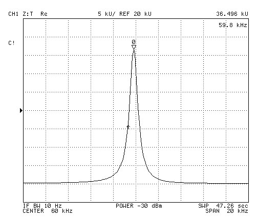
The following plots were made using the HP (Agilent) 4395A in the Network Analyzer mode and using the Z Transform technique where the unknown device is placed in series with the center conductor.
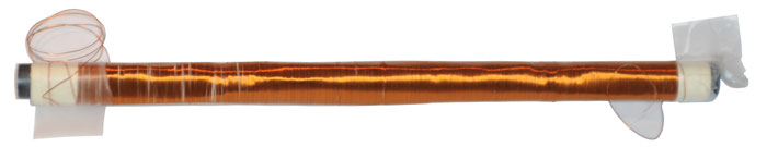
The problem with this winding is that it's very difficult to bring it to reasonance because of the difficulty in finding fixed caps of the exact value you need.
A much better approach is to make the coil on a sliding former so tuning can be done simply by sliding the former. That's the way the commercial WWVB antennas are made.
Imaginary Part of Impedance Plot
The marker shows 1.004 k Ohms at 32.960891 kHz. The network analyzer has already separated the real and imaginary parts so this is pure inductance.
L = X / (2 * PI * F) = 4.83 mHReal Part of Impedance Plot
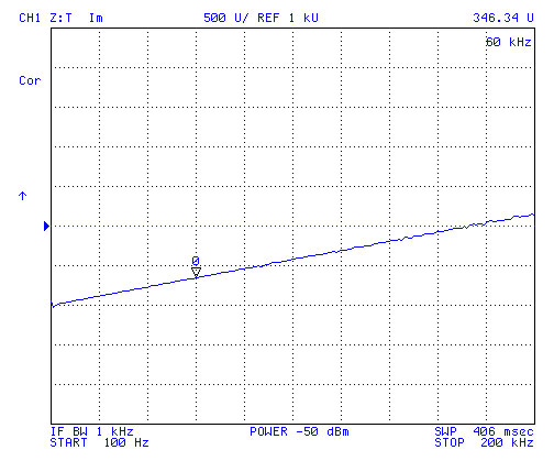
You can see that at 100 Hz the real part of the impedance is about 1 Ohm. i.e. the DC copper resistance. The marker shows the resistance has climbed to 29.325 Ohms at 60 kHz.
Without making a plot of "Q" vs. frequency and analyzing the slope it's hard to say what's causing the resistance. It may be skin effect, proximity effect, or dielectric losses or some combination of these.Resonated with Mica caps
Marker shows 94.308 dB at 62.485345 kHz.
Ohms = 10 ^ (dB/20) = 51, 927 Ohms.
The shunt capacitance is given by:
C = 1 / [ L * (2 * PI * F)^2] = 1.34 nF
The HP 4332 LCR meter measured the caps at 1.35 nF.
The loading capacitance value was chosen so that when the coil, caps and a small variable cap and the input capacitance of an amplifier are connected the resonance point can be brought right on 60.0 kHz.
The Q = XL / R = 51,927 / 32.96 = 1,575
A similar plot of just the coil shows that it's self resonance frequency is very close to 500 kHz. That's good in that you don't want to run a high Q coil near it's self resonant frequency and here we are well away from it.
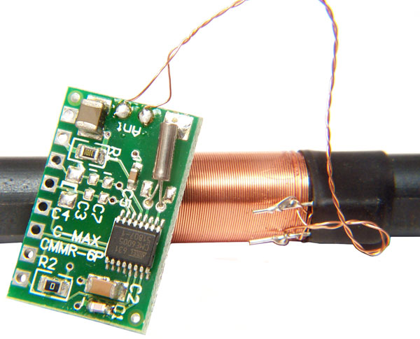 The CMMR-6P-60
is the 60 kHz version (they also offer 40 kHz and 77.5 kHz versions)
for WWVB. It's based on the C-MAX CME6005 which is the analog
front end without a CPU.
The CMMR-6P-60
is the 60 kHz version (they also offer 40 kHz and 77.5 kHz versions)
for WWVB. It's based on the C-MAX CME6005 which is the analog
front end without a CPU.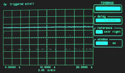 The gaps in the bottom part of the trace correspond
to the time code. But they are not solid.
The gaps in the bottom part of the trace correspond
to the time code. But they are not solid.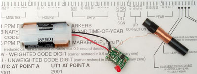
|
|
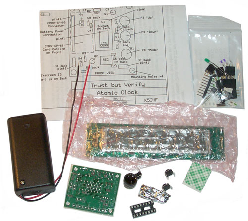
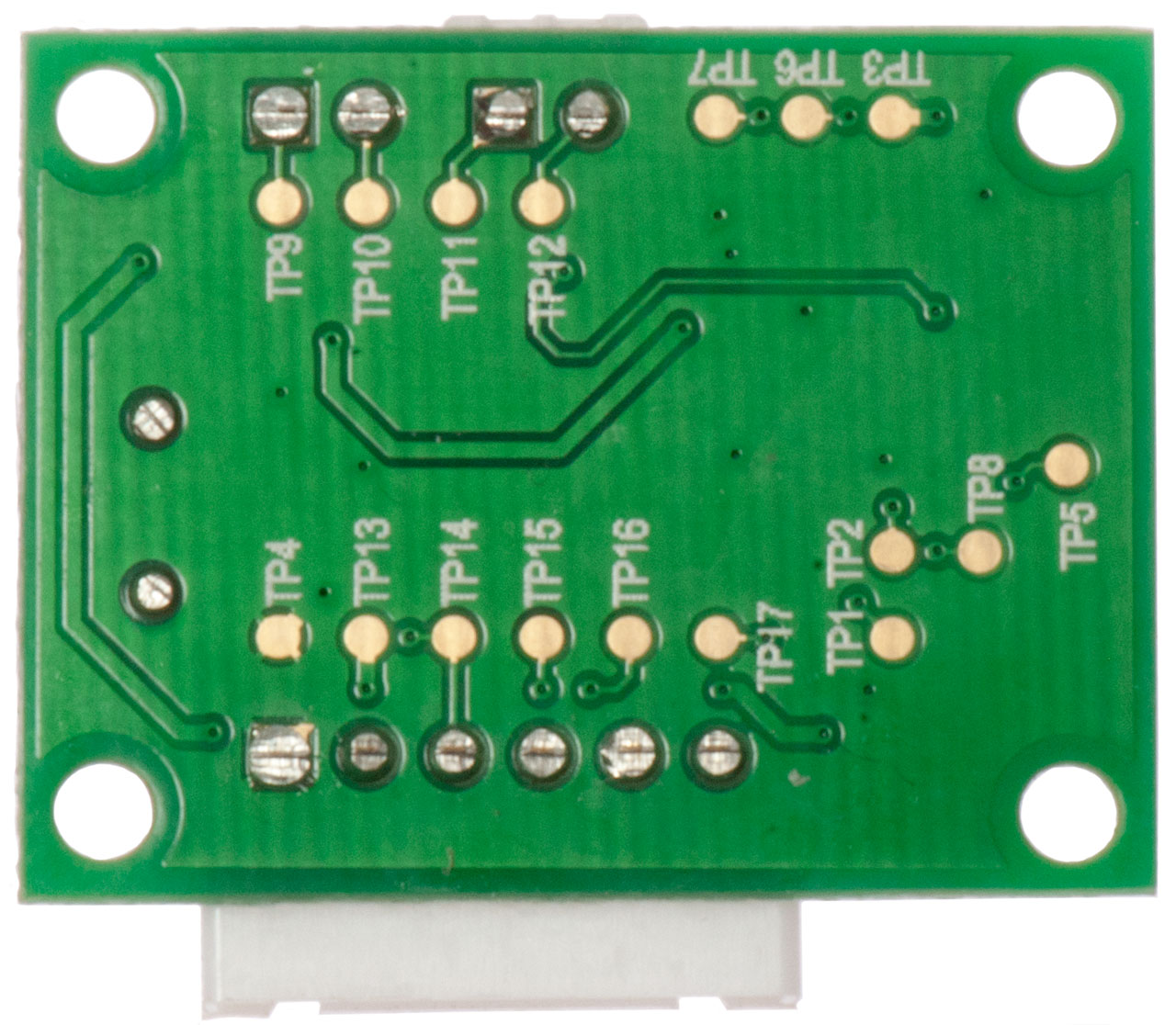
A couple of wires were
soldered to the board so that other antennas can be
connected.
|
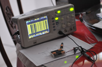 |
When the scope is close to
the receiver the data is corrupted. |
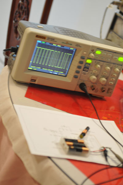 |
Moving the receiver away
from the scope solves the problem. Note: In a real application if the receiver is near electronic equipment there may be a similar problem. A Nikon D300s camera when close also corrupts the data, discovered when making the video below. |
 |
|
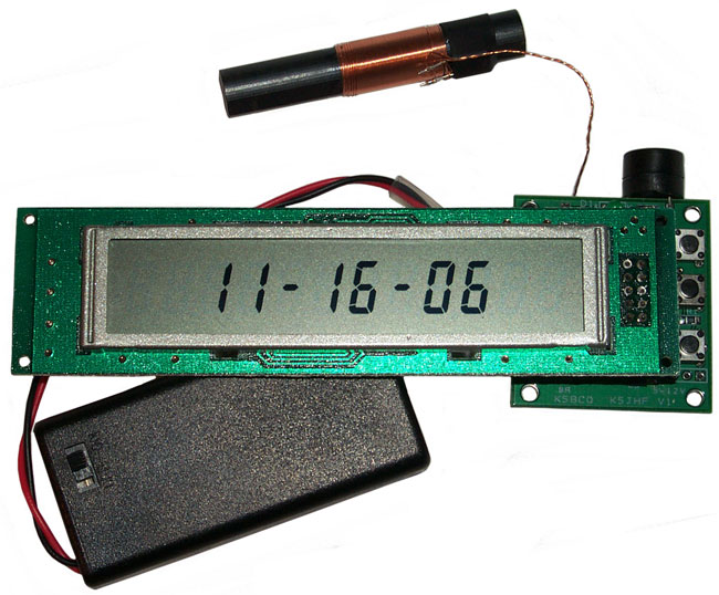
Kit Assembled Running Without
WWVB Receiver |
The clock comes up in hh-mm-ss mode and with CW ID active. The LED flashes along with the CW. |
| When
looked at |
yy mm dd hh mm ss |
| 19 Feb 2010 about 11:51 (Day
of Year = 50) UTC = 19:50 |
10 02 19 05 01 59 |
| 19 Feb 2010 about 12:01 | 10 02 19 05 01 59 |
| This
means that the clock lost lock at 5:02 am this morning, but
no first letter has appeared since so am confused how they
work. |
|
| 20 Feb 10 am |
10 02 20 01 01 59 |
| 23 Feb 9:32 am |
10 02 20 01 01 59 |
| This
menas the clock has NOT synced for a few days. The
time show is 12 seconds slow. |
|
 This
photo of the clock running a little before noon shows no prefix
letter. Note I have assembled the kit so that the setting
buttons are facing the same direction as the LCD face to make it
easy to operate the buttons.
This
photo of the clock running a little before noon shows no prefix
letter. Note I have assembled the kit so that the setting
buttons are facing the same direction as the LCD face to make it
easy to operate the buttons. | L |
Loss of detectable signal |
| U |
detected a signal
but has not detected a 200ms sync (Un Locked) |
| E |
received noise and is starting the sync detect again |
| S |
detected a 200ms Sync and needs a second sync before it sets the clock |
| <blank> |
two consecutive syncs detected and the clock is set/synced |
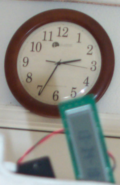 |
The WWVB wall clock is
displaying the correct time of 14:34:16, but . . . The K5JHF clock is displaying 13:34:19, i.e. there's a 1 hour error. The Heathkit GC-1000 WWV clock has a similar problem in that it makes the DST/STD time swtich when the station in Colorado changes, not in your time zone. The last sync word is: yy mm dd hh mm ss 10 03 14 05 03 59, so it was in sync early this morning and so the problem is a software bug, not a lack of sync. |
| Dist inch |
L mh |
Q |
| -0.147 | 25.58 | 150 |
| 0 | 25.62 | 160 |
| 0.25 | 25.37 | 160 |
| 0.5 | 24.74 | 150 |
| 0.75 | 23.74 | 160 |
| 1 | 22.58 | 150 |
| 1.25 | 21.29 | 150 |
| 1.5 | 20.01 | 150 |
| 1.75 | 18.66 | 150 |
| 2 | 17.31 | 150 |
| 2.25 | 15.75 | 50 |
| 2.5 | 14.45 | 50 |
| 2.75 | 13.12 | 50 |
| 3 | 11.87 | 50 |
| 3.25 | 10.62 | 60 |
| 3.5 | 9.42 | 60 |
| 3.75 | 8.25 | 60 |
| 4 | 7.17 | 60 |
| 4.25 | 6.15 | 60 |
| 4.5 | 5.2 | 60 |
| 4.75 | 4.3 | 50 |
| 5 | 3.556 | 49 |
| 5.25 | 2.841 | 43 |
| 5.5 | 2.231 | 35.5 |
| 5.75 | 1.686 | 28 |
| 6 | 1.2352 | 21.1 |
| 6.25 | 0.8902 | 15.5 |
| 6.5 | 0.6566 | 9.5 |
| 6.75 | 0.4852 | 8.6 |
| 7 | 0.4014 | 7.1 |
| 7.25 | 0.3667 | 6.5 |
| 7.5 | 0.3615 | 6.4 |
| 7.75 | 0.3609 | 6.4 |

|
HP 4274A LCR Meter
measuring 160 turn Loop antenna.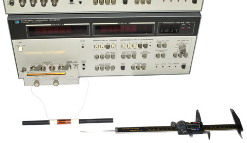 |
Loop 120T close spaced
Imaginary no cap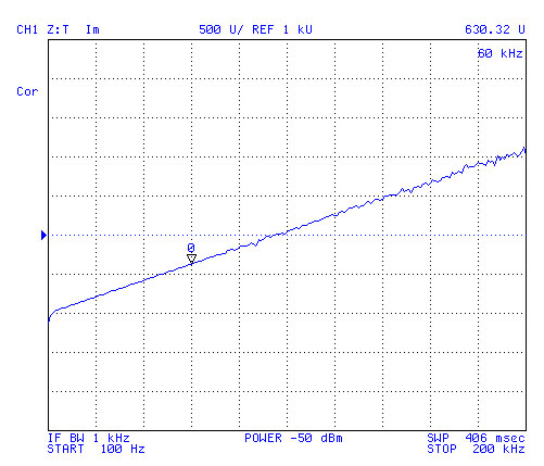 |
Something may be wrong
with this plot |
WWVB Loop 120T on Russian
Ferrite Real-Z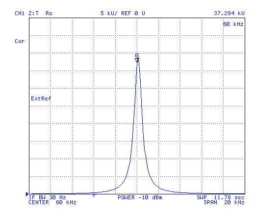 |
A 4n7 cap has an
impedance of 564 Ohms at 60 kHz. If the real
resistance of the tank at 60 kHz is 37.3 k Ohms then the
Q is 66 which is about half the Q from the 4274A LCR
meter at 40 kHz. |
WWVB Loop 160T on Russian
Ferrite Imaginary-Z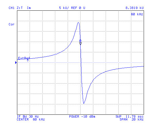 |
|
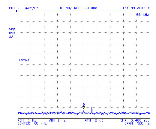 |
1 Hz RBW Noise is about -146 dBm detection method is sample (i.e I&Q true noise, not peak detection) Tank circuit connected directly to 50 Ohm input. When a Galleon 60 x 10 mm 60 kHz resonant loop-stick was connected to the exact same setup, after 32 averages there is no signal at 60 kHz so the 200x10 mm Russian ferrites make better antennas. |
 |
Something may be wrong with this plot |
 |
The photo is named as a 125 Turn loop ( Loop125STcaps.jpg) because the turns had not been counted. It was in Photoshop that it was determined to be really a 131 Turn coil. |
 |
Note: This is about the same real impedance as the above close spaced 120Turn loop. Which is consistent with using the identical 4n7 resonating capacitor and the same 32 AWG wire. 21 Oct 2010 - When soaked in the freezer (zip lock bag) overnight and tested next morning the peak was at 62.5 kHz. The cap was out of the bag and quickly came to room temp. Much better to use the C-Max method of using shrink tube to hold the cap next to the ferrite. Have a bunch of caps of different chemistry on order to see what tempcos are available. |
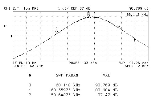 |
The same setup as above
("C?" means not calibrated) with the parallel combination
of the loop and cap fed from 50 Ohms and driving a 50 Ohm
load. The Q is about: Q = Fcenter / (Fhi - Flow) = 65 where Fhi and Flow are down 3 dB from the peak. But this may not mean much considering the source and load resistances. |
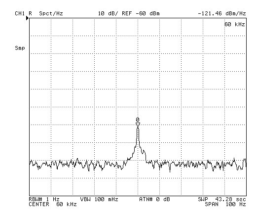 |
The loop and cap are series
connected for this spectrum plot. Taken at 9:30 am 19 Oct 2010 in my office, i.e. near a working computer and during the day. The signal is WWVB 20 dB above the noise!!! Note the "Smp" means the 4395A is in "Noise" mode, i.e. instead of peak detecting it's actually measuring power by squaring the I signal and squaring the Q signal then adding them and taking the square root To make the noise easier to see the video bandwidth has be lowered to 0.1 Hz rather than use averaging. The improvement may be because of the series LC connection, the spaced turns covering more of the ferrite or reducing the self capacitance, or something else? |
| Cap F |
Z Ohm |
L H |
|
| 0n1 |
26k5 |
70m3 |
|
| 0n47 |
5k64 |
14m9 |
|
| 1n0 |
2k65 |
7m0 |
|
| 1n8 |
1k47 |
3m9 |
|
| 4n7* |
564 |
1m5 |
|
| 6n8 |
390 |
1m0 |
|
| 10n0 |
265 |
0m7 |
|
| 56n0 |
47 |
0m1 |
| 4440501 | Method of automatic adjustment of self-contained radio-clock by means of time mark | na |
Apr 3, 1984 |
| 4768178 | High precision radio signal controlled continuously updated digital clock | PST |
Aug 30, 1988 |
| 4823328 | Radio signal controlled digital clock | PST empl |
Apr 18, 1989 |
| 5105396 | Autonomous radio timepiece | na |
Apr 14, 1992 |
| 5349570 | Method for operation of a radio-controlled clock and radio-controlled clock for use in an environment subject to interference fields | Temic | Sep 20, 1994 |
| 5528560 | Timepiece receptive of a broadcast time-signal for correcting a time error | Seiko |
Jun 18, 1996 |
| 5727022 | Method for improving the signal-to-noise ratio in a transmission system by the formation of area equivalents | Temic | Mar 10, 1998 |
| 5805647 | Method for detecting the beginning of time messages | Temic | Sep 8, 1998 |
| 5818851 | Method for detecting the time messages in the faulty signal of a time-signal transmitter | Temic | Oct 6, 1998 |
| 6456831 | Amplitude change time activated phase locked controller in a selective call receiver | NEC |
Sep 24, 2002 |
| 3281806 | Pulse
Width Modulation Representation of Paired Binary Digits,
Honneywell |
Oct 1966 |
| 3806656 | Decommutation
Device In Use In Particular in a Transmission Link with a
Missle |
Apr 1974 |
| 3939304 | Decommutator for extracting zero and one bits from a coded message of duration-modulated pulses |
| Material | Thermal conductivity (W·m−1·K−1) |
|---|---|
| Air | 0.024 - 0.025 - 0.0262 |
| Expanded polystyrene | 0.03-0.033 ((PS Only) 0.1-0.13) |
| Substance | Phase | Cp J/(g·K) |
|---|---|---|
| Air (Sea level, dry, 0 °C) | gas | 1.0035 |
| Air (typical room conditionsA) | gas | 1.012 |
| Aluminium | solid | 0.897 |
 |
 |
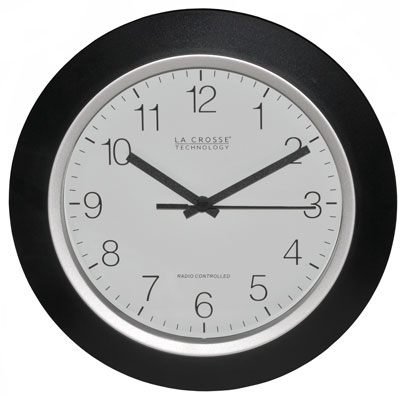
This is the newest WWVB La Crosse clock that receives the phase
modulation. I powered it up around noon and within 5 minutes
is was synced.
Fig 1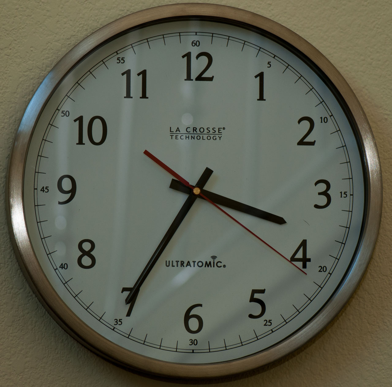 |
Fig 2 Returned 2020 June 11. For months now pretty much every day at very close to 4:00pm the clock would advance and stop very near 4:00pm. Sometimes is would not make it back to 4:00pm and so would be off by many hours for most of the day. We'll see how the warranty replacement works. 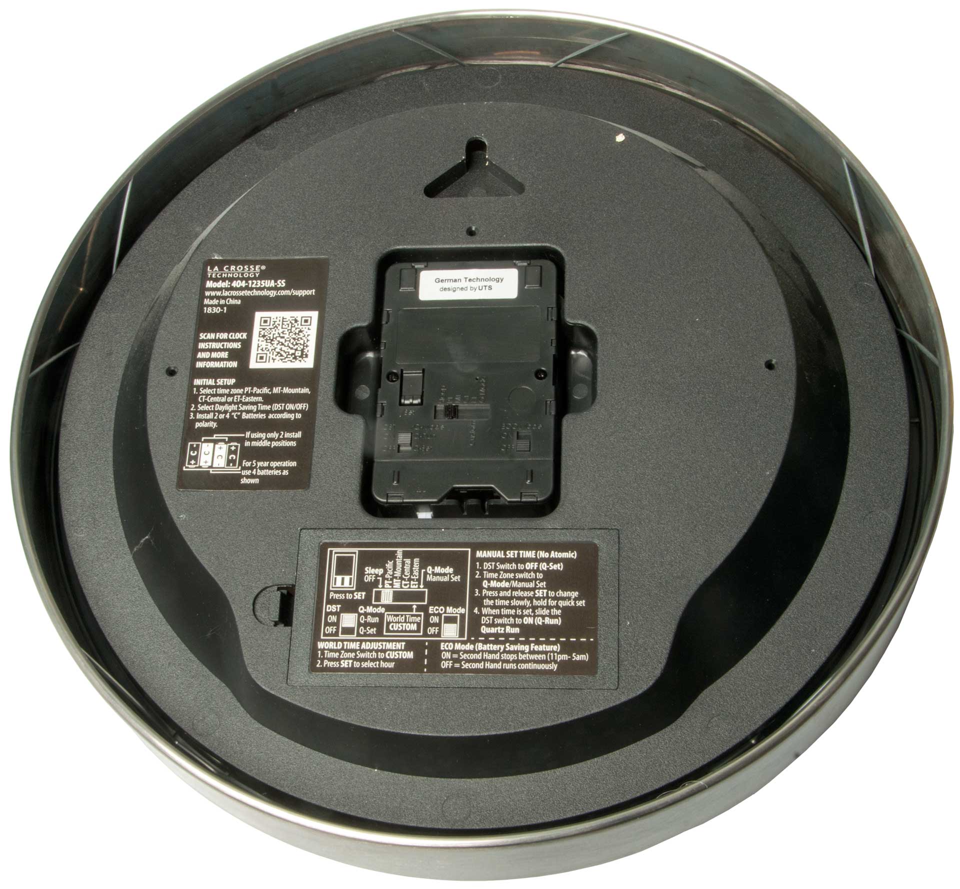 |
This clock developed the bad habit of running
forward at about 4pm, going 12 hours and stopping at about 4pm. This makes no sense since if it was slow it could just move ahead the few seconds needed. If is was fast it could just stop for a few seconds. I changed batteries, but the old batteries were not dead. Then it would move forward but not for 12 hours, so now was stopped at the wrong time. Sent is back to the factory for a warranty replacement. |
Replacement Ultratomic clock 25 June 2020
Fig 1 Box as receiver with broken tape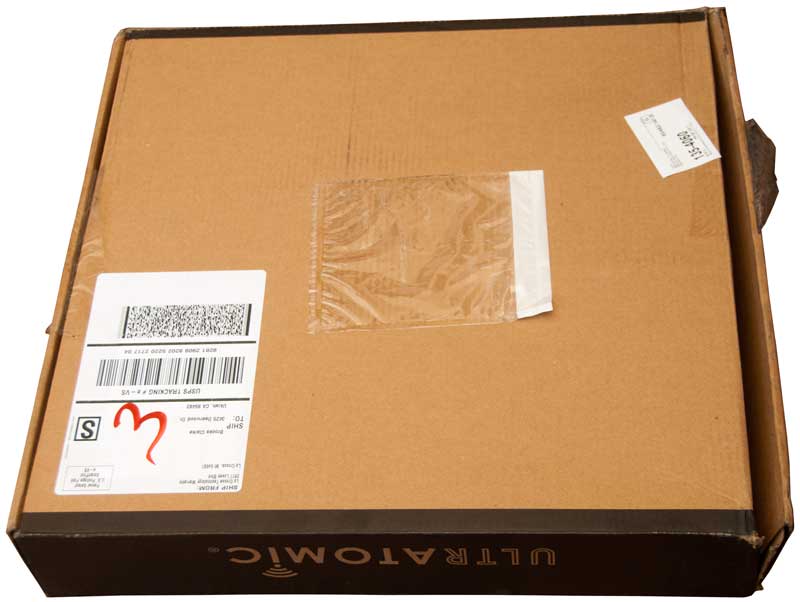 |
Fig 2 Interesting and good packing.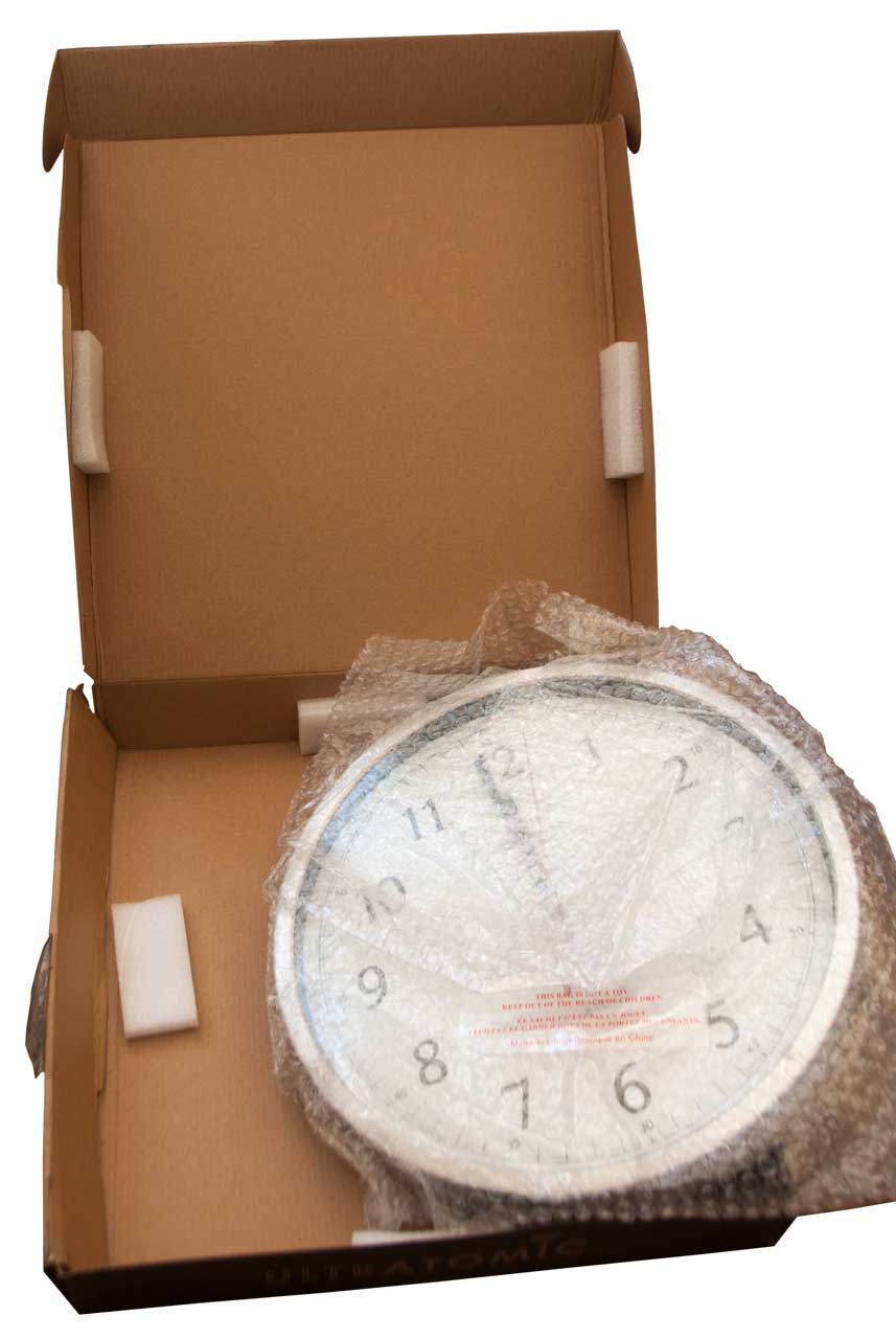 |
Fig 3 2:23pm As received: Zone: Pacific Time, DST: On, ECO: Off installed batteries. Clock ran forward to 4 pm. as of 2:54 no movement. 3:35 hour & minute hands move to 3:37 and then second hand starts. Seems OK.  |
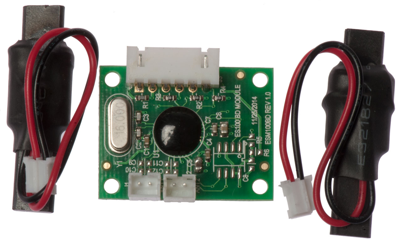
This is the chip used in the La Crosse WT-3102 WWVB Clock above that receives the phase modulation signal.
Universal-Solder - EVERSET ES100 -
LINKS and DOWNLOADS
- EverSet Technologies official website
- EverSet ES100 data sheet (PDF)
- Enhanced WWVB Broadcast Format (PDF)
- Download Documentation Package incl. Arduino Code
- AN-002 Energy Consumption
- AN-005 Antenna Considerations
Fig 1 SKU: 4260474039982
Close to Fig 9 in the EverSet ES100 data sheet
Fig 2
Fig 3 Advanced Development Kit
SKU: 4260474039999
has the IC missing from the Fig 1 version
WWVB
WWVB is upgrading their transmission so that receivers on the East coast will be able to synchronize even with a weak RF signal strength by adding phase modulation. The old constant phase (except for the small phase step) is not gone so receivers that locked to the carrier phase, like the HP 114 and a bunch of other frequency standard receivers will no longer work in stock format. There's talk of a circuit that can be added between in input and receiver that will remove the phase modulation and do that without the degradation in signal to noise ratio that a squaring circuit introduces, but I haven't seen one yet.
Modes:
Mode
Min CNR dB
Rate (bits/second)
Sync (bits)
Frame Period
How Often
Normal
10
1
13
1 min
1 minute
Message
10
1
1 min
infrequent
Fast
30
100
630 ms 10 sec
Medium
-3
1
106
6 min
30 minutes
Long
-13
1
1020
17 min
once per day
La Crosse Model # 404-1235UA-SS - makes use of the new phase modulation WWVB signal "UltrAtomic Time" - Leapsecond.com - see WT-3102 above
http://www.nist.gov/pml/div688/grp40/wwvb.cfm is the NIST web page talking about the new phase modulation format.
http://www.nist.gov/pml/div688/grp40/upload/NIST-Enhanced-WWVB-Broadcast-Format-1_01-2013-11-06.pdf is the paper, but does not cover all the different formats.
WWVB Time signal Broadcast: An Enhanced Broadcast Format and Multi-Mode Receiver, Liang, Eliezer, Rajan & Lowe, IEEE Communications mag. May 2014.
New NIST Time Code to Boost Reception for Radio-Controlled Clocks -
This paper goes into some detail about the different frame length messages. There are a number of references with links.
Information on Time and Frequency Services - suitable for NTP
JJY - The Method of Emitting Standard Time and Frequency Signal Emission -
MSF Radio Time Signal
SMU - Yingsi Liang - publications (9 Aug 2014)
- Y. Liang, D. Rajan, O. Eliezer, “Receiver Design of Radio-Controlled Clocks Based On The New WWVB Broadcast Format,” IEEE Trans. Wireless Communications, accepted for publication.
- Y. Liang, O. Eliezer, D. Rajan, and J. Lowe, “WWVB Time Signal Broadcast: An Enhanced Broadcast Format and Multi-Mode Receiver,” IEEE Communications Magazine, vol. 52, no. 5, pp. 210–217, May 2014.
- Y. Liang, O. Eliezer, D. Rajan, A. Ramasami, W. Khalil, “Interference-Robustness Improvement in BPSK Receivers for the Enhanced WWVB Broadcast” in IEEE Texas Symposium on Wireless and Microwave Circuits and Systems, April, 2014.
- Y. Liang, D. Rajan, O. Eliezer, S. Balasubramanian, and W. Khalil, "A New Broadcast Format and Receiver Architecture for Radio Controlled Clocks," in IEEE International Midwest Symposium on Circuits and Systems, pp. 1128 - 1131, August 2013.
- Y. Liang, H. Liu, and D. Rajan, “Optimal Placement and Configuration of Roadside Units in Vehicular Networks,” in IEEE Vehicular Technology Conference, pp. 1–6, May 2012.
- Y. Liang, O. Eliezer, and D. Rajan, “Optimization of Cosine Modulated Filter Bank for Narrowband RFI,” in IEEE GLOBECOM, pp. 1-5, December 2011.
- O. Eliezer, T. Jung, R. Lobo, M. Appel, Y. Liang, D. Robbins, and P. Nelsen, “A Multi-Mode Software-Defined CMOS BPSK Receiver SoC for the Newly Enhanced WWVB Atomic Clock Broadcast,” in IEEE Radio Frequency Integrated Circuits, June 2014.
- J. Lowe, M. Deutch, G. Nelson, D. Sutton, W. Yates, and P. Hansen, O. Eliezer, T. Jung, S. Morrison, Y. Liang, D. Rajan, et al. “New Improved System for WWVB Broadcast," in 43rd Annual PTTI Meeting, 2011.
- Y. Liang, D. Rajan, O. Eliezer, “Sequential Frame Synchronization based on Hypothesis Testing with Unknown CSI,” Manuscript in preparation.
- Y. Liang, D. Rajan, O. Eliezer, “Design of Non-linear Block Codes Given Unequal A-priori Message Probability,” Manuscript in preparation.
- Y. Liang, D. Rajan, O. Eliezer, “Design of Sync Word Given Unequal Energy per Bit,” Manuscript in preparation.
Patents
Many of these have some amount of duplication.
8270465 Timing and time information extraction from a phase modulated signal in a radio controlled clock receiver, Oren E. Eliezer, Xtendwave LLC , 2012-09-18, Patent Citations (55) (1965 - 2010) -
8331201 Leap second and daylight saving time correction for use in a radio controlled clock receiver, Oren E. Eliezer, Xw Llc, Grindstone Capital, Llc, Xw Llc Dba Xtendwave, Dec 11, 2012, 368/47, 375/329, 375/316, 368/28 - "The one second/one hour corrections are scheduled to occur when they should take place and the correction is applied exactly when DST or leap second is to go into effect, without having to receive anything around the time of the correction."
8605778 - Adaptive radio controlled clock employing different modes of operation for different applications and scenarios
8659457Self-compensating digital-to-analog converter and methods of calibration and operation thereof,Oren E. Eliezer, Ryan Lobo, Mark Appel,Xw, Llc.,Feb 25, 2014,341/120Not clock related
8774317 - System and Method for Phase Modulation Over a Pulse Width Modulated/Amplitude Modulated Signal for Use in a Radio Controlled Clock Receiver - Phase Modulation
20130121399 - Timing and Time Information Extraction in a Radio Controlled Clock Receiver -
8300687 of the same name but issued Oct 2012?
20130051184 Real-time clock integrated circuit with time code receiver, method of operation thereof and devices incorporating the same,Oren Eliezer, Thomas Jung, Steve Morrison, Mary Cooley, Xtendwave LLC , List of patents by Xw Li G04R20/08 Setting the time according to the time information carried or implied by the radio signal the radio signal being broadcast from a long-wave call sign, e.g. DCF77, JJY40, JJY60, MSF60 or WWVB- Citations (1987 - 2004)
20120082008 Low Power Radio Controlled Clock Incorporating Independent Timing Corrections, Oren E. Eliezer, Aditya Awasthi, Xtendwave LLC, 2013-09-10,H04W56/0035 Synchronisation arrangements detecting errors in frequency or phase - Patent Citations (57) (1965 - 2011)-
DCF77
The phase modulation system is similar to the one used on the German DCF77 time station, so a receiver that works for it might be modified to work with WWVB.
Elector magazine for Jan 2002 has an article by Steve Marchant of the UK on a DIY DCF77 receiver. Marvell Consultants - DCF77
Blikenlight - The Clock - by Udo Klein in Germany a DCF77 receiver shield for Arduino. The hardware front end is a commercial module (the larger the loopstick the better).
Micro Analog Systems Oy is making what appears to be a family of time code receiver modules similar to the C-max (MAS6180C.pdf). In addition they offer a family of time code test equipment.
I've asked if their RC-88 signal generator has both AM and phase modulation in the WWVB mode.
Universal Solder - CANADUINO 60kHz Atomic Clock Receiver Module V3 WWVB MSF JJY60 (MAS6180 based) -
The new version includes 74HC14 buffering of the inputs and outputs as well as a ME6209 (pdf) 3.3V regulator
older version of MAS6180 from 2016 (this was a raw 6180 on a PCB)
Citations (16)
I've had a couple of encounters with RFI recently in regard to WWVB receivers.
The first was in relation to the La Crosse UltrAtomic wall clock. The factory replaced it 25 June 2020 because at 4:00 pm every day it would go crazy. After that in November 2021 I got a Starlink 2-way satellite system that comes with a router. Because for each the past five years there has been a wildfire within a few miles of my house (Oct2017 & scroll down from there) I have multiple Internet Service Providers (Wiki: ISP) since none of them has all the attributes I want (Reliable, Fast, Low cost). So I now have three ISPs and three WiFi routers (Wiki).
All three of these routers are within 15 feet of the UltrAtomic wall clock. My guess is that they are causing the problems. I plan to get a ladder and move the clock far from the routers and see if it starts telling time. Since the arrival of Starlink it has NEVER told the correct time. The clock stopped working and I thought it needed batteries, but getting stuff moved to make room for a ladder caused me to just ignore the clock. Every now and then the hands moved, but that seemed like a weak battery symptom.
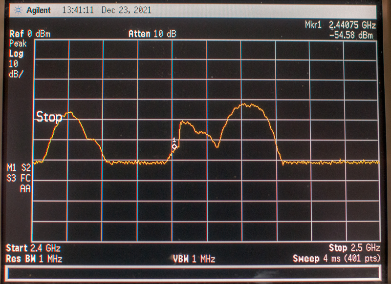
2.4 Ghz WiFi Band from Agilent E4404B Spectrum Analyzer
AT&T/D-Link router 5 to 7 squares from the left.
WISP router 4 to 5 squares from the left
Starlink router 1 to 2 squares from the left.
...the second RFI case..... A friend received a La Crosse S84107 Wireless Forecast Station that includes a WWVB receiver. When first installed it did not synchronize to WWVB on neither an East-West axis nor on a North-South axis. The same table held chargers for an iPhone and iPad as well as a couple of cordless phones. When all of those were moved over ten feet away the S84107 gets a solid signal. I have not tried to figure out which is the problem but note that both the iPad and iPhone contain Wifi transceivers that often emit signals even when they are in standby mode. I think cordless phones only emit signals when in use, so my guess is that the WiFi is the problem with both La Crosse devices.
Note that RFI (Wiki) is usually associated with what's called "in band" signals, i.e. when the interfering signals are in the same band as the device receiving the interference. In this WWVB case the interfering signals are at a very different microwave frequencies but are causing the WWVB receivers to malfunction. This has been a problem for as long as there have been radio receivers. The better receivers have filtering that rejects most if not all out of band signals. But modern receivers are designed with front ends that accept everything and these designs are susceptible to out of band interference. The WWVB problem may not be just the front end but could be anywhere since microwave signals could get into any part of the receiver and cause problems.
[an error occurred while processing this directive] page created 22 Sep. 2003.