Impedance Measurements
© Brooke Clarke, N6GCE 2003 - 2021Impedance of Transmission Lines
Accuracy of Impedance Measurements
Guard
Impedance Measuring Instruments
Low Frequency Bridges
RF Bridges
43961A V/I Test Set
4395A Network Analyzer using a reflectometer or coupler
4395A Network Analyzer in Transmission mode (Z:TRANS)
E4980A Precision LCR Meter
Boonton 160 Q-Meter
HP 16091A Axial Lead Coaxial Test Fixture
Patents
Key Documents
Related
Links
How does an Impedance Measurement differ from other measurements?
Terminals
Impedance measurements are typically, but not always, made on fundamental electrical components like resistors, capacitors, inductors, crystals, etc. that do not have coaxial connectors. Devices like amplifiers that have coaxial connectors are typically designed to have an impedance that matches the connector impedance like 50 or 75 Ohms and can be tested using a network analyzer with high accuracy.
How you connect a DUT that does not have any connectors is important. Whatever fixture you use is going to have it's own parasitic capacitance and inductance and if it is a single coax type will have some port extension electrical length.
The HP family of LCR meters that use the four BNC(f) connectors have a large number of test fixtures available. Also the 43961A uses a standardized APC-7 type of test fixture.
For lower frequencies the test fixture is less critical and simple test leads can be used. When using a swept impedance measurement, like the 4395 (combo box SA, VNA, ZA), it's easy to see the effect of lead inductance as the frequency goes up, and set the stop frequency below this point.
Magnitude of Impedance
Components without connectors may have impedance values ranging from milli Ohms to hundreds of meg Ohms that are a function of frequency. Coax and twisted pair impedance ranges from about 50 Ohms for common coax to 600 Ohms for open wire phone lines.
Impedance of Transmission Lines
Accuracy of Impedance Measurements
Different measurement methods give results with different accuracies. One way to look at this is to plot impedance on the Y-axis and frequency on the X-axis of a graph and draw accuracy profiles. See Agilent publication 8 Hints for Successful Impedance Measurements, App Note 346-4, pub # 5968-1947E, page 2, Figure 0-1 Accuracy Profile.
You can see that a network analyzer using either a reflection (bridge) or transmission impedance measurement method has good results for impedance in the 5 to 500 Ohm range over the widest frequency range. The Auto-Balancing Bridge instrument has the broadest impedance magnitude coverage with 1 milli Ohm to 100 Meg Ohm impedance range, but with a frequency range limited to 20 Hz to 110 MHz. The V/I (V over I) method is close to the Auto-Balancing Bridge but is inside it for both frequency and |Z|.
This information is also in the Impedance Measurement Handbook (see Related below) but was also put into the 8 Hints publication because it's an important concept.
Guard
The obvious use of the guard voltage is to eliminate cable to cable capacity from a measurement. But it can also be used to control parasitics in a measurement. For example if you want to measure the capacitance of one of the diodes in a ring or bridge quad the classical methods are to measure the capacitance of one of the diodes, the adjacent measurement, with the capacitance of the remaining three diodes in series in parallel with the measured diode. Another way is to measure the capacitance across a diagonal which would be the same as the capacitance of a single diode if they are all the same. The problem with either of these is that there are parasitic effects as well as unintended guarding effects.
Now consider what happens if when making a diagonal capacitance measurement on a quad diode and guard is applied to the other two diagonal terminals. The test terminals and the diagonal terminals will be at the same potential and by definition the capacitance will be zero and it is in practice. So if there was unintentional partial guarding when making a diagonal measurement the result is to lower the true capacitance making for an error somewhere up to 100%.
Now consider what happens if when making an adjacent capacitance measurement on a quad diode and guard is applied to the other two terminals. The capacity of the three other diodes will be eliminated leaving only the single diode's capacitance in the measurement. If this measurement is repeated for each of the four diodes you can see how well they are matched.
See the HP 4274 - HP 4275 LCR Guarding example.
Impedance Measuring Instruments
Low Frequency Bridges
HP, now Agilent, offers a number of LCR meters that are of the Auto-Balancing Bridge type. The HP 4260 and 4332 are analog LCR meters of this type and use three 5-way binding posts to connect to the DUT. One of them is a guard that drives the shield on a coax cable so that no capacitance will be seen between the coax center conductor to the other wire lead. Thus improving the accuracy for low value capacitance measurements.
Later instruments, like the 4274, 4275, 4284 use four BNC(f) connectors on the front panel and a more elaborate scheme that not only guards the connection to the DUT but also cancels magnetic coupling between the test leads. This is not so important when a fixture, like the 16047A, is connected directly to the front panel, but is vital when making a remote reading, like when using an automatic tester or binner.
Note that the shield of one of the coax lines is NOT grounded but is part of the guard system. You can check with an Ohm meter between the BNC-f shells and the chassis ground to confirm this. So when making any test fixture were cables are used it's important to keep them insulated from each other (i.e. don't use non insulated coax like 0.141") and it's important that the cables are in a fixed relationship with each other. So cable clamps are good and cables that are flapping around loose are poor. since the magnetic loop is changing.
The shields are connected together at the fixture end of the cable and that terminal is guard. Guard should be floated relative to chassis ground.
ZM-4 DC bridge - designed for work on telephone lines
Heathkit IB-5281 LCR Impedance Bridge - manually nulled 1 kHz bridge, battery powered
HP 4260A ZM71A/U Universal Bridge - manually nulled 1 kHz bridge, line powered
HP 4274A & HP 4275A 4-Terminal Pair Auto Balancing LCR Bridges -
HP 4332A LCR Meter - analog 3 Ohm to 1 M Ohm, 3 pF to 1 uF, 3 uH to 1 H, line powered
Marconi TF-2700 manually nulled 1 kHz Universal LCR Bridge, battery powered
Omega-T TE7 Antenna Noise Bridge - uses noise diode as test signal covering HF radio frequencies 1 to 30 MHz., battery powered
ZM-11 AC LCR Bridge - designed to test components used in typical tube type equipment including cap leakage, line powered
Der EE DE-5000 - 100-240VAC to 9VDC (cneter +) @ 660mA adapter; USB-A to USB-Mini cable; PC connection CD-ROM with DE-5000-USB adapter; TL-23 Guard Test Lead; YL-21 Red & Black Test Leads; TL-22 Tweezer for SMD testing; Carry Case
RF Bridges
HP Memory Org -Direct Measurement of Impedance - and the advent of S-Parameters
43961A V/I
Test Set
The HP / Agilent 43961A is a test set originally made for use with the HP 4396A combo box Network, Spectrum & optionally Impedance Analyzer. It covers 100 kHz to 1.8 GHz and will connect to many HP/Agilent network analyzers, but because of the V/I operation can only be used on the 4395 or 4396 network analyzers that have the option -010 firmware. This is because the A port output is proportional to the Current through the DUT and the R port output is proportional to the voltage across the DUT. Thus an A/R measurement yields I/V (=1/Z). Also the math for the calibration and measurement are completely different from what is used for a reflection measurement. For example with a reflection measurement the A/R value for an open and short have the same magnitude (normalized to 1.0 and only differ 180 degrees in phase. This is very different from a V/I measurement where a short has near zero for V/I and an open is near infinity.
I'm working on some code that will allow this test set to be used on any HP / Agilent network analyzer that has IBasic. Stopped work on this when I found the IBasic in the 4395 does NOT support the COMPLEX data type that is supported by normal Rocky Mountain Basic.
HP 4191 & 4193 patent 5345182 Impedance meter capable of performing measurements at high precision over wide impedance and frequency ranges Sep 6, 1994 324/649; 324/522; 324/654; 324/713 - the V/I method
4395A Network Analyzer using a reflectometer or coupler
The 4380A 8-Port test set can be used with the 4380S System software to measure the impedance of CAT5 LAN cable from 1 kHz to 500 MHz. When the 4396A/B Network Analyzer is used 100 kHz to 1.8 GHz can be mesured. Typical values for impedance are in the area of 120 Ohms for Unshielded Twisted Pair (UTP) and 50 Ohms for coax.
A Mini Circuits ZFDC-10-1 Coupler can be used for reflection measurements over the 50 kHz to 500 MHz range. This can be done simply in the A port only mode, or with the addition of a power splitter in the A/R port mode that corrects for source level variations automatically.
4395A Network Analyzer in Transmission mode (Z:TRANS)
By inserting the DUT in series between the source port (or the output of a power splitter when using A/R) and looking at the forward transmission (S21) you can see the device impedance will effect the transmission plot. Where the impedance is low the insertion loss will be low and so forth. By using the MEAS/CONVERSION/Z:TRANS function the 4395A converts the S21 plot into either a linear or log |Z| plot. This is the method used in the E5100() and E4916 Crystal Impedance meters.
E4980A Precision LCR Meter
This seems to be the only LCR meter now offered (July 2007). Over $15k. Smaller than the rack sized instruments like the 4284 and with most of their capability.
Boonton 160 Q-Meter
Spent years (full time) studying Q. It takes specialized measurement instruments to make accurate Q measurements. Understanding how Q behaves vs. frequency has a steep learning curve. One result of this study was the construction of an excellent crystal radio. See: Inductors
There is an accessory box for the HP 4284 LCR meter that has terminals on the top that match the 160 Q-meter and a motorized capacitor inside so it can make resonate Q-measurements.
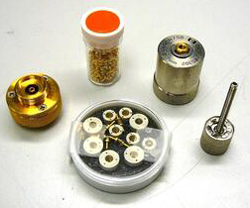
HP 16091A Axial Lead Coaxial Test Fixture
Clockwise starting at left:
1. APC-7 connector saver
2. Lead adapter sleeves to be soldered on axial components
3. Main 7mm bore test fixture (also used as APC-7 Open for Cal)
4. Screw to push shorting plunger
5. Shorting plungers. Note two sizes: 7mm and a smaller size.
An axial component would have a couple of the adapter sleeves soldered and the lead length trimmed. The component would be plugged into the connector saver. The shorting plug would be pushed down into the main body far enough that the main body can be mounted on the connector saver. Then the feed screw would be turned until the shorting plug had just bottomed.
This is a coaxial part with male APC-7 threads on one end. The other end has a brass fitting with small threads to hold a plunger. There was a small vial of plugs with a hole in the center for the tip of the plunger and spring fingers all around that fit the inside 7 mm bore of the fixture. This allowed testing small axial parts. There was a related part what was an APC-7 base for this part to screw onto. The idea is that the pin on the DUT may damage the APC-7 connector on the impedance test instrument so this was a protector.
This was an accessory for the HP 4191 but also showed up in many later impedance measuring instruments.
There were two main bodies, one with a 7mm bore to match APC-7 connectors and another with a smaller bore. The smaller bore main body is not shown in the above photo.
Patents
2480163 Negative Feedback Amplifier,
3056082 Electrical Measuring Instruments - DC
3100879 capacitance sensing circuit
4306297 Apparatus for measuring the vector voltage ratio of two A.C. signals, Noriyuki Sugihara, Takashi Yoshida, HP, 1981-12-15, -
4409543 Impedance meter, Noriyuki Sugihara, HP, 1983-10-11, -
An Automatic Wide Range LCR Meter - HPJ Sept 1976 - 4261A - 16061A Banana plug fixture precursor to the 16047 BNC fixture.4481464 Apparatus for measuring time variant device impedance, Hitoshi Noguchi, Tomoyuki Akiyama, Hideo Akama, Hideo Okara, Hisao Yoshino, HP, 1984-11-06, -
Multifrequency LCR Meters - HPJ Feb 1979 - HP4274A & HP 4275A
HPJ March 1974 - An Automatic, Precision 1-MHz Digital LCR Meter - 4271A4588970 Three section termination for an R.F. triaxial directional bridge, S. Bruce Donecker, Julius K. Botka, HP, 1986-05-13, -
EP0150336 Broadband radio frequency directional bridge, S. Bruce Donecker, Julius K. Botka, HP, 1985-08-07, - 45 MHz - 26.5 GHz, also triangular splitter,
JPH01162166 Q measuring apparatus, Tomio Wakasugi, YHP, 1989-06-26, -
JPH0375574 Tuning method and q meter, Tetsuaki Ikoma, YHP, 1999-06-21, - HP 42851A Precision Q Adapter
JPH03239968 Q meter error correcting method and q meter, Tetsuaki Ikoma, YHP, 1999-11-15, - a method that works even when the resonating cap does not have enough range.
JPH05172875 Electronic element measuring device, Hideji Tanaka, Yasuaki Komatsu, YHP, 2000-10-23, - using a 4-terminal pair cal standard on a 3-terminal pair meter.
4888701 Apparatus for measuring vector voltage ratio, Tomio Wakasugi, Hideshi Tanaka, HP, 1989-12-19, -
4992740 Apparatus which uses a simulated inductor in the measurement of an electrical parameter of a device under test, Tomio Wakasugi, HP, 1991-02-12, -
5086278 Circuit element measuring method and apparatus, Hideki Wakamatsu, Shinya Goto, HP, 1992-02-04, - 4261A, 4274A & 4275A LCR meters.
5345182 Impedance meter capable of performing measurements at high precision over wide impedance and frequency ranges, Hideki Wakamatsu, HP, Sep 6, 1994 324/649; 324/522; 324/654; 324/713 - the V/I method, 1MHz to 1 GHz
EP0661548 Impedance meter, Hideki Wakamatsu, HP, 1995-07-05, - uses a triax cable,
5463323 Impedance meter, Hideki Wakamatsu, HP, 1995-10-31, - uses a triax cable, Remote V/I method
5523693 Balanced signal source, Koichi Yanagawa, Jun 4, 1996, 324/651; 333/149; 333/25 - DC to 10 Mhz reflection bridge with >40 dB directivity
References:
5600249 Determining contact quality of an impedance meter, Kazuyuki Yagi, Feb 4, 1997, 324/537; 324/525; 324/715; 340/652
6768952 System and Method of Measuring Low Impedance, Isaac Kantorovich, Jul 27, 2004, 702/65; 702/64; 702/77 - aimed at power supply for PC
7148694 Contact impedance test circuit and method, Martin L. Stabler (US Navy), Dec 12, 2006, 324/421; 324/709; 324/713 -
| 3919504 | Method and apparatus
on in-circuit testing of a group of
sequentially-operated system output bistable devices |
November 1975 | Crosley et al. |
| 4516076 | Fault detection arrangement for relay switching system | May 1985 | Pillari et al. |
| 5138264 | Apparatus for measuring electrical conductivity | August 1992 | Seki et al. |
| 5491424 | System for measuring contamination resistance | February 1996 | Asar et al. |
| 6025726 | Method and apparatus for determining three-dimensional position, orientation | February 2000 | Gershenfeld et al. |
| 6323669 | Apparatus and method for a contact test between an integrated circuit device | November 2001 | Kang |
| 6337573 | Contact test circuit | January 2002 | Ronaccio et al. |
| 6784671 | Moisture and density detector (MDD) | August 2004 | Steele et al. |
| 6967483 | Apparatus and method for determining contact dynamics | November 2005 | Kwark |
Key Documents
Agilent Impedance web
page http://www.agilent.com/find/impedance
The HP Impedance Measurement Handbook (5950-3000)
written by Makoto Honda is an excellent reference on impedance
measurements.
The fixtures needed for different parts are covered in
Accessories Selection Guide for Impedance Measurements (5965-4792E).
S-Parameters: HP
App Note 95; Keysight
App Note 5952-1087
Related
Digital Multi Meter - some have capacitance ranges
ESR and Capactance Meters - for in circuit location of bad capacitors (even without documentation)
Battery Tester - Resistance and Voltage
EVB ESR Tester
Millen 90651 Grid Dip Meter -
GR 650-A Impedance Bridge predecessor of the GR 1650A and GR 1650B
HP 415 VSWR Meter - can be used with a detector and slotted line to determine complex impedance or with any 1 kHz modulated signal as sensitive detector.
HP 4260A Universal Bridge
HP 4274A & HP 4275A LCR Meters - 4-termianl pair
HP 4328A Milliohmmeter - for low resistance measurements using an AC test signal to avoid dissimilar metal DC offsets
HP 4332 LCR Meter -
HP 4260A Universal Bridge
HP 4261A LCR meter
HP 4274 & HP 4275 LCR meters
HP 4395A combined Network, Spectrum & Impedance Analyzer 0 to 500 Mhz
Inductors
Capacitors
KS8455L2 Line Loop Tester Telephone Installers & Repairman's Meter - measures capacitance in "points" for line length and number of ringers
Lunch Box telephone Subscriber Loop Analyzers - include various line impedance functions
Stanford Research SR715 LCR Meter - the basis of the HP 4263
TF2700 Marconi TF-2700 Universal Bridge
Zo Transmission Line Impedance (is not constant with frequency)
ZM4 - DC Resistance Bridge
ZM-11 - Capacitance-Inductance-Resistance Bridge
Links
Dabbledoo Electronics Encore/Impedance Measurements -