Description
This web page is the result of finding that the HP 4395A can measure crystals in the Network Analyzer mode where the crystal is in series with the center conductor of a coax line. The marker can be read to a milli Hertz even through the RBW is set to 2 Hz, not sure of the significance of those extra digits if any, but the plots look very smooth.

The equivalent circuit of a crystal unit is the series combination of the motional equivalents of inductance (L1), capacitance (C1) and resistance (R1) and in parallel with this string the package and parasitic capacitance (C0). If a load capacitor (Cl) is used in the application circuit it is in series with the crystal.
The Red micro grabber can easily be moved from the active crystal lead to the other lead thus providing a through connection without moving much of the setup. Above 5 MHz the effect of the lead wires starts to show up and at 50 MHz this setup is not very good. For working with higher frequency crystals some sort of test fixture to hold the crystal and ground the case would be needed.
The Phase vs. Frequency plot shows zero phase at 999.936495 kHz while a LOG(mag) plot taken very close in time shows the Fr peak at 999.937725 kHz. different by about 1 Hz or about 1ppm.
Official Method
When test instruments like the
HP/Agilent E5100 are used for crystal measurements a circuit
than transforms the 50 Ohm test setup down to maybe 10 Ohms (as
far as I can remember) is used on each side of the
crystal. This is just a resistive matching circuit.
It also adds some padding on either side of the crystal and so
removes connector and cable VSWR effects. If a dedicated
fixture was made it would be good to build in the pads.
Measuring
When the frequency is more than a percent or two away from the crystal frequency then the impedance looks like just C0. Which for the Jameco 14349 1 MHz crystal is 1.99 pF. This crystal is very similar to the one in the HP 8406A Comb Generator.
Fc0 = 990.000000 kHz @ -58.179 dB -> C0 = 1.99 pF
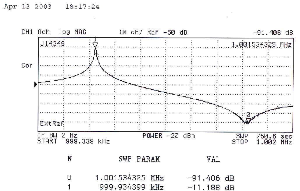
Fr = 999.934399 kHz @ -11.188 dB -> R1 = 262.58 Ohms
Fa = 1,001.534325 kHz @ -91.406 dB
C1 = 2 * Ct * deltaF / Fs then C1 = 6.35e-15 or C1 = 635 fF
where Ct = C0 + CL and CL = 0 for this case
and
If L1 = 1/[C1 * (2 * PI * F)2] then L1 = 3.99 H
Q = 95,425
Images:
Xtal_ec.xls - spreadsheet to find equivalent circuit values and then plot a simulated response
4395A Screen Dump showing Fr (mkr 1) and Fa (mkr 0)
Calculated results on Excel spread sheet
Plotted results on Excel spread sheet - Note that on both the network analyzer and on the Excel plots that the peak is often missed because of the actual points being used. On this plot the Fr peak looks like it's at -32 dB, but it's really at -11 dB and will show up on the Excel plot if the actual value of Fr is inserted into the data set.
Notes on calculations
Rather than using just a single point to calculate the equivalent circuit values it would be better, in my opinion, to do a curve fit and use a lot of points. That may improve the accuracy of the final equivalent circuit values.Notes on 4395A setup
By setting the BW/Ave\ IF BW = 30 and using SWEEP\# of Points = 201 you can make quick plots to see what's where.
But for making actual measurements you need to set the Start frequency just below Fr and Stop frequency just above Fa.
This can be done by setting the marker where you want the start or stop to be and then pressing MARKER--->\(and either MKR->Start or MKR->Stop). To scale the display press Scale Ref\AUTO Scale. And set the Sweep/# of Points to 801. Of course it goes without saying that a good external 10 Mhz reference should be driving the 4395A so that the marker frequency is right on, like a PRS10 Rubidium oscillator that is being disciplined by GPS.
Now remove the crystal and connect the through and press CAL\Calibrate Menu\Response\Thru and have a cup of coffee.
When it's done press "DONE", this is very important!
The sweep will start making measurement, so remove the through and connect the crystal then press Trigger\hold then Trigger\continuous to get the trace starting at the left.
Z Transformation Method
This is a similar method in that the crystal is connected in series with the center conductor, and NO power splitter is used for the "R" port, only a straight source to receiver works correctly. Under Measure <MEAS> softkey CONVERSION select Z:Trans.
After a response/thru calibration you can select Display LIN -where the display reads directly in Ohms for the impedance, LOG where the display can be converted back to Ohms using Ohms = 10 ^ (dB/20), or PHASE.
At series resonance, 3.593,615 MHz, the impedance marker shows 63.807 dB. You can do the math 10 ^ (63.807/20) to get 1.550 k Ohms, or easier, switch to Display Lin Mag and read the marker directly.
The parallel reas. freq is higher than 3.579545 MHz because of the capacitance of the Z:Tans fixture is higher than the design capacitive load for this Xtal.
I made the Z:Trans as a quick fixture for testing UTP pairs and so did not try to control or minimize it's capacitance.
The Parallel Resonance, with the approximate 65 pF from the Z:Trans test fixture is 3.600,072,5 MHz.
Both of the above plots were made using a very simple Z:Trans fixture that was made to measure Unshielded Twisted Pairs, see my white paper on the Low Frequency Zo of transmission lines (where the line is NOT loss less.) for a photo of the fixture.
To make a Z:Trans fixture for measuring crystals you would need to use a "lead swallowing" design and use a small variable capacitor to bring the load cap. to 20 or 32 pF, or some other standard value. The existing binding posts close to each other have way too much capacitance for to use for measuring Frequency at CL.
The existing Z:Trans fixture is fine for measuring the characteristics of crystals since the effect of the fixture capacitance can easily be backed out of the measurements with math.
My Test Equipment
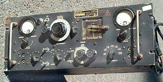
Crystal Activity Meter - Will oscillate with most (not the Jameco 14349) crystals showing that they work and allowing a rough frequency measurement.
TS-330/TSM Crystal Impedance Meter.jpg - TM 11-6625-536-14 can make spot frequency measurements and determine some crystal parameters.
HP/Agilent 4395A Combo Analyzer in Network Analyzer mode - will measure impedance (without the optional impedance firmware) to allow characterizing crystals.
Notes:
- The start and stop frequencies need to be set just below and just above the Resonant and anti-resonant frequencies respectively.
- The RBW needs to be as low as possible, 2 Hz for most Xtals in the 1 MHz range.
- There are a number of display FORMATs: LOG(mag) of the transmission (S21), Phase of S21, and Delay is interesting, but I'm not sure what you can learn from it.
- Still working on how to get to the equivalent circuit values from the measured data what data points need to be extracted.
Links
Crystals web page - general info about Crystals