FR-149B/USM-159A Frequency Meter
© Brooke Clarke 2016 - 2026USM-159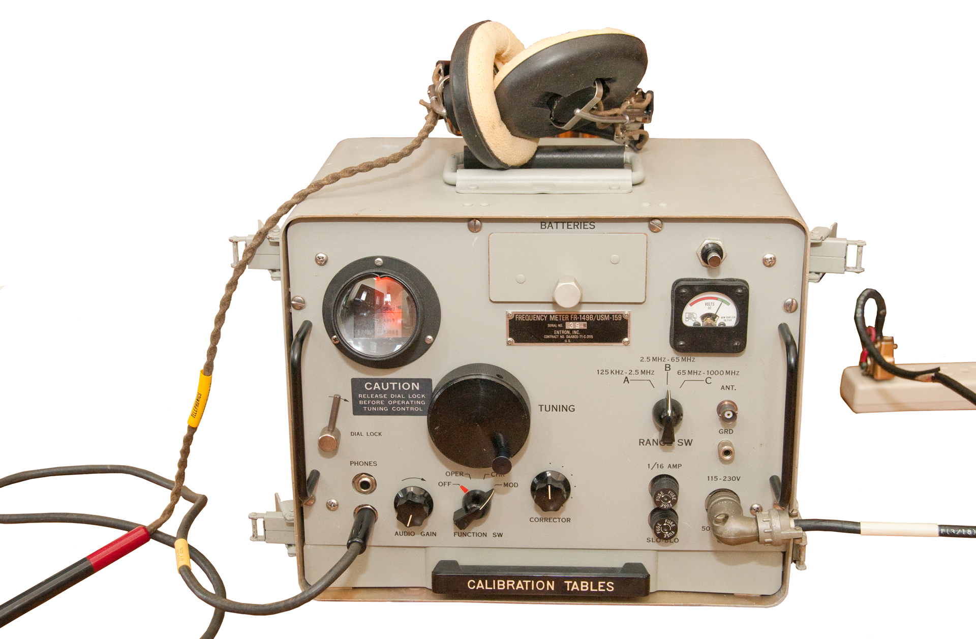 |
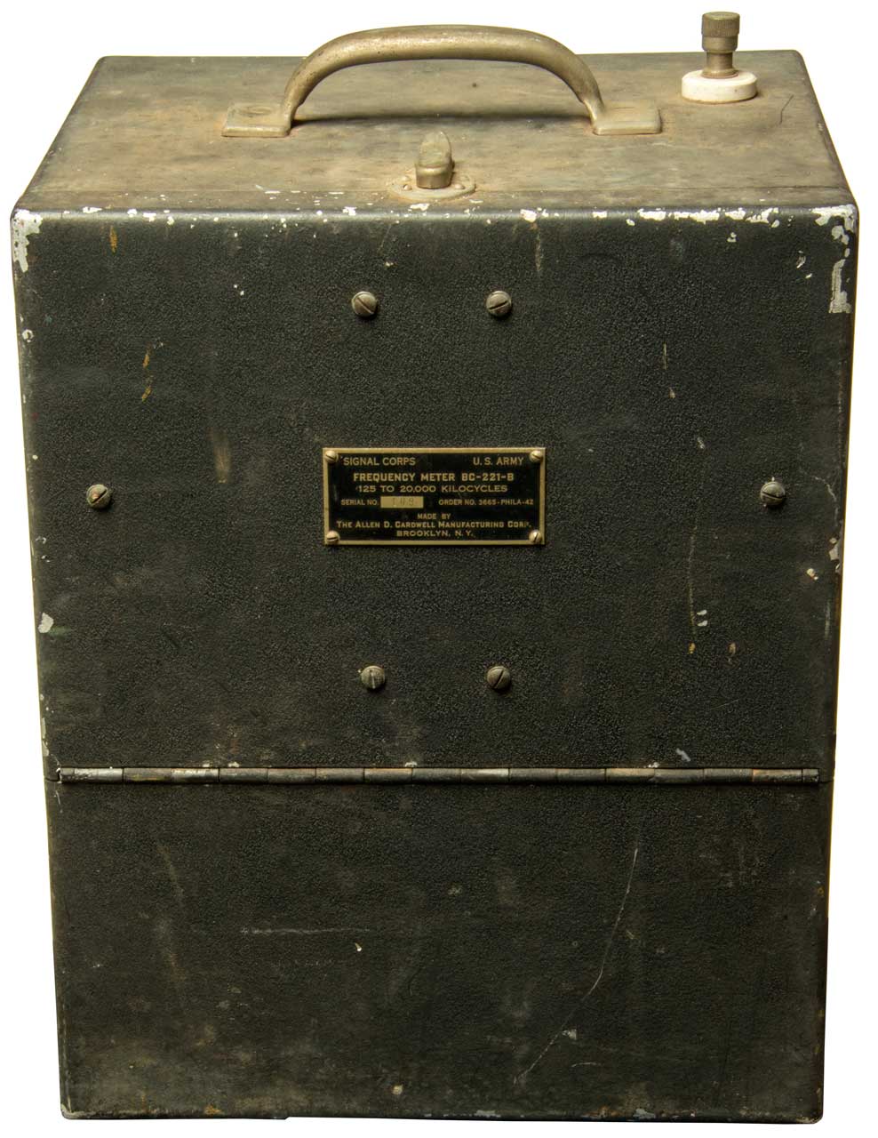
BC-221-B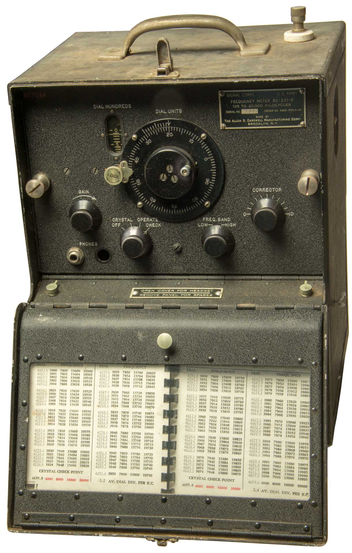
|
LM-18 |
History
Harmonics Everywhere
Description
Spectrum Plots
Manuals
Photos
BC-221
LM 18
Patents
Related
References
Solid State Tube Replacements
Links
Background
When tuning a receiver to a broadcast station that transmits all the time you just listen for the station and tune for best signal. But that can not be done for utility or military stations that transmit only for a short time. For these you need a tuning accuracy that is precise enough to center the transmitted signal in the radio's receive bandwidth. For a CW signal this is on the order of tens of cycles.
This type of heterodyne frequency meter (Wiki) was made during the time of analog radios where there was a tuning dial on receivers whose accuracy was poor. By that I mean that if you tuned to the frequency of a station that was not then transmitting and waited for a transmission you may not hear the station when it did transmit because the calibration error of the radio was greater than the bandwidth of most stations. So there needed to be an accurate way to tune the receiver as well as the transmitter.
One way was with a crystal calibrator. I have a Heathkit HD-20 Crystal Calibrator that uses a 100 kHz crystal and so had a harmonic every 100 kHz. This would allow calibrating the receiver to the nearest 100 kHz which might cover 10 stations. This was just a small box with an on/off switch and a terminal for a short wire antenna that would allow coupling the signal to a receiver. You could set the receiver dial so it was right on one of the harmonics then the dial accuracy would be improved. Note after setting the dial an some harmonic the error would increase away from that frequency so that if you wanted to receive at some other frequency a few MHz away the dial would no longer be accurate.
The early "frequency meters" were not frequency meters in the sense that they measure frequency. See the HP Memory Project for very early test instruments the measure frequency and my HP AC4A tube type decade counter web page for more on that. Instead they were precision oscillators that could be used to calibrate a receiver, or by listening to a beat note using headphones compare the oscillator output to the signal of another oscillator, like from a transmitter that needed to be set to a precise frequency.
As part of my general interest in precision time and frequency now and then I considered buying a BC-221 Heterodyne Frequency Meter. These were W.W.II vintage precision oscillators covering the 125 kc to 20 Mc used so that a receiver or transmitter could be tuned to the assigned frequency. The thing that's interesting about the BC-221 is that it's calibration book was custom made for each serial number frequency meter. There is a web page describing an automated method of making a new calibration booklet. That was needed because analog radio equipment was not accurate enough.
With the advent of synthesized radios based on a stable crystal reference oscillator the need for frequency meters declined. Although they were still in service to support the older analog radios for many decades.
Various Heterodyne Frequency Meters
Army; BC-221 (part of the SCR-211) TM 11-300;
TS-174 Hetrodyne Frequency Meter, 20 - 250 Mhz (LM-18/BC-221 type with cal book), 20 - 40 MHz VFO, TM 11-5044BC-906 (VHF)
A
TO 08-10-107.pdf
SIG 8-BC-906 Parts (A, B, C, D, &E) 1945
160 - 200
B
TO 08-10-107.pdf 160 - 220
C
TO 08-10-107.pdf 150 - 225
D
TO 08-10-107.pdf 160 - 220
E
TM 11-2623.pdf) 150 - 234
Navy; LM series for example the LM-13: 195 kHz - 4 MHz; TS-series for example the TS-323: 20 - 450 MHz; Navy nomenclature (a bunch of letters - a long number)
General Radio 720-A - looking for dates, patent numbers &Etc.
2367681 Ultra-high-frequency tuning apparatus, Karplus Eduard, Arnold P G Peterson, General Radio Co, App: 1941-12-10, W.W.II, Pub: 1945-01-23, - Butterfly capacitor -eliminates sliding electrical connections - for 100 to 200 MHz operation.
2578429 Ultrahigh-frequency tuning apparatus, Karplus Eduard, General Radio Co, 1951-12-11, - oscillator uses 6F4 acorn tube (AWA, Franks's tubes) makes use of cylindrical butterfly capacitor
FR-4U part of AN/URM-79 - mid 1950s, 30 tubes, interpolation oscillator, not at all portable.
History
The fundamental idea goes back to the 1930 Bell Labs patent 1947182.
1947182 Constant frequency apparatus, Philander H Betts, Bell Labs, App: 1930-06-07, Pub: 1934-02-13, -
The crystal mentioned is 100 kHz, not the 1 MHz of the more modern versions.
"This invention relates to constant frequency and it may be calibrated in harmonics of the apparatus, and particularly to apparatus which may be assembled into a compact and portable unit, and may be utilized to measure the frequency of an unknown wave, or produce a wave of known frequency, with great accuracy.
A feature of this invention is a piezo-electric crystal controlled oscillation generator, and means for comparing the frequency of an electric oscillation generator with waves produced thereby."
Betts also was issued patent 1984514, Constant Temperature Apparatus that uses a heater to maintain the crystal temperature, but the power required is too high for a portable unit. Instead the Constant frequency apparatus makes extensive use of temperature compensation.
Harmonics Everywhere
The mixer equation is:
IF = +/-m * RF +/-n * LOThe input circuit is designed to generate harmonics, the crystal oscillator is designed to generate harmonics and the Variable Frequency Oscillator is designed to generate harmonics. This is required since the VFO only has limited frequency coverage in the LM-series and the BC-series meters of 0.125 to 0.250 MHz or 2 to 4 MHz. The crystal oscillator is at 1 MHz.
The harmonics allow the frequency coverage to extend below and above the VFO and crystal frequencies. A good thing.
BUT . . . they also are a problem in that if the operator is not skilled they may misidentify which harmonic they are zero beating and make a blunder, i.e. the frequency will be way off from what they think.

USM-159 Description
From the TM: "Frequency Meters AN/USM-159, AN/USM159A, and AN/USM-159B (fig. 1-1) are precision instruments used to measure radio frequencies (RF) in the range from 125 kilohertz (kHz) to 1,000 megahertz (MHz). Considerably higher frequency coverage than the BC-221 type frequency meters. They can also be used as signal generators to provide modulated or unmodulated signals for testing and calibrating radio equipment. A system of checkpoints is provided to check the calibration of the instrument throughout its operating range. The frequency accuracy is 0.01%.
This frequency meter works just like the BC-221. It includes an internal crystal calibrator with crystals at 1.0 and 2.5 MHz. The key differences with respect to the BC-221 are that instead of a calibration book there's a very long 35mm film. The film is custom made for each serial number (Ref ER mag Nov 2015) . The manual has a procedure for changing the filmstrip and there is a spare strip in the instrument. There is a drawer on the front panel with "calibration tables" that seem to be generic. That implies that the VFO on each serial number is very repeatable. There are three frequency bands (125 kHz - 2.5 MHz, 2.5 - 65 MHz and 65 to 1,000 MHz) and there are three matching bands on the film so the effective length of the tuning scale is three times the physical film length times the power of the magnifying glass. This might be hundreds of feet. Note the FRR-21 LF Receiver 145-600 kHz and the SRR-13 HF Receiver 2-32 MHz use a similar optical tape tuning mechanism to get a more precise tuning adjustment. The other key difference is that instead of the tubes used in prior frequency meters this one used transistors (but no integrated circuits).
The frequency range is covered making use of both fundamental and harmonics of the internal oscillator. The table below is based on simple harmonics, but the book needs to be checked to see which harmonics are selected for which outputs (i.e. are only odd harmonics used or all of them?)
Range
MHz
Fundamental
MHz
2nd
Harmonic
3rd
Harmonic
4th
Harmonic
5th
Harmonic
6th
Harmonic
7th
Harmonic
8th
Harmonic
9th
Harmonic
10th
Harmonic
11th
Harmonic
12th
Harmonic
13th
Harmonic
0.125 - 2.5
0.125 - 0.250
0.25 - 0.5
0.375 - 0.75
0.5 - 1.0
0.625 - 1.25
0.75 - 1.5
0.875 - 1.75
1.0 - 2.0
1.125 - 2.25
1.25 - 2.5
na
na
na
2.5 - 65
2.5 - 5.0
5 - 10
7.5 - 15
10 - 20
12.5 - 25.0
15 - 30
17.5 - 35
20 - 40
22.5 - 45
25 - 50
27.5 - 55
30 - 60
32.5 - 65
65 - 1000
65 - 130
130 - 260
195 - 390
260 - 520
325 - 650
390 - 780
455 - 910
520 - 1040
na
na
na
na
na
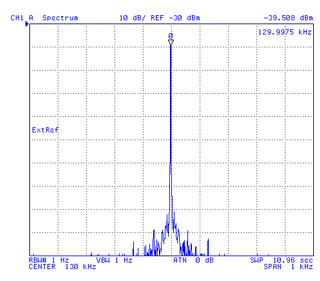
USM-159 Spectrum Plots
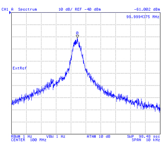
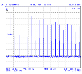
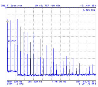
The CHK function was used with headphones by setting the frequency dial to a calibration point (triangle) and the Correction dial turned to get a zero beat. Then the function was switched to Operate. There are two plots for each of the bands, one showing the frequency of the calibration and the other a wide sweep showing the harmonics.
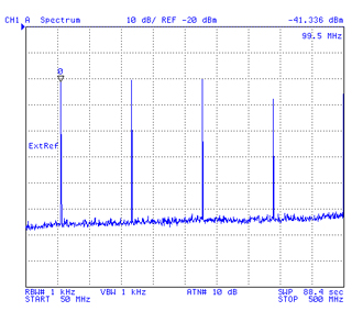
These plots were made with the frequency dial set at the same place for each band, but different places band to band. The harmonics are spaced closest together when the frequency is near the bottom of the range. As the frequency moves up the separation also increases.
On band 3 (65 - 1000 MHz) the calibration had no audio tone at 65 MHz, but did slightly higher, maybe needs a tweak? So used the calibration point at 100 MHz, but the audio tone was not clean but instead had a fuzzy sound. That's reflected in the broad noisy peak on the 100 MHz top plot below. Maybe there's something wrong with the band 3 oscillator?
0.125 - 2.5MHz
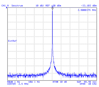
2.5 - 65 MHz
65 - 1000 MHz
The measured freq is 129.9975 v. 130 kHz
delta = 1.9E-8
measured freq 2.5000375
delta = 0.015 % (1.5E-4)
measured 99.9994375 (noisy)
delta = 5.6E-6
Error in marker frequency on wide display.
Correct in narrow span plot above.
Spectrum Analyzer limited to 500 Mhz max
so higher harmonics not shown
USM-159 Manuals
TM 11-6625-486-14&P Operator's, Organizational, Direct Support and General Support Maintenance Manual (Including Repair Parts and Special Tools) for
Frequency Meters AN/USM-159, AN/USM-159A, and AN/USM-`159B (NSN 6625-00-892-5360), 31 Oct 1975 w/Change 2 30 March 2006 216 pagesTB 9-6625-2120-35 Calibration Procedure for Frequency Meter, AN/USM-159, AN/USM-159A, AN/USM-159B
USM-159 Photos
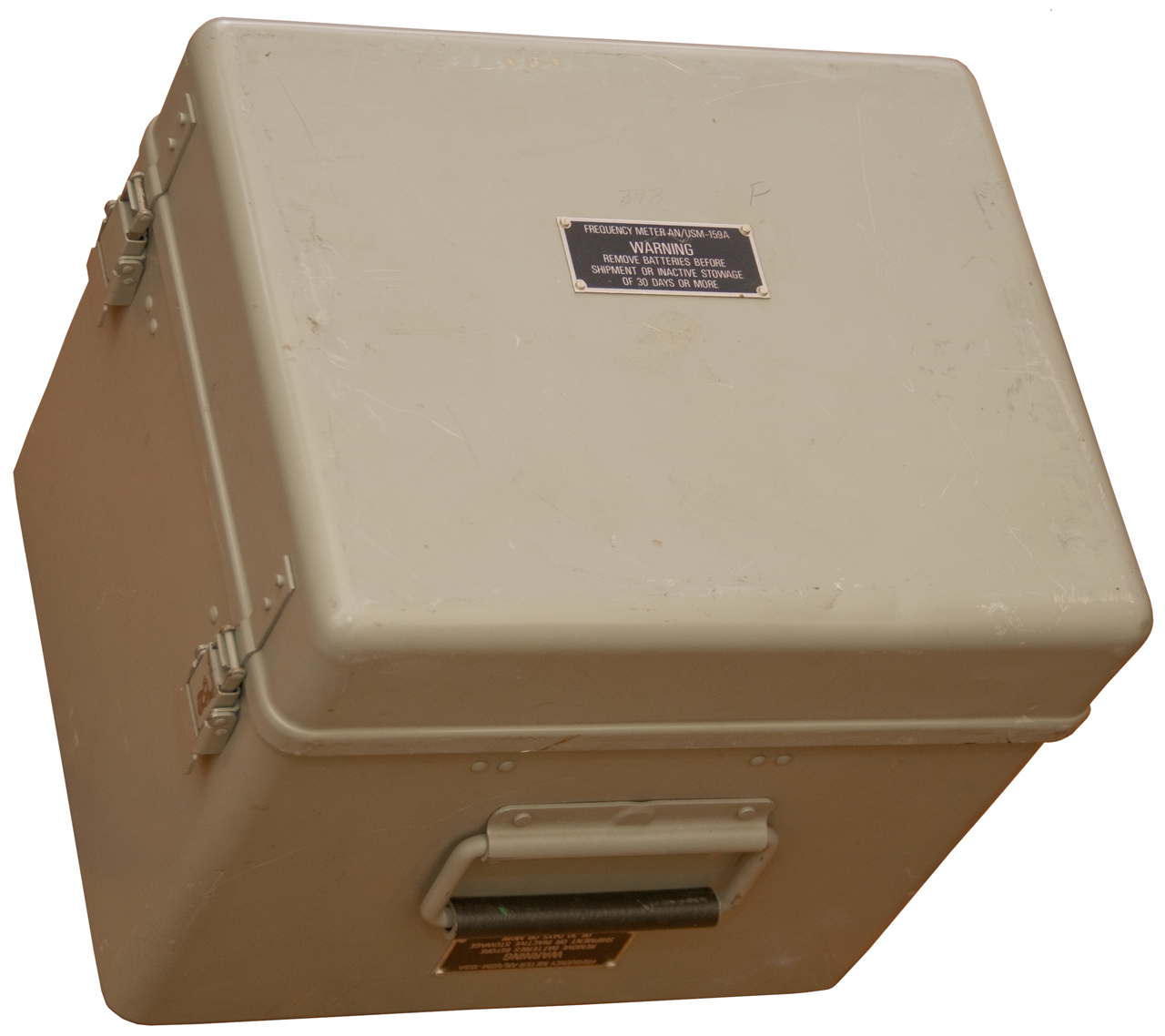
Fig 1 Carry case & Lid with accessories
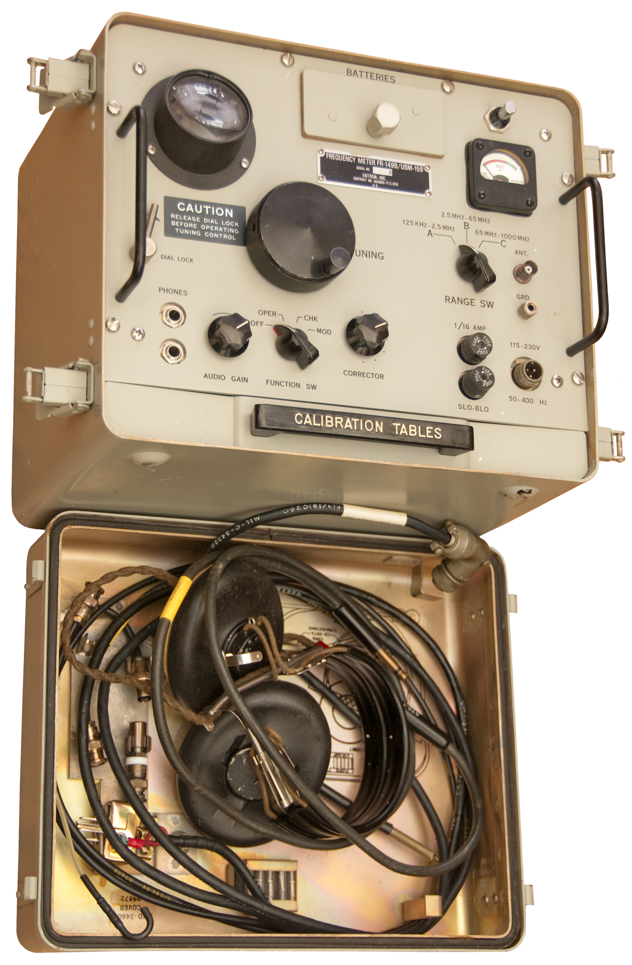
Fig 2 Open Carry Case
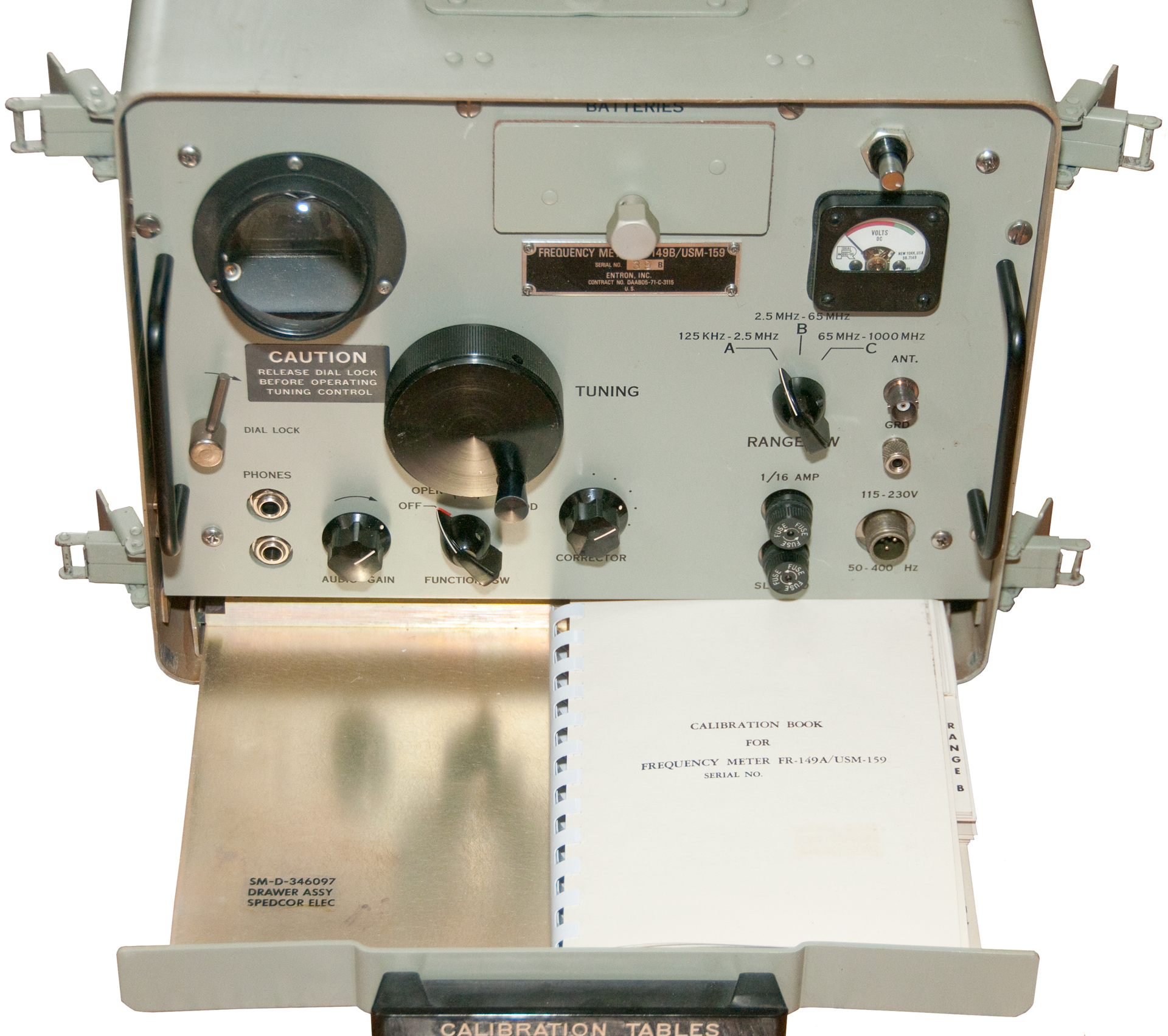
Fig 3 Front Panel w/Cal Book
Fig 4 Front panel in Operation.
H-216/U headphones (short 1/4"PJ-054R plug)
CD-307A 4' audio ext cord
CX-12005/USM-159 AC pwr cord
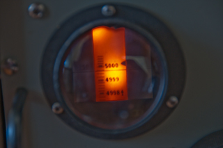
Fig 5 Closeup Film strip set near 5 .000 MHz
BC-221-B (early or late model?) Frequency Meter
The Signal Corps Western Electric BC-AL-230 (aka: BC-230) Transmitter, 3200 to 4000 kHz uses a tuning mechanism that's very similar to that used on the BC-221 & LM-18.
The BC-AR-430 SCR-283.
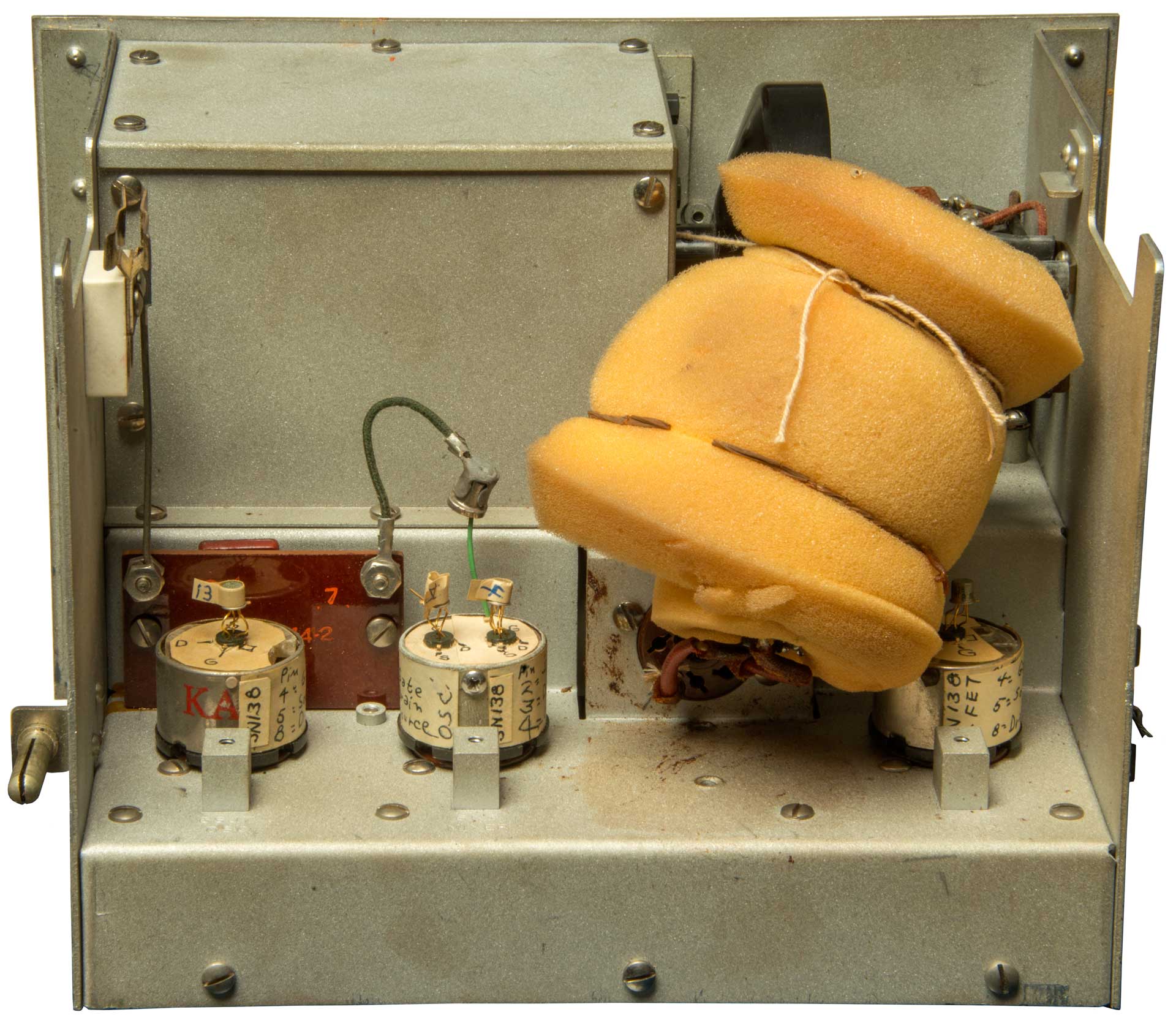
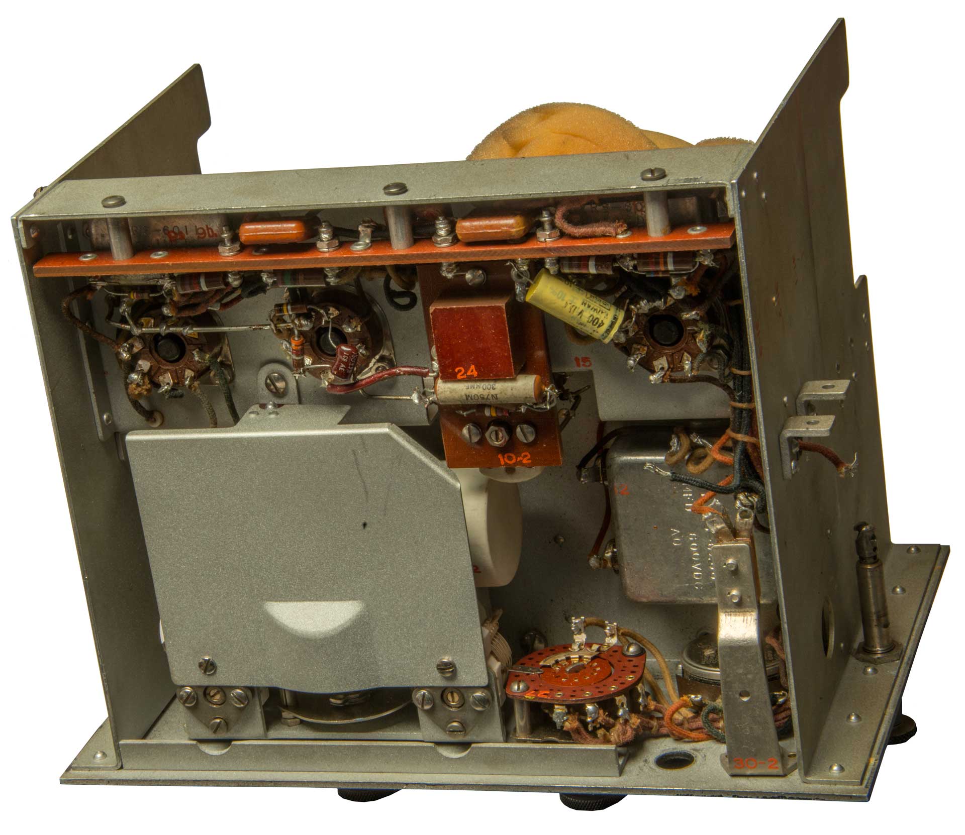
Surprise
It turns out that a prior owner has made some interesting modifications. See Fig 3 & Fig 4 below.
1. Three vacuum tubes have been replaced with solid state equivalents.
2. The crystal has been relocated in a foam blanket. Maybe for thermal stability and/or microphonic reduction?
Photos
Fig 1
Fig 2
Fig 3
Fig 4 What is the wire on the right?
LM 18 Crystal Calibrated
Frequency Indicating Equipment
LM-18 Photos
To remove chassis:
Remove 6 screws at left, top and right of front panel;
Remove 3 screws at back.
Slide front panel out of box.
Fig 1
Fig 2
Fig 3
Fig 4
Fig 5 MFP May - 1950

Fig 6

Fig 7

Fig 8
Fig 9 L101 (lo band) & L102 (hi band)
Mostly shielded.
LM 18 Calibration Book
At the bottom of each data page of the cal book in red are the crystal calibration frequencies printed in red. For the cases where the tabulated VFO frequency matches the crystal or one of it's harmonics there's also the dial setting printed in black. It took me a while to see this since on pages 8 and lower there are no red frequencies printed in the table.
For example at the bottom of page 7:
Crystal Check Point - 181.82, 363.64, 727.37, 1454.54 - 2150.1
Using the Low Band Equation gives 183.838 kHz, i.e. a couple of counts higher than the accurate 181.82 kHz
1,000 kHz / 181.82 = 5.4999 or 5.5 X, so VFO *11 mixed with Crystal *2
1,000 kHz / 363.64 = 2.74997 or 2.75X so VFO *11 mixes with Crystal *4
Front Cover
Instructions & pg 1
pages 13 & 14
page &
Rear Cover
DOD Form (was inside cal book)
Cardinal Dial Points
Dial
Book
Dial
Nominal
LF
Frequency
HF Frequency
0194.2 200 125 kHz
4405.9 4400 250 kHz
0385.7 400
2,000 kHz 4460.8 4400
4,000 kHz Low Band Equation
F (Hz) = (Dial-200) * 29.7619 (Hz/Div) + 125,000 Hz
High Band Equation
F (Hz) = (Dial-400) * 500 (Hz/Div) + 2,000,000 Hz
BC-221 & LC-18 Description
While called a frequency meter, it is not a frequency counter and it does not have a meter that indicates frequency, so, in my opinion not a frequency meter. The purpose was to set analog HF (125 kc to 20Mc) radio transmitters and receivers to a specific frequency.
To set the frequency of a receiver a CW signal at that frequency is generated in the test set and the receiver tuned to that frequency. To set the frequency of a transmitter, the Tx signal is picked up by a small antenna (E-field probe) and the transmitter adjusted so that a zero beat is heard in the test set headphones.
The test set contains a 1 MHz crystal oscillator that is designed to be rich in harmonics. These harmonics can be used to calibrate the VFO control dial at the nearest mega Hertz and so have a more accurate result.
The VFO has two ranges 125 to 250 kc and 2 to 4 Mc. The rest of the frequency range is covered by using harmonics of the two fundamental ranges.
Fund
2nd
4th
5th
8th
125 - 250 kHz
250 - 500
500 - 1,000
na
1,000 - 2000
2 - 4 MHz
4 - 8
8 - 16
10 - 20
na
LM-18 Labels
Model LM-18
Crystal Calibrated
Frequency Indicating Equipment
Supply: 110 V 1(phase) 60 cps Serial 12872 (maybe for the comboned Power Supply and Frequency Meter?)
For complete list of units see instruction book
Navy Department
Bureau of Aeronautics
---------------
Contractor
Loral electronics Corp.
New Your New York
Contract US No a(s)-9953
Type CBLC-74028
Hetrodyne Frequency Meter
Frequency Range: 125 to 20000 kc.
Input: 12/24 F 0.6/0.3 A DC & 180 - 475 V 5-20 mA DC
Serial 1477 (matches s/n on Calibration Book)
-----
A unit of Model LM-14 or LM-18 Radio Equipment
----
Navy Department - Bureau of Aeronautics
by contractor
Loral Electronics Corp.
New Your New York
Contract US No a(s)-9953


-221 Variants
From TM-300 with Supplement 6 February 1945:
Dash
Schematic
Switch
Cabinet
Power
Tubes
-A
1
Xtal Off
OnAl Batt
Clamp
Glass
-B
2
Off
Crystal
Operate
CheckAl Batt
Tray
Metal
-C
1
Xtal Off
Xtal OnAl Batt
ClampGlass
-D
1
Xtal Off
Xtal OnAl Batt
ClampGlass
-E
E
Off
Crystal
Operate
CheckAl Batt
ClampGlass
Loctal
-F
3
Xtal Off
Xtal OnAl Batt
ClampGlass
-J
3
Xtal Off
Xtal OnAl Batt
ClampGlass
-K
3
Xtal Off
Xtal OnAl Batt
ClampGlass
-L
3
Xtal Off
Xtal OnAl Batt
ClampGlass
-M
4
Het Osc
Xtal Check
Xtal OnlyAl Batt
ClampMetal
-N
5
Off
Crystal
Operate
CheckAl Batt
ClampMetal
-O
4
Off
Crystal
Operate
CheckAl Batt
ClampMetal
-P
6
Het Osc
Xtal Check
Xtal OnlyAl Batt
ClampMetal
-Q
2
Off
Crystal
Operate
CheckWood
Al
Batt
TrayMetal
-R
4
Het Osc
Xtal Check
Xtal OnlyAl Batt
ClampMetal
-T
6
Het Osc
Xtal Check
Xtal OnlyAl Batt
ClampMetal
-AA
5
Off
Crystal
Operate
CheckWood
AlFiber
Board
Metal
-AC
4
Het Osc
Xtal Check
Xtal OnlyWood Fiber
BoardMetal
-AE
7
Off
Crystal
Operate
CheckWood Fiber
BoardMetal
-AF
6
Het Osc
Xtal Check
Xtal OnlyWood Fiber
BoardMetal
-AG
7
Off
Crystal
Operate
CheckWood Fiber
BoardMetal
-AH
6
Het Osc
Xtal Check
Xtal OnlyWood Fiber
BoardMetal
-AJ
7
Mod Osc
Het Osc
Xtal Chk
Xtal OnlyWood Fiber
BoardMetal
-AK AK
Off
Warm-up
Crystal
Operate
Modulate
CheckWood Fiber
BoardMetal Frequency Meter BC-221-AK Repair, 1:03:37 -
bad caps (paper instead of mica), bad air var caps
bimetal strip rotates single turn Cu coil for temp stab.-AL
7
Mod Osc
Het Osc
Xtal Chk
Xtal OnlyWood Fiber
BoardMetal
LM Series are the Navy version Frequency Indicting Equipment
Model
Freq
Crystal
LM
195-400
2000-4000
1 Mhz
TS-323/UR
20 - 450 MHz
1 Mhz DC Power
Provided by batteries or an optional AC adapter that fits the space of the battery tray.
Filaments: 6V (4 each BA-23, 1.5V (No. 6) batteries) - 0.86 - 0.91 Amps (~3.6 Watts). Plugging in the headphones turns on the filaments -
Plate: 135V (6 each BA-2, 22.5V batteries) - 14.5 - 17 mA (21 Watts).
There are some cleaver temperature compensation devices that are used instead of putting the crystal in a temperature controlled oven. Ovens are not compatible with battery power. I expect all the capacitors that are in tuned circuits have very specific temperature coefficients. The -AK has a single turn copper coil (lowers inductance unlike ferrite which raises it) on a shaft where the rotation of what amounts to a variometer (variable inductance) is controlled by a Bimetallic coil (Wiki).
RA-133-B Power Supply
Fits into the battery tray space.
Switchable 115 or 230 VAC input.
6.3 VAC & 125 VDC regulated output.
Tubes
Glass
metal
Function
Base
VT-77
VT-116
6SJ7 or
6SJ7Y
VFO
Octal
6A7
VT-167
6K8
Xtal Osc
Octal VT-76
VT-116
6SJ7
Audio Amp
Octal
Manuals
TM 11-300 (Radio Nerds TM 11-300, 20 July 1944, Sup 6Feb1945)
Patents
looking for patents related to the Hetrodyne Frequency Meter.
There are many patents below relating to the harmonic type crystal reference oscillator and the associated mixer/detector.
1947182 is the overall patent for the Heterodyne Frequency Meter.
I expect there are patents for the Variable Frequency Oscillator (Wiki: VFO, Electronic Oscillator). Note that the frequency control is by a mechanical system of gears so requires a very linear tuning curve. Collins is known for this type of tuning. See for example the R-390A receiver (Wiki).
GR Model: LN Radio Freq. Oscillator Equip., Frequency Range: 15 to 25,000 kcs. (gr_model_ln.pdf) - has a band switch with 7 ranges, 4 tubes + PS,
GR 720 Hetrodyne Frequency Meter covers 10 to 3,000 MHz. VFO covers 100 to 200 MHz.
The 1941 GR model LR-1 Combined Hetrodyne Freq. Meter and Crystal Controlled Calibrator Equipment (lr1-man-4104.pdf) covered 160 kHz to 30 MHz, weight: 155 pounds, took 160 Watts from the 120 V AC mains, used 21 octal based vacuum tubes.
1579482 Variable air condenser, Jesse J Jorgensen, 1926-04-06, - adjustable insulating cones support plates, see 2282215 & 2913646
1673173 Crystal-calibrator apparatus, Robert H Worrall, Wired Radio Inc, 1928-06-12, -
1632369 Radio signaling system, Crossley Alfred, Wired Radio Inc, 1927-06-14, -
Crystal oscillator with a lot of harmonicas followed by a tank circuit to select the desired harmonic, then an amplifier that has grid keying for Morse Code operation.
1673200 Crystal-controlled calibrator, Raymond B Owens, Wired Radio Inc,1928-06-12, - coils 6 & 10 have low self capacity in order to get a harmonic rich output from the crystal oscillator.
1696933 Crystal calibrator harmonic selector and amplifier circuit, Robert H Worrall, Wired Radio Inc, 1929-01-01, - 1. provide a circuit arrangement for a crystal calibrator harmonic selector and amplifier wherein the particular harmonic which is being utilized may be readily determined.2. Another object of my invention is to provide a coupling system between the output circuit of the piezoelectric crystal controlled oscillator and a detector system of such character that the particular harmonic to which the circuit responds may be readily selected without the necessity of resorting to a wave or frequency meter.
1788219 Wave-meter circuit, Edwin L White, Federal Telegraph Co, 1931-01-06, -
Built-in 50 kHz comb generator.
1789912 Tuning device, Harold A Snow, Radio Frequency Labs, 1931-01-20, - gear drive with drum or tape behind window.
1828706 Oscillation generator and method, Frederick A Kolster, Kruesi Geoffrey Gottlieb, Federal Telegraph Co,1931-10-20, - ...capable of operation at extremely high radio frequencies, and which will oscillate at a relatively constant frequency.
1843415 Crystal controlled calibrator or transmitter, Crossley Alfred, Federal Telegraph Co, 1932-02-02, -
Fig 1 Shows "B" an R.F. Generator as a block. This would become the Variable Frequency Oscillator.
1866441 Universal crystal controlled calibrator, Robert H Worrall, Raymond B Owens, Wired Radio Inc, 1932-07-05, -
Tube (1) is harmonic rich crystal oscillator that has 3 frequencies depending on a special crystal with X (50 kcs), Y (500kcs) or "coupling" fundamental frequency chosen by switch 19. Tube (2) is a combined detector and amplifier
1884679 High-frequency oscillatory system, Olson John, Wired Radio Inc,1932-10-25, - works with Xtal or L-C circuit.
1893666 Temperature control system for electromechanical oscillators, Louis A Gebhard, Wired Radio Inc,1933-01-10, - used with piezo (quartz) crystals.
CH159805 Electrical device with an arrangement for controlling the frequency of a tube oscillator, Bell Telephone, App: 1931-07-17, Pub: 1933-01-31, - aimed at high stability for use with SSB receivers.
maybe the oscillator for the Heterodyne Frequency Meters.
Note the inductor is combined with resistance and has 3 terminals. This may apply to the USM-159, BC-221 & LM series Heterodyne Frequency Meters.
1933979 Oscillator circuit, Olson John, Wired Radio Inc,1933-11-07, - works with Xtal or L-C circuit.
1947182 Constant frequency apparatus, Philander H Betts, Bell Labs, 1934-02-13, -
This is the heart of the 3-tube Hetrodyne Frequency Meter.
1961783 Inductance coil, Roder Hans, GE, 1934-06-05, - temperature compensated
1984514 Constant temperature apparatus, Philander H Betts, Bell Labs,1934-12-18, -
2012497 Electrical system, Clapp James Kilton (Wiki), General Radio Co, 1935-08-27, - Crystal oscillator circuits
2014913 Circuit for precision control of master oscillators, Albert H Taylor, Wired Radio Inc,1935-09-17, - Master Oscillator - Power Amplifier (LC type)
2029358 Electromechanical vibrator, Clapp James Kilton (Wiki), General Radio Co,1936-02-04, - quartz crystal bar mounting - maybe 100 kHz?
2077544 Electric condenser, Behr Leo, Leeds and Northrup Co, 1937-04-20, - variable cap with glass beads supports
2119389 Frequency meter, Hunt Frederick Vinton, General Radio Co, 1938-05-31, - lissajous patterns on a CRT (Wiki)
2142999 Oscillation system, Craft Liva Morgan, Collins Radio Co, 1939-01-10, - crystal oscillator with harmonics
2159105 Oscillator for multiple wave band receivers, John D Reid, RCA, 1939-05-23, - probably aimed at combined AM broadcast band & Shortwave radios, would also work for HFM.
2164165 Electrical condenser, Karl F Rodgers, Bell Labs, 1939-06-27, -
While intended for use on multichannel telephone systems, it has the look and feel of the worm gear system used on the LM18 and BC-221 Hetrodyne Frequency Meters.
2181280 Electrical wave production, Ralph L Miller, Bell Labs, 1939-11-28, - output: 2 to 50 kHz audio tones. better than cold cathode tube method.
2228367 Frequency meter, Jr Royden C Sanders, RCA, 1941-01-14, - analog frequency meter for use with radar altimeters
2282215 Condenser, Frederick H Drake, Aircraft Radio Crop, App: 1939-04-11, W.W, II, Pub: 1942-05-05, - glass ball supports & variable trimmer caps - no mention of temperature
2307316 Frequency meter, Wolff Irving, RCA, App: 1941-02-13, W.W. II, Pub: 1943-01-05, - for use with radar altimeters
2337328 Electrical measuring circuit, Jarrett L Hathaway, RCA, App: 1941-12-30, W.W.II, Pub: 1943-12-21, - hetrodyne frequency meter - analog meter as output
2393856 Calibration system for radio receivers, Arthur A Collins (Wiki), Collins Radio Co, 1946-01-29, -
2423824 Inductive tuning, Robert B Beetham, Collins Radio Co, App: 1943-04-10, W.W. II, Pub: 1947-07-15, - linear tuning "This is accomplished by placing a relatively short fixed permeability core in operative association with one end of the coil and moving a longer tuning core in and out of the other end of the coll, the two cores being separated by a definite air space in their closest. position. This arrangement straightens the frequency-movement response curve, and lengthens the straight portion of such curve at the low frequency (high inductance) end. Moreover, the arrangement is such that a movable eddy current ring may be used to still further lengthen the straight portion of the tuning curve at the high frequency (low inductance) end of the tuning range. In addition, the short core provides an element which may be used for trimming or similar small variations of the inductance of the coil, and for temperature compensation purposes."
2465500 Multiband fixed frequency calibration panoramic radio receiver, Wallace Marcel, Horace G Miller, Panoramie Radio Corp, App: 1941-07-17, SECRET, Pub: 1949-03-29, -
2484763 Harmonic-frequency generator, Rudolf E Sturm, Hazeltine Research Inc, App: 1941-09-20, TOP SECRET, Pub: 1949-10-11, - stronger harmonics without added circuitry.
2490404 Stabilized oscillation generator, Warren H Bliss, RCA, 1949-12-06, - dials for X1, X10 & X100.
2510381 Frequency meter, Cushing Philbrook, Aircraft Radio Corp (Wiki: ARC), App: 1947-04-21, Pub: 1950-06-06, - uses an R-C oscillator, not a crystal; tube flip-flop drives analog meter circuit
2617035 Multiband oscillator, Janssen Johannes Mar Lodevicus, Ensing Lukas, Hartford National Bank and Trust, 1952-11-04, - have the feed of the VFO in the HFM. Includes scaling to equalize the frequency change per division.
2749515 Direct-reading frequency meter, Paul G Hansel, Servo Corp of America, 1956-06-05, -mechanical pulse counter
2913646 Electric condensers, Jr Atherton Noyes, Aircraft Radio Corp (ARC), 1959-11-17, - glass ball supports & temperature insensitivity
"The stator is adjusted by turning the screws 25 by means of an instrument inserted in the holes 29. Translational adjustment is obtained by turning both screws the same amount in the same direction. Rotational adjustment is obtained by turning one of the screws with respect to the other.
The two adjustments are made after the condenser has been completely assembled so that the correctness of each adjustment may be determined by electrical measurement. Each adjustment is made in such a way as to obtain minimum capacity for the section of the condenser being adjusted. This insures positioning the fixed plates accurately parallel to the movable plates and placing them in the middle of the spaces between pairs of the movable plates.
After this adjustment has been accurately made, a change in the temperature of the condenser has a minimum effect on the capacity of the condenser. Furthermore, wherever the balls may be seated in the slots, good mechanical stability is maintained regardless of minor in accuracies in the manufacture of the parts."


Related
Time & Frequency -
HP 5060A Cesium Beam Frequency Standard
HP5100 5110A Synthesizer Driver & 5100A Frequency Synthesizer
FTS4060 & Datum 4065B Cesium Time and Frequency Standard
HP 5216A 12.5 MHz Nixie Tube Electronic Counter
HP5342 Microwave Frequency Counter
HP5345 Counter
TandFTE Time & Frequency Test Equp:
Gibbs Crystal Oscillator
Stanford Research SC10 Crystal Oscillator
Stanford Research PRS10 Disiplined Rubudium Oscillator
HP 53132A Counter
Frequency Standard
Stanford Research SR620 Counter
HP 33120A Function ARB Generator
HP 8648A Signal Generator
Stanford Research DG535
HP 54501 Scope
References
Electric Radio Magazine (ER# 310 & ERE# 311) March & April 2015: The FR-149/USM-159 Heterodyne Frequency Meter, Part 1 & Part 2
Electronics magazine May 1944 - Automatic Calibrator for Frequency Meters by David Sunstein & Joseph Tellier (pdf page 108).
W4NPN - BC-221, LM & SCR Information -
LM-21 Heterodyne Frequency Meter -
CBLC-74028 Heterodyne Frequency Meter - List of models -
LM-13 Heterodyne Frequency Meter - schematic: 3 tubes (77, 6A7, 76), two series Neon bulbs for B+ stabilization + Mods for better performance
Frequency Measurement with the LM/BC-221, by Kenneth N. Sapp, W4AWY, QST 1965 Sep,
AAF Radio: SCR-AE-183 -
Solid State Tube Replacements:
References
Hearing Ref 2, SOLID STATE PRC-6's? AND SOLID STATING IN GENERAL,
eBay: "solid state" tube, SolidStateTubes;
Triode emulator - Part 2, Dimitri Danyuk (for solid state guitar amp),
73 May 1971 - "The Transistorized LM Freq Meter", (73-magazine-1971-05/05_May_1971.pdf) - Requires some changes to chassis components.
Electronics, Apr 10, 1972; Vacuum Tubes Yield Sockets to Hybrid JFET Devices, Bruce Burman -
Electrical Design News, Sept 14, 1966; Designing with FETS in Cascode,
The Western Electric Engineer, Jan. 1975; "Hybrid Integrated Networks", Holt et al.
KH6GRT - TUBESTERS by Skytec and FETRONS by Teledyne Semiconductor -
Patents
3531654 Solid state substitute for a dual triode electron tube, Robert L Eby, 1970-09-29, - form, fit & function replacement for 12AU7 dual triode.
3742261 Solid state vacuum tube replacement, E Schneider (Sunnyvale), B Burman (Cupertino), Teledyne Inc (Mountain View), 1973-06-26, - form, fit & function replacement for 6AK5 pentode but operated as triode.
3757245 Temperature compensated field effect transistor crystal oscillator, R Berger, Western Electric, 1973-09-04, - replaces prior art pentode vacuum tube, but needs temperature compensation that tube did not require. Maybe used in a Frequency Meter?
3767946 Junction field effect transistor device for replacing a pentode, R Berger, A Holt, Western Electric, 1973-10-23, - pentode including the screen grid.
3953808 Solid state amplifier, Charles W. Clark, Edwin G. Morton, Robert L. Voss, Western Electric, 1976-04-27, - improvement on 3767946 that works with inductor (transformer) load.
Links
PRC68, Alphanumeric Index of Web pages, Contact, Products for Sale
Page created 23May 2016