FTS 4060 Cesium Frequency Standard
Datum 4065B Time & Frequency Standard
© Brooke Clarke 2004 - 2020 FTS4060/S24
Cesium Frequency Std
Datum 4065B Time & Frequency Standard
Fast Test Method with SR620 Counter
4065B Frequency Offset
Box Rotated
Manual Project
Symmetricom Chip Scale Atomic Clock
Related
Links
Each of the three batteries is has four "X" 5 AH cells where each cell is a Cyclon cylindrical sealed lead acid cell. The 2.5 AH "D" cells were used in the O-1814 Rubidium Time & Frequency standard. The top of each battery is marked "bad" and a date of 10-2-01. The voltage across the pack is now 31.2 VDC but there probably is no current flowing if any one cell is bad, so some testing will be needed to see what the real problem is.
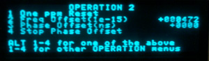
Unlike the FTS 4060 where you manually set the C-Field this one monitors and adjusts based on the following items as reported in the Status 5 menu:
Ramsey Error -10 S.B. <= 160 mv
Rabi-Ramsey Error 0 S.B. <= 40 mv
Zeeman Error -15 S.B. <= 160 mv
Rabi-Zeeman Error -4 S.B. <= 160 mv
Ramsey Confidence +3 S.B. <= 160 mv
 7
April 2008
7
April 2008
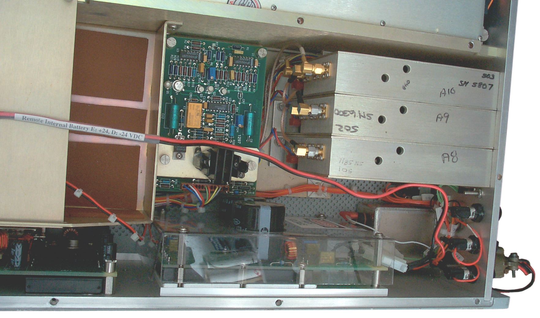
The Red-Black Siamese cable has male 1/4" Faston connectors that match those on the batteries and so plug into the internal battery wiring connectors. The white label says:
Remote Internal Battery D: -24, E: +24 VDC.
The Plug in the lower right of the photo connects D to black and E to Red. The other end of the cable has female 1/4" Faston connectors to plug into the battery. This solves the two major objections to an internal battery, i.e:
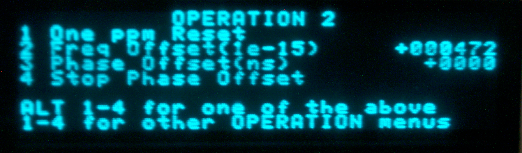
After plotting for the time interval between the 4065B and GPS from 5 May to 7 May (4065plot9.pdf) and finding a straight line with a slope of 472E-15 the Frequency Offset was changed from +000000 to +000472 (a 50-50 gamble that the sign should be +).
A new plot was started 7 May after the change and for the first couple of days seemed to have worked. By starting a new plot I mean that constants were subtracted from the time interval so it starts at 0.0 and the starting second count starts at 0.0. This way is the plot is a straight line it can be forced to go through (0,0).
By May 10 at 9:50 am it looked like the frequency offset had worked. The data (plot10a.pdf)was in a box about +/- 10 ns high after 2 3/4 days (3E-13) but more time needed for good data.
Then the points started a climb. By 14 May (4 days later) the data between May 10 and 14 looks again like a nice straight line (plot10.pdf)with a slope of about 472E-15. BUT the frequency offset is still set at +000472. (4065BvsGPSp10b.pdf). The 4E-13 number floating on the plot is the slope after one day. Just put it there so I could remember what it was. Excel recomputes the slope as each new data point is added.
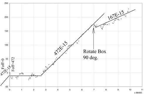
Before this plot was started the frequency offset was stable at 472 (parts in E-15) and the 4065 Frequency Offset was set to +472.
For the first couple of days it looked like that change was working and the frequency offset was near zero.
But then the frequency offset returned to +472 (this with the Frequency Offset dialed to 472) and that continued for over four days when I turned the 4065 box 90 degrees clockwise (just prior to the day 7 grid line). That made a big change and now (May 17 2008) the slope is more like 167 (parts in E-15).
It may be that the Earth's magnetic field is having an influence or maybe just the mechanical shock has the influence.
Any thoughts what's going on? Contact Brooke
Datum 4065B Time & Frequency Standard
Fast Test Method with SR620 Counter
4065B Frequency Offset
Box Rotated
Manual Project
Symmetricom Chip Scale Atomic Clock
Related
Links
4065B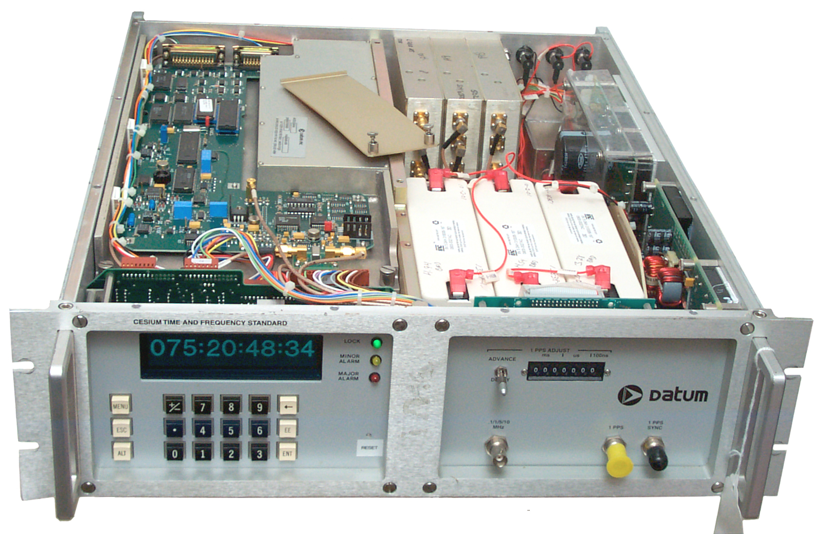 |
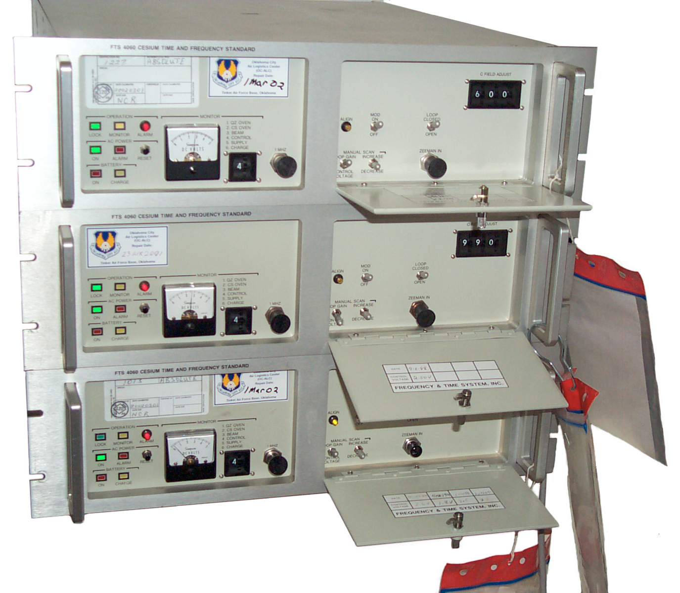
| Datum 4065B Cesium Time
& Frequency Standard top off showing three 8 Volt
batteries. On the right the toggle switch (advance/retard and the 7 thumbwheel switches control the movable 1 PPS output in 100 ns steps. The BNC just below the toggle is the programmable frequency TTL square wave output (.1/1/5/10 MHz). The yellow cap is on the 1 PPS master output. The black cap is on the 1 PPS sync input BNC. |
 |
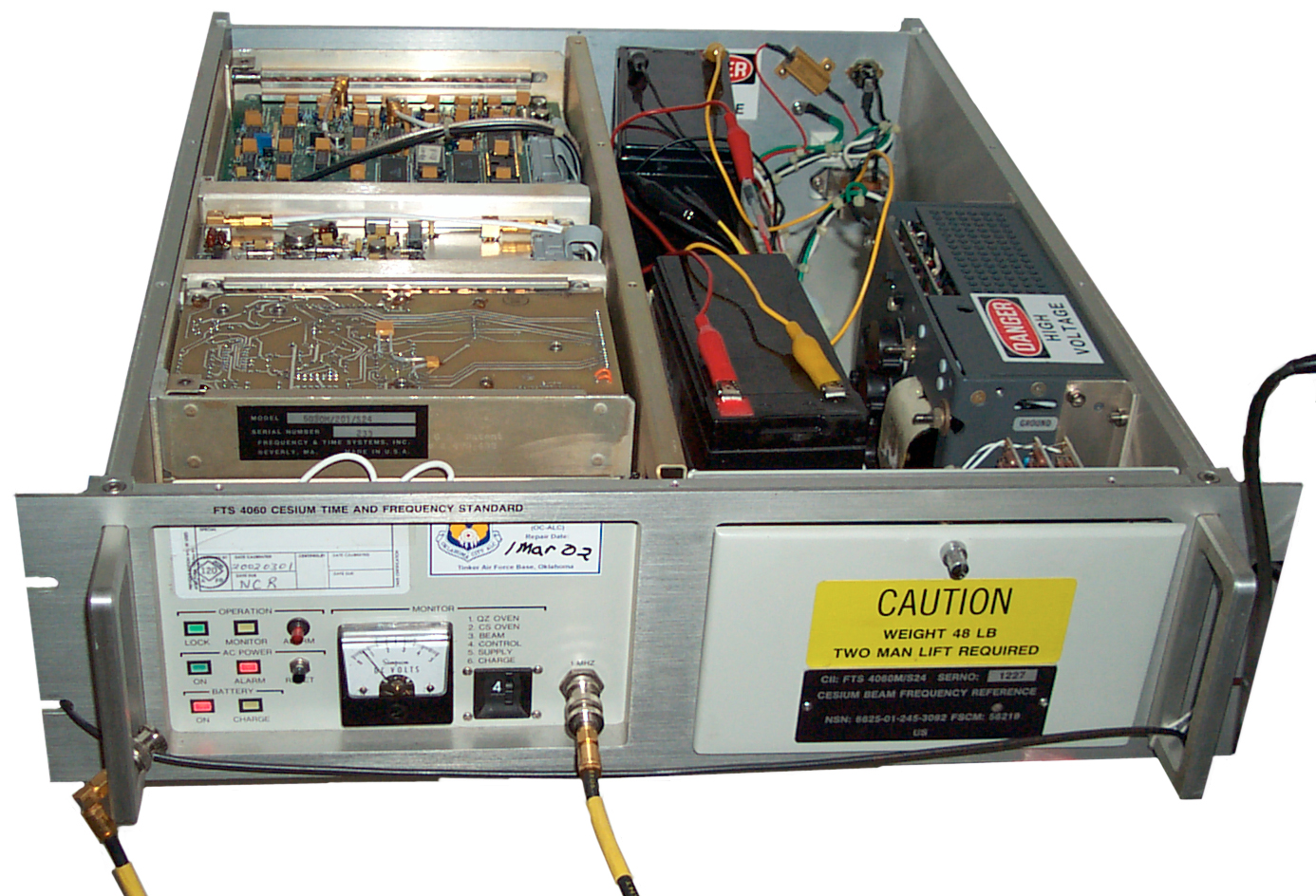
| Datum
4065B Rear Panel Two 7AH Gel Cell 12 Volt Batteries connected while working on the three 8V 5 AH batteries. Just to the right of the line cord jack is a toggle switch which when turned down shuts down all of the unit except for the ion pump. A much better solution to storage than circuit mods. The field of type-N connectors has 3 ea 10 MHz out, 3 ea 5 MHz out and 3 ea 1 MHz out all 1 Vrms, 50 Ohms. The BNC above the DB-9 is the alarm status and the DB-9 is alarm info. The DB-25 is a serial connector for data I/O. This box does not have the optional telecom outputs. The far top right BNC is the master pulse out. Below it is the adjustable offset 1 PPS out. |
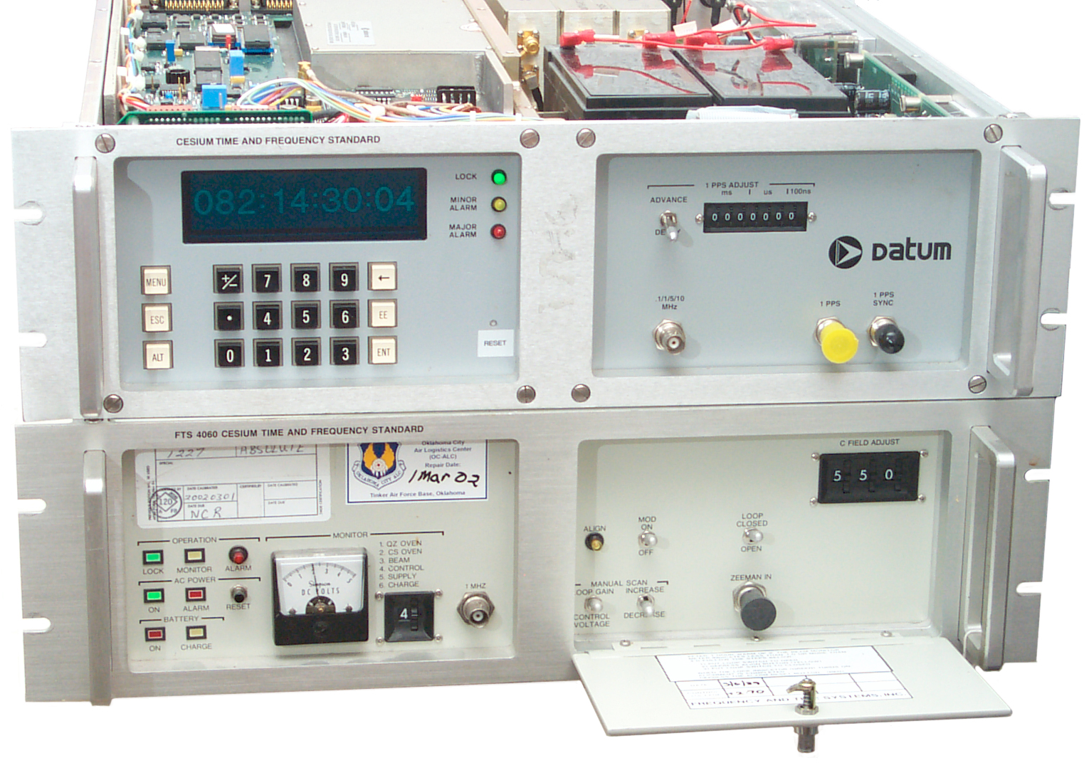 |
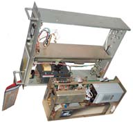
| Getting ready to
compare them. You can see the family
resemblance. Note both units are locked and
operational. The 4060 is s/n 1227 and should be fairly close to on frequency. |
Fast High Precision Set-up of SR 620 Counter
This idea is from the PRS10
Rubidium Frequency standard manual appendix B.
This display should be within 0.1 Hz of 10 MHz
MODE to TIME
SOURCE of Start to A
GATE/ARM to +TIME and EXT
SAMPLE SIZE to 1000 (1 & 103)
Now each second there will be a display of 1,000 averaged readings. This brings the 620 precision down to 1 ps.
Input Connections
- 10 MHz Reference to BNC-T on rear panel 10 MHz Input then to front panel "A" start input
- 10 MHz DUT to front panel "B" stop input
- Front panel 1 kHz TTL REF OUT to front panel EXT Gate input.
Input Setups
- CONFIG - press SET to select cAL and press SELECT to choose "cLoc SourcE", use arrow keys to set rEAr.
- in the Gate field: select POS, TERM = 50 Ohms and LEVEL= +1.0 Volts
- for sine wave 10 MHz inputs set the A and B input
fields to: AC, 50 Ohms, Level full CCW, + Slope.
Coarse Check
MODE to FREQ, SOURCE to B, GATE/ARM to 1 second and SAMPLE SIZE to 1 then hold START down for a few seconds, DISPLAY to MEAN.This display should be within 0.1 Hz of 10 MHz
Fine Frequency Measurement
This will show 1E12 in one second.MODE to TIME
SOURCE of Start to A
GATE/ARM to +TIME and EXT
SAMPLE SIZE to 1000 (1 & 103)
Now each second there will be a display of 1,000 averaged readings. This brings the 620 precision down to 1 ps.
Datum 4065B Cesium Time & Frequency Standard
Background
The FTS4060/S24 is really a frequency standard and I've always wanted an excellent time standard.Condition
This unit came from an eBay ad showing a Major alarm and not locked. But when powered up it locked in about 10 minutes and after connecting the removed and taped battery wire and waiting an additional 10 minutes the charge fault could be cleared.Each of the three batteries is has four "X" 5 AH cells where each cell is a Cyclon cylindrical sealed lead acid cell. The 2.5 AH "D" cells were used in the O-1814 Rubidium Time & Frequency standard. The top of each battery is marked "bad" and a date of 10-2-01. The voltage across the pack is now 31.2 VDC but there probably is no current flowing if any one cell is bad, so some testing will be needed to see what the real problem is.
Theory of Operation
This is a modern Cesium standard that uses control loops so that it's frequency is correct, i.e. the C-field adjustment is automatic not manual like the 4060.Unlike the FTS 4060 where you manually set the C-Field this one monitors and adjusts based on the following items as reported in the Status 5 menu:
Ramsey Error -10 S.B. <= 160 mv
Rabi-Ramsey Error 0 S.B. <= 40 mv
Zeeman Error -15 S.B. <= 160 mv
Rabi-Zeeman Error -4 S.B. <= 160 mv
Ramsey Confidence +3 S.B. <= 160 mv
Power Supply
The AC mains power a 31 VDC supply that's diode ORed with the internal battery and the external DC supply. The internal supply is a 24 Volt lead acid battery, 12 cells of Cyclon "X" size cylindrical sealed pure lead acid. There are a couple of major problems with this:- The temperature inside the case is always warm to almost hot. That degrades the life of the lead acid battery by an order of magnitude.
- If there's any venting, like happened with the Gibbs double oven crystal oscillator, the fumes and heat make a good combination to etch the traces right off printed circuit boards.
 7
April 2008
7
April 2008The Red-Black Siamese cable has male 1/4" Faston connectors that match those on the batteries and so plug into the internal battery wiring connectors. The white label says:
Remote Internal Battery D: -24, E: +24 VDC.
The Plug in the lower right of the photo connects D to black and E to Red. The other end of the cable has female 1/4" Faston connectors to plug into the battery. This solves the two major objections to an internal battery, i.e:
- If battery vents acid fumes they will not destroy the expensive circuitry
- The battery will last 3 to 10 times longer when running at room temperature
4065B Frequency Offset
On the FTS4065 the C-Field adjustment is made by the internal microprocessor and there is a seperate Frequency Offset adjustment.After plotting for the time interval between the 4065B and GPS from 5 May to 7 May (4065plot9.pdf) and finding a straight line with a slope of 472E-15 the Frequency Offset was changed from +000000 to +000472 (a 50-50 gamble that the sign should be +).
A new plot was started 7 May after the change and for the first couple of days seemed to have worked. By starting a new plot I mean that constants were subtracted from the time interval so it starts at 0.0 and the starting second count starts at 0.0. This way is the plot is a straight line it can be forced to go through (0,0).
By May 10 at 9:50 am it looked like the frequency offset had worked. The data (plot10a.pdf)was in a box about +/- 10 ns high after 2 3/4 days (3E-13) but more time needed for good data.
Then the points started a climb. By 14 May (4 days later) the data between May 10 and 14 looks again like a nice straight line (plot10.pdf)with a slope of about 472E-15. BUT the frequency offset is still set at +000472. (4065BvsGPSp10b.pdf). The 4E-13 number floating on the plot is the slope after one day. Just put it there so I could remember what it was. Excel recomputes the slope as each new data point is added.
Box Rotated
The 4065 box was rotated 90 degrees and it did make a good sized change.
Before this plot was started the frequency offset was stable at 472 (parts in E-15) and the 4065 Frequency Offset was set to +472.
For the first couple of days it looked like that change was working and the frequency offset was near zero.
But then the frequency offset returned to +472 (this with the Frequency Offset dialed to 472) and that continued for over four days when I turned the 4065 box 90 degrees clockwise (just prior to the day 7 grid line). That made a big change and now (May 17 2008) the slope is more like 167 (parts in E-15).
It may be that the Earth's magnetic field is having an influence or maybe just the mechanical shock has the influence.
Any thoughts what's going on? Contact Brooke
FTS4060/S24
 |
 |
 |
Background
Model Numbers & Options
Operation
Monitor Voltages
Setting C Field
GPS
LORAN-C
Zeeman Resonance
Standby Power
Construction
Patents
5030 Assembly
Manual Control Voltage & Loop Gain Setting
Accessory
Data Request
Government Liquidation Warning
Manual Project
 Today, 15 June 2006, thre was a scheduled
power outage whicl PG&E replaced a power pole. Since
I still have not got the Austron 1290 Back Up power supply
operational, I juse connected a couple of 12 Volt 7 AH gel
cell batteries in series with a SB360 Schottky diode.
Using the male plug from a PC hard drive power supply "Y"
cable with the pins reinstalled so that black goes to black
(ground) and red goes to +30 and Yellow goes to orange (+5)
and with the diode cathode to the 4060 + 30 volt line the
batteries held up the 4060 for the 3 hours the mains power was
down. Now I have removed the batteries and a charging
them manually with a bench supply.
Today, 15 June 2006, thre was a scheduled
power outage whicl PG&E replaced a power pole. Since
I still have not got the Austron 1290 Back Up power supply
operational, I juse connected a couple of 12 Volt 7 AH gel
cell batteries in series with a SB360 Schottky diode.
Using the male plug from a PC hard drive power supply "Y"
cable with the pins reinstalled so that black goes to black
(ground) and red goes to +30 and Yellow goes to orange (+5)
and with the diode cathode to the 4060 + 30 volt line the
batteries held up the 4060 for the 3 hours the mains power was
down. Now I have removed the batteries and a charging
them manually with a bench supply.
The 12V 7 AH lead acid batteries are 3.75" from the bottom to the top of the metal terminals. The distance from the bottom of the battery shelf to the bottom of the lid is about 3.75", so it would be a bad idea to try and close the lid with the batteries inside. And there's an even more compelling reason to NOT put lead acid batteries in the same box as electronics. And that's because acid fumes from the lead acid battery will literally eat the traces off the printed circuit boards. So it's best if the batteries are out of the 4060.
It took about 2.7 AH to charge one of the 12 V 7 AH batteries and the power outage was about 2.7 hours, so the FTS4060 is pulling about 1 Amp.
But the 7 AH rating is for a 20 hour discharge (350 ma) so the battery will not last 7 hours at 1 amp. I think the terminal voltage at the end of the power outage was about 23.49 volts or 11.75 volts per battery which is discharged. Maybe 2.7 AH is the capacity at 1 amp?
After AC power is restored the Power On Green and the red Powere Alarm are both on (press the reset button to clear the red alarm LED).
The green lock LED is still on. No battery LEDs are on. (remember the /S24 has no battery option.)
 So now I have made up a simple 12 Volt
battery checker that's just a number 1156 car tail light
bulb soldered to a clip lead that was cut in half.
This pulls a couple of amps to light brightly and with only
1 amp will take some seconds to light dimly. This
works much better than the Radio Shack 22-080 battery tester
that shows a dead battery as good.
So now I have made up a simple 12 Volt
battery checker that's just a number 1156 car tail light
bulb soldered to a clip lead that was cut in half.
This pulls a couple of amps to light brightly and with only
1 amp will take some seconds to light dimly. This
works much better than the Radio Shack 22-080 battery tester
that shows a dead battery as good.
Note that the very common 12 V 7 AH batteries come with both 1/4" (0.250") and 3/16" (0.187) quick connect type terminals. On the batteries I got some are 1/4" and some are 3/16". So you need to check each battery, even though at a quick glance they look the same.
Chicago Miniature CMD series LED's.
Red CMD57124A
Yellow CMD 53124A
Green CMD54124A
4499433 Autolock for resonators for frequency standards Feb 12, 1985 Class 331/3; 331/94.1
5714910 Methods and apparatus for digital frequency generation in atomic frequency standards February 3, 1998 331/3; 331/94.1
5656189 Heater controller for atomic frequency standards August 12, 1997 219/499; 219/210; 219/501; 219/505; 330/289; 331/1R; 331/69
5627497 Resonator package for atomic frequency standard May 6, 1997 331/94.1; 331/3
4862101 System for producing spectrally pure optical pumping light August 29, 1989 359/345; 359/886
4588969 Adjustable crystal oscillator with acceleration compensation May 13, 1986 331/156; 331/175; 331/177V
4586006 Crystal oscillator assembly April 29, 1986 331/69; 219/210; 331/70; 331/158
5030 Assembly
Model Numbers & Options
Operation
Monitor Voltages
Setting C Field
GPS
LORAN-C
Zeeman Resonance
Standby Power
Construction
Patents
5030 Assembly
Manual Control Voltage & Loop Gain Setting
Accessory
Data Request
Government Liquidation Warning
Manual Project
Background
A common misconception (and one
that I had until working with a Cesium standard) is that the
timing is perfect. This is not the case. A Cesium
standard wanders around the nominal frequency, but may not
drift like a crystal oscillator. A couple of terms will
help when working with this concept.
Offset - is a measure of how close to the desired frequency an oscillator is running. For example an oscillator that's supposed to be at exactly 10 MHz is off by 0.0001 Hz has an offset of 1E-11. The offset is only valid at the instant when it was measured. It's measure a of how well someone set the frequency not so much about oscillator quality. Since this is something that's under the user's control a lot of time and effort go into minimizing the offset. It's common practice when setting the frequency of a lab grade crystal oscillator to set it right at the edge of the system spec, but on the side where aging will move the frequency so it at first gets better, then it's perfect, then it moves to the other side of the spec. In order to do this the aging rate (i.e. stability) needs to be known.
Note that a Cesium standard may not be set to have a zero offset, but rather most end up with an offset on the order of parts in E13 or E14. The offset is known and can be backed out of measurements on other time standards. But if the Cesium standard will be driving a clock or say a transmitter, the setting the offset to the lowest possible value is important. The key thing is that there is no aging, i.e. a time interval plot vs. GPS will be a straight line whereas a crystal or Rubidium oscillator will have a parabolic plot.
Stability - Stability is the money spec. a measure of how well the frequency stays the same. A perfect oscillator would not change frequency with time, power input, temperature, etc., but you can't get that one. The measure of how the frequency changes with running time is called aging. The specification on the HP (Agilent) 5071A Cesium standard ($50k) is less than 1E-14 per day. . That's to say that if it was set with a zero offset at noon today, by tomorrow noon it might by off frequency by 1E-14.
The plot at the bottom of web page http://www.niceties.com/utcdwh.html (650 days of data) shows what might be a random walk of around plus and minus 100 ns for an HP 5071A.
My s/n 1227 is running at abut -1.4E-14 per day. It would be a tad out of spec for the HP 5071A. Cesium sources are NOT supposed to have aging ike this.
Cesium standards are a step
better than Rubidium standards and are the basis of the
definition of a second. But that does not mean they are
"perfect".
These are the S24 option that has a 1 MHz front panel output, NSN 6625-01-245-3092. The official definition of a second of time is exactly 9,192,631,770 oscillations of a Cesium atom between the F3 and F4 states.
These were purchased from Government Liquidation with a condition code of "A1" which should mean that they are new. Here are some dates:
These are the S24 option that has a 1 MHz front panel output, NSN 6625-01-245-3092. The official definition of a second of time is exactly 9,192,631,770 oscillations of a Cesium atom between the F3 and F4 states.
First Generation
The HP
5060 was probably the first commercial Cesium
standard. It was all analog, no microcontrollers
then. HP took over the Varian line of Cesium
standards. Then when HP and Agilent split, Agilent
kept the Time and Frequency instruments and HP then became a
computer and imaging company.
Second Generation
The FTS4060 I would call a
second generation Cesium standard because it has a micro
processor that replaces a lot of analog circuitry and is
much easier to use. There is a manual C field
adjustment that needs to be set where the coarse thumb wheel
is 1E-12 per tick and the fine wheel is maybe 1E-14 per
tick.
Third Generation
These standards have a built
in C field setting system that uses the Zeeman effect.
They turn on at a much higher level of accuracy than prior
generations. The Agilent
5071A Primary Frequency Standard ,
Symmetricom 4065C, and others,
These were purchased from Government Liquidation with a condition code of "A1" which should mean that they are new. Here are some dates:
s/n |
First
control voltage date on Lid |
Front
Panel OC-ALC cal date |
| 1013 |
1/27/88 |
1
Mar 02 |
| 1033 |
7/1/88 |
23
Apr 01 |
| 1227 |
3/6/89 |
1
Mar 02 |
Possible meaning: The first
control voltage measurement was done at the factory as part of
the final inspection and so is close to the ship date.
These dates and the serial numbers are in the same
order. The front panel date may be when the units were
tested prior to being put up for auction. These dates
seem to be over 2 years prior to the auction date which may be
due to how fast the government surpluses them. Note that
it's about 14 years from the final test date to the surplus
date. So maybe there is some number of storage years
after which these units are surplused, say 15 years.
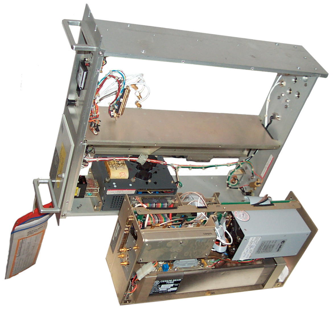
s/n 1013 was shipped outside it's carton and failed to lock when received. Opening the bottom of s/n 1013 shows the Cesium Beam tube, Brick power supply, and fancy 10 MHz crystal oscillator plus other components. Behind the Cs tube is paper work indicating it was replaced in 1996. There must be some reason that s/n 1013 is not working, need a manual to find it. In the left photo at the top of this page notice that the green "LOCK" light is on for the top two standards (1033 & 1227) and off on the bottom (1013) one.
s/n 1013 was shipped outside it's carton and failed to lock when received. Opening the bottom of s/n 1013 shows the Cesium Beam tube, Brick power supply, and fancy 10 MHz crystal oscillator plus other components. Behind the Cs tube is paper work indicating it was replaced in 1996. There must be some reason that s/n 1013 is not working, need a manual to find it. In the left photo at the top of this page notice that the green "LOCK" light is on for the top two standards (1033 & 1227) and off on the bottom (1013) one.
Model Numbers & Options
The normal FTS4060 comes in with
either a 10 MHz optimized output (/201) or a 5 MHz optimized
output (/101).
The /S24 option was a special unit made for the U.S. military and has only a 1 Mhz output on the front and rear panels and does not have other frequencies as outputs and does not have the 1 PPS output. It does not have the internal or external DC supply options. It's a stripped down model.
All of my units (s/n 1013, 1033, 1227 have the SMA-f connector on the A5 Distribution Amplifier Assembly, but not all /S24 units have this connector. It's the 10 MHz output at about 4.4 V Pk-Pk.
My s/n 1013 has a rear panel with a number of plugs like it was the same rear panel used for a full featured 4060, but s/n 1227 has a solid rear panel with no plugs, so in order to install the 10 MHz port I moved the alarm connector to the inside of the box and replaced it with the 10 MHz output.
Note that some FTS 4060 use a 5 MHz OCXO and others use a 10 MHz OCXO.
Option numbers
061 - 1 MHz and 100 kHz RF outputs
116 - Time-of-Day Display and 1 PPS Advance/Delay
117 - 1 PPS Advance/Delay
010 - Internal Battery and Charger
015 - External Standby Battery Supply
013 - Chassis Rack Slides
The /S24 option was a special unit made for the U.S. military and has only a 1 Mhz output on the front and rear panels and does not have other frequencies as outputs and does not have the 1 PPS output. It does not have the internal or external DC supply options. It's a stripped down model.
All of my units (s/n 1013, 1033, 1227 have the SMA-f connector on the A5 Distribution Amplifier Assembly, but not all /S24 units have this connector. It's the 10 MHz output at about 4.4 V Pk-Pk.
My s/n 1013 has a rear panel with a number of plugs like it was the same rear panel used for a full featured 4060, but s/n 1227 has a solid rear panel with no plugs, so in order to install the 10 MHz port I moved the alarm connector to the inside of the box and replaced it with the 10 MHz output.
Note that some FTS 4060 use a 5 MHz OCXO and others use a 10 MHz OCXO.
Option numbers
061 - 1 MHz and 100 kHz RF outputs116 - Time-of-Day Display and 1 PPS Advance/Delay
117 - 1 PPS Advance/Delay
010 - Internal Battery and Charger
015 - External Standby Battery Supply
013 - Chassis Rack Slides
Operation
Just plug in the line cord, set
the Mod switch to ON and the LOOP switch to CLOSED.
After something like 10 minutes to 30 minutes the green LOCK
light will turn on and the ALIGN pushbutton-lamp will turn
off.
You can manually press the Red Operation Alarm Light/Switch to turn it off.
Pressing the AC Power Reset switch will turn off the red Alarm light.
Pressing the Align Light/Switch may turn it off or initiate a new align sequence.
Near the brick power supply on the top side there's a Molex type connector with Red, Black and Orange wires. The connector is the same 4 terminal connector as used for hard drives in PC computers. To get a mating connector buy a "Y" PC power supply cable. You can tease out the male pins using a jeweler's screwdriver if you don't have the extraction tool ( a hollow tube that fits over the male pin). The reassemble with the black wire going to the black ground wire in the FTS4060, Red to the +30 wire and yellow going to the orange +5 volt wire. This makes for an easy way to connect both an external DC backup supply, like the Austron 1290A and also to supply 5 volts for a 1 PPS divider.
It seems that the scale factor for the /S24 using is 1E-13 per count NOT the 2E-14 in the normal FTS4060 manual.
9 Jan 2005 - Plot -
10 Jan 2005 - Plot of nano seconds of Time Interval vs seconds of running time for s/n 1013 - 5.9E-12?
12 Jan 2005 - Plot - Between 124,920 and 169,680 (12.4 hours) the 1 PPS input to the PRS10 was removed and when reconnected caused a negative swing that lasted until 248,400 seconds. But it appears that a C-Field setting of 913 is pretty close to correct. The drift is in the e-13 ot E-14 area.
18 Jan 2005 - Plot of s/n1013 vs. s/n 1227, 1227 vs GPS & 1013 vs GPS, now using s/n 1227 as 10 MHz ref for SR 620 counter.
s/n 1227 has it's C Field set at 600 as received from Govt Liq. and it appears to be moving at -3.6E-12. s/n 1013 seems to be moving at 5E-10 more like an OCXO than a Cesium, but the Lock LED is on and the beam current peaks as it should. What wrong?
1 Feb 2005 - s/n 1227 - I tried to use the time interval between GPS and the 1 Mhz output to set the C Field by getting the offset and then dialing in the correction (it looked like the three thumb wheels were 1E-12, 1E-13 and 1E-14), but the resulting slope after a few days of observation seemed to overshoot. A better way would be to use a binary search where at each attempt you would half the error. I think I have the setting to within a single count on the finest wheel, but it'll take some days to see.
10 Feb 2005 - s.n 1227 - Still have C field at 544. The 10 day plot shows GPS wandering within a 150 ns range so the poorest stability might be 1.7E-13, but an average would be more like parts in E-14.
10 Feb 2005 - Enabled Ionospheric correction in GPS receiver and the delta time jumped up to the 500 ns range, so this may account for the 100 or or ns variation the last 10 days. More time will tell.
11 Feb 2005 - changed GPS to track 4 highest satellites and changed elevation mask to 30 degrees.
28 Feb 2005 - The C field
has been at 570 for about 9 days and on average there
does not appear to be any drift, but it's difficult to tell.
2 March 2005 - To improve the stability of the GPS 1 PPS I increased the elevation mask again, this time from 30 degrees to 50 degrees. It has made a big improvement. The standard deviation after 1,000 seconds worth of 1 PPS averaging is now in the 30 ns area where before it was in the 200 ns area. During 3 days of observation there never was a time when there were no satellites above 50 degrees. Since I'm running the GPS receiver in the timing mode (known antenna position) only one satellite is needed for a timing solution.
8 March 2005 - C filed at 565 - After the problem with the 4060 going crazy after a beam current centering. Needed to cycle power to get good operation.
13 March 2005 - Yesterday the counter got unplugged, but neigher the FTS4060 nor the Austron 2100T were unplugged. Both of these instruments have warning LEDs that would indicate a loss of mains power, but the FTS-4060 output frequency became more unstable after this event. This morning I unplugged the FTS4060 for 10 seconds and restarted it. After that the standard deviation on the time interval improved from over 300 ns to more like 30 ns. Maybe there are some power supply caps that need replacing or more caps need to be added?
Also the amount of averaging on the GPS 1 PPS needs to be increased. At 1,000 averages the best stability that can be seen in one day is about
(3 * 35 ns * 2) / (SQRT(1,000) * 86400) = 7.6E-14, but by going to 5,000 seconds the system improves to 3.4E-14. So starting a new plot.
15 April 2005 - Switched to an SynPaQ/III with Motorola M12+T GPS receiver. This unit has 3 to 4 times less variation than the old 8 channel UT+ GPS receiver. But there appears to be a parabolic change in the plot over the past 5 weeks that I don't understand. The C filed has been at 568 since 20 March 2005.
28 April 2005 - the plot for s/n 1227 vs both GPS and Loran-C still appears to be parabolic, indicating some type of aging which is NOT supposed to occur whith a Cesium source. Aging is about -3E-14 per day.
29 April 2005 - the aging rate seems to be slowing down. It's now -2.2E-14/day.
1 Feb 2006 - s/n 1013 seems to be working after having all the modules taken apart (working on technical manual) and then put back toghther again on 9 Dec 2005. Changing the C-field causes a change that takes about a week to settle down (now C=850) and for the last few days the 1 PPS has stayed within about 1 ns of the Motorola M12+T pulse (maybe 1ns/3 days = 4E-14).
6 Feb 2006 - s/n 1013 is showing drift like s/n1227. The equation for s/n 1013 is:
y = 2.7943x2 - 302.64x + 8969.4 and the quality of fit is
R2 = 0.9088. The x-axis is in days and the y-axis is in ns.
The first deritive of the equation has a first term of 2 * 2.7943 * x ns/day or +5.3E-14 drift rate.
I don't know if this is a measurement problem or a problem with the FTS4060 standards.
9 March 2006 - The apparent parabolic aging was a measurement problem related to setting the time interval counter trigger level improperly (50 Ohm source and load TTL should be at 1.25 Volts, NOT 2.4 volts).
Now s/n 1013 is looking very good. Another problem may have been that the Ultra Stable Oscillator coarse frequency was not set properly. It now has been centered and now looks like +4E-13 offset which I'm trying to adjust to be much better.
28 April 2006 -
When plotting Time Intervals in Excel you can fit a
trendline and also get an R squared quality of fit
number. R^2 should be some number of nines for a good
fit. If it's not then there's something wrong.
17 May 2006 - there are times that last for about a couple of hours whee the SR620 is displaying a standard deviation for a 500 second average as high as a few hundred nano seconds. I still don't know what causes this. Some possible things that might cause it are:
LORAN-C
You can manually press the Red Operation Alarm Light/Switch to turn it off.
Pressing the AC Power Reset switch will turn off the red Alarm light.
Pressing the Align Light/Switch may turn it off or initiate a new align sequence.
Monitor Voltages
The Voltages shown on the meter have been scaled to fit the meter's 0 to 5 volt range and are not the actual voltages in the circuit.| Switch |
Name |
Cold |
Locked |
| 1 |
Qz
Oven |
2 |
3.5 |
| 2 |
Cs
Oven |
2.5 |
1.4 |
| 3 |
Beam |
0.3 |
3.8 |
| 4 |
Control |
5 |
2.8 |
| 5 |
Supply |
2.8 |
2.9 |
| 6 |
Charge |
0 |
0 |
Near the brick power supply on the top side there's a Molex type connector with Red, Black and Orange wires. The connector is the same 4 terminal connector as used for hard drives in PC computers. To get a mating connector buy a "Y" PC power supply cable. You can tease out the male pins using a jeweler's screwdriver if you don't have the extraction tool ( a hollow tube that fits over the male pin). The reassemble with the black wire going to the black ground wire in the FTS4060, Red to the +30 wire and yellow going to the orange +5 volt wire. This makes for an easy way to connect both an external DC backup supply, like the Austron 1290A and also to supply 5 volts for a 1 PPS divider.
Setting C Field
|
23 May 2006
Until about a week
ago I was using the GPS 1 PPS as the start pulse
and the 1 Mhz output from the FTS4060 as the
stop pulse into a Stanford Research SR620 Time
Interval Counter and doing 500 second
averages. There are some problems with
this:
With a 1 MHz stop if the TI is between 0 and 200 or between 800 and 1000 there is a chance of rollover points being in the average and between 0 and 100 or between 900 and 1000 it's almost certain that there will be rollover points in the average. Because of this I'm currently slewing s/n 1003 which was at 980 ns and may have an optimum C-field setting of 908 by setting the C-field at 000 where the slew rate may be in the +20 to +40 ps/sec area so it sill take many hours to get the TI to about 500 ns. Note that the 1
kHz out and the cable between Ref Out and B
in, have an associated time delay so the TI
numbers will not match those with a direct
connection.
|
|
17 May 2006 s/n
1227
By plotting the offset vs. C-field switch setting
it's clear that the slope is -1E-13 per tick.
This is also a great way to see which data points
are not valid. For example the old data point
for C-field setting 492 was +9.8E-13 which is maybe
10 times higher than where it may end up. As
of 22 May 2006 it's -6.24E-14 with R2 of 0.84.
When R2 gets up to one or two nines, then we'll see. |
Note that a Cs frequency
source is just like any other high stability source and
needs to have it's frequency set. The big advantage of
Cs is that once set it will not drift like Rb or
Quartz. Note this is because of the defination of
time, and maybe is not reality.
15 Feb 2005 - The time interval plot was drifting up so an adjustment was made to the C field. It turns out that the adjustment was too large. 24 hours after the adjustment for abut 6 hours the time interval stayed constant within about 10 nano seconds. This indicates that even 24 hours after a C field change the frequency has not stabilized. It really does take two to three days for the unit to stablize after a C-field change.
Note that when the C field is misadjusted as much as possible (1.6E-11) the offset is 10 to 100 times better than the best ovenized lab grade crystal oscillators daily aging rate(1E-9 to 1E-10).
Thumb Wheel Switch Sensitivity
11 Dec 2005 - s/n 1013 after complete disassembly and
reassembly seems to be working, not like in Jan 2005.
With C field thumb wheel switches set for 500 the plot of (start = GPS 1 PPS, stop= FTS4060 1 MHz zero crossing) has a positive slope of about 5.7864 ps/sec and the plot with C field at 900 has a slope of -1.7764 ps/sec. So the thumb-wheel switches may have a scale factor of:
Scale Factor = (7.5628 - (-1.7764)) / (900 - 500) = 0.023348 ps/sec or about 2E-14 per click.
See framed coment above the scale factor for s/n 1227 is -1E-13 per tick.
15 Feb 2005 - The time interval plot was drifting up so an adjustment was made to the C field. It turns out that the adjustment was too large. 24 hours after the adjustment for abut 6 hours the time interval stayed constant within about 10 nano seconds. This indicates that even 24 hours after a C field change the frequency has not stabilized. It really does take two to three days for the unit to stablize after a C-field change.
Slew using C Field
9 March 2006 - When using a time interval counter where the start signal is the 1 PPS output from a GPS timing receiver and the stop signal is from the 1 MHz output of the FRS4060 the counter has a range of 0 to 1,000 nanoseconds. If the time interval rolls over you get a saw tooth type plot. In order to slew the time interval away from 0 or 1,000 you can set the C field as far as possible from the correct setting. For example on s/n1013 the correct setting will be near 855, so setting to 000 causes the frequency to slew at about 1,400 ns per day which is an offset of 1.6E-11 but you can see to get a 500 ns change will take about 8.5 hours. Not as fast as you would like. There may be other ways to slew, but so far this works.Note that when the C field is misadjusted as much as possible (1.6E-11) the offset is 10 to 100 times better than the best ovenized lab grade crystal oscillators daily aging rate(1E-9 to 1E-10).
Thumb Wheel Switch Sensitivity
11 Dec 2005 - s/n 1013 after complete disassembly and
reassembly seems to be working, not like in Jan 2005.With C field thumb wheel switches set for 500 the plot of (start = GPS 1 PPS, stop= FTS4060 1 MHz zero crossing) has a positive slope of about 5.7864 ps/sec and the plot with C field at 900 has a slope of -1.7764 ps/sec. So the thumb-wheel switches may have a scale factor of:
Scale Factor = (7.5628 - (-1.7764)) / (900 - 500) = 0.023348 ps/sec or about 2E-14 per click.
See framed coment above the scale factor for s/n 1227 is -1E-13 per tick.
Test Signal
When making a Time Interval
measurement there are different signals that can be
used. The common ones are a 1 PPS, 1 MHz or 10
MHz. The big advantage of the 1 PPS signal is that
it takes a long time for a 1 second rollover. If the
TI counter is triggered with a 1 PPS pulse (like from the
PSR10 Rb source) and the 1 MHz output from the /S24 Cs
source is used as the stop signal to the SR620 then the
data will have a range of 0 to 1 micro second. (i.e. the
period of the 1 MHz signal). If the Cs source can be
off by as much as 1000 counts where each count is 1E-13
then it might be off by as much as 1E-10. When the 1
MHz output is used as the stop signal then rollover might
occur every 1000 seconds. This means that the TI
needs to be measured a number of times inside each 1000
second period. You can not just measure at times
seperated by 24 hours when the source stability might be
as bad as 1E-10.
If a 1 PPS stop signal was available from the Cs source then there would be no rollover problem since a source with 1E-10 stability will only drift 8.6 micro seconds in 24 hours.
I have a WWV clock and when the 1 PPS from the PRS10 is used to trigger the A counter input the counter trigger LED is flashing at exactly (as seen by eye) that same time as the WWV clock changes seconds. This makes it easy to tell which reading is axactly on the minute for manual recoring into an Excell spreadsheet.
If the 1 PPS output from a
Motorola M12+T Timing receiver had the sawtooth
corrected so that it was not modulating the 1 PPS
position then the time needed to set a Cs standard would
be reduced by a factor of 10 or more. For example
if instead of an uncertatiny of +/- 50 ns on each pulse
the uncertanity was +/- 1 ns then instead of needing
50,000 seconds (13.8 hours) to see 1E-12 you would only
need 1,000 seconds (16.6 minutes)
WRONG #1- Since the saw tooth error is symetrical it gets removed when averaging is done. On a 500 second average using the GPS 1 PPS as the start and the SR620 1 kHz Reference Out as the stop the standard deviation on the group of 500 is right at 9 nano seconds, but the mean value is independent of the sawtooth error.
WRONG #2 - 50 ns is the saw tooth size for the older 8 channel Motorola timing GPS receivers, but the M12+T only has a 9 ns saw tooth.
Direction of Change
If the time interval has a
positive slope then the period of the FTS4060 is
increasing and so to reduce the period the frequency
should be increased and so the thumb wheel switches
should be moved to a higher number. This is for the case
where start is GPS and stop is the FTS4060.
GPS
One way to adjust the C field 3 digit thumb wheel pot is to use GPS. Although there is some jitter on the GPS 1 PPS signal that amounts to maybe plus and minus 50 ns (Motorola 8 chan), the accuracy over a 24 hour period is on the order of 1E-12. The Motorola M12+T has about 9 ns and so is much better. The GPS receiver should be used directly. Also there a lot of jitter on the 1 MHz FTS4060 output, much better to divide it down to 1 kHz or 1 PPS.It seems that the scale factor for the /S24 using is 1E-13 per count NOT the 2E-14 in the normal FTS4060 manual.
9 Jan 2005 - Plot -
10 Jan 2005 - Plot of nano seconds of Time Interval vs seconds of running time for s/n 1013 - 5.9E-12?
12 Jan 2005 - Plot - Between 124,920 and 169,680 (12.4 hours) the 1 PPS input to the PRS10 was removed and when reconnected caused a negative swing that lasted until 248,400 seconds. But it appears that a C-Field setting of 913 is pretty close to correct. The drift is in the e-13 ot E-14 area.
18 Jan 2005 - Plot of s/n1013 vs. s/n 1227, 1227 vs GPS & 1013 vs GPS, now using s/n 1227 as 10 MHz ref for SR 620 counter.
s/n 1227 has it's C Field set at 600 as received from Govt Liq. and it appears to be moving at -3.6E-12. s/n 1013 seems to be moving at 5E-10 more like an OCXO than a Cesium, but the Lock LED is on and the beam current peaks as it should. What wrong?
1 Feb 2005 - s/n 1227 - I tried to use the time interval between GPS and the 1 Mhz output to set the C Field by getting the offset and then dialing in the correction (it looked like the three thumb wheels were 1E-12, 1E-13 and 1E-14), but the resulting slope after a few days of observation seemed to overshoot. A better way would be to use a binary search where at each attempt you would half the error. I think I have the setting to within a single count on the finest wheel, but it'll take some days to see.
10 Feb 2005 - s.n 1227 - Still have C field at 544. The 10 day plot shows GPS wandering within a 150 ns range so the poorest stability might be 1.7E-13, but an average would be more like parts in E-14.
10 Feb 2005 - Enabled Ionospheric correction in GPS receiver and the delta time jumped up to the 500 ns range, so this may account for the 100 or or ns variation the last 10 days. More time will tell.
11 Feb 2005 - changed GPS to track 4 highest satellites and changed elevation mask to 30 degrees.
Note
It's very important that the GPS receiver is properly setup to get the best timing results.2 March 2005 - To improve the stability of the GPS 1 PPS I increased the elevation mask again, this time from 30 degrees to 50 degrees. It has made a big improvement. The standard deviation after 1,000 seconds worth of 1 PPS averaging is now in the 30 ns area where before it was in the 200 ns area. During 3 days of observation there never was a time when there were no satellites above 50 degrees. Since I'm running the GPS receiver in the timing mode (known antenna position) only one satellite is needed for a timing solution.
8 March 2005 - C filed at 565 - After the problem with the 4060 going crazy after a beam current centering. Needed to cycle power to get good operation.
13 March 2005 - Yesterday the counter got unplugged, but neigher the FTS4060 nor the Austron 2100T were unplugged. Both of these instruments have warning LEDs that would indicate a loss of mains power, but the FTS-4060 output frequency became more unstable after this event. This morning I unplugged the FTS4060 for 10 seconds and restarted it. After that the standard deviation on the time interval improved from over 300 ns to more like 30 ns. Maybe there are some power supply caps that need replacing or more caps need to be added?
Also the amount of averaging on the GPS 1 PPS needs to be increased. At 1,000 averages the best stability that can be seen in one day is about
(3 * 35 ns * 2) / (SQRT(1,000) * 86400) = 7.6E-14, but by going to 5,000 seconds the system improves to 3.4E-14. So starting a new plot.
15 April 2005 - Switched to an SynPaQ/III with Motorola M12+T GPS receiver. This unit has 3 to 4 times less variation than the old 8 channel UT+ GPS receiver. But there appears to be a parabolic change in the plot over the past 5 weeks that I don't understand. The C filed has been at 568 since 20 March 2005.
28 April 2005 - the plot for s/n 1227 vs both GPS and Loran-C still appears to be parabolic, indicating some type of aging which is NOT supposed to occur whith a Cesium source. Aging is about -3E-14 per day.
29 April 2005 - the aging rate seems to be slowing down. It's now -2.2E-14/day.
1 Feb 2006 - s/n 1013 seems to be working after having all the modules taken apart (working on technical manual) and then put back toghther again on 9 Dec 2005. Changing the C-field causes a change that takes about a week to settle down (now C=850) and for the last few days the 1 PPS has stayed within about 1 ns of the Motorola M12+T pulse (maybe 1ns/3 days = 4E-14).
6 Feb 2006 - s/n 1013 is showing drift like s/n1227. The equation for s/n 1013 is:
y = 2.7943x2 - 302.64x + 8969.4 and the quality of fit is
R2 = 0.9088. The x-axis is in days and the y-axis is in ns.
The first deritive of the equation has a first term of 2 * 2.7943 * x ns/day or +5.3E-14 drift rate.
I don't know if this is a measurement problem or a problem with the FTS4060 standards.
9 March 2006 - The apparent parabolic aging was a measurement problem related to setting the time interval counter trigger level improperly (50 Ohm source and load TTL should be at 1.25 Volts, NOT 2.4 volts).
Now s/n 1013 is looking very good. Another problem may have been that the Ultra Stable Oscillator coarse frequency was not set properly. It now has been centered and now looks like +4E-13 offset which I'm trying to adjust to be much better.
28 April 2006 -
| Note: GPS has some noise. For example the Motorola M12T+ has a standard deviation of about 9 ns when 500 Time Inteval readings are averaged (reference is some good oscillator). So you might expect that the noise will peak +3 sigma and -3 sigma from the mean value. This means that the offset you can see is about 54ns/(measurement time in seconds). |
| Meas
time range |
observable offset |
| 1
to 4 min |
1E-9 |
| 15
min to 1 hr |
6E-11 |
| 1
to 4 hr |
1E-11 |
| 12
to 48hr |
1E-12 |
| 1
- 4 days |
6E-13 |
| week
to month |
1E-13 |
17 May 2006 - there are times that last for about a couple of hours whee the SR620 is displaying a standard deviation for a 500 second average as high as a few hundred nano seconds. I still don't know what causes this. Some possible things that might cause it are:
- multipath may cause a problem if there was only one or two sats visable, but I would think with 3 or more visable a poor satellite would not cause a problem?
- no satellites at all would allow the GPS receivers 1 PPS to be coming from it's raw crystal
- some problem with the SR620 - I have disconnected the PRS10 as the external ref since it's not needed and between the PRS10, it's power supply, GPS receiver there's just that much more to go wrong. But this has not seemed t make any difference.
|
Rollover
Instead of connecting the cesium 1 MHz signal to the
B input, connect the 10 MHz signal to the counter's
rear panel 10 Mhz input. Use SEL, SET &
SCALE^V to enable rear clock input. Then
connect the front panel 1 kHz Reference TTL
output to the B (stop) input. Now the rollover
will be every 1 mS, or a thousand times improvement.The problem was
that the data was getting near the 1,000 uS
rollover point caused by using a 1 Mhz signal
for the counter B (stop) input.
SR620 Trick
|
|
Excel Tip
If you're using Julian Day numbers (maybe 6
digits) and have less that 20% of the JDN worth of
data, the Excel trend line will be in error.
Much better to subtract a very large constant from
the JDN so that the x-axis starts from zero.
This way the trend line is correct.The number of data points should be the same on either side of a straight trend line. In my case ALL the data points were on one side of the line. |
LORAN-C
The LORAN-C system will
continue and will be improved (2005) and offers a high
quality time transfer capability.
The Austron 2100F or 2100T will work for this application.
The Austron 2100F or 2100T will work for this application.
Zeeman Resonance
The HP 5060A manual says the
Zeeman frequency should be 42.82 kHz and about 1 volt
RMS. And that an error in the Zeeman signal of 1%
translates into a Cs frequency error of 3.6E-12, so it needs
to be set to within about 1 Hz. The amplitude of the
Zeeman signal and the C-Field can be adjusted, with the
modulation off and the loop open to set the C-Field, or the
C-Field can be measured by adjusting the frequency and
amplitude of the Zeeman input to get maximum beam current.
Mr. Pieter Zeeman won the Nobel prize in Lecture 1902 along with Mr. Lorentz for explaining a splitting in the spectral lines of light caused by magnetic fields. This explanation was based on the new things called "electrons", but did not take into account quantum effects like up and down spins. His experiments and the theory by Lorentz shed a lot of light on what an "electron" was.
So far I don't have an audio generator that has the required frequency settability AND enough drive power to do this test.
Corby D Dawson and Tom Van Baak have described how the audio frequency for the Zeeman effect depends on the physics package and I'm rephrasing it here. The definition of the second is based on a Cesium standard running in a zero magnetic field at sea level with a frequency of
9192.631770 MHz. Real Cesium tubes run with a very small magnetic field and so their frequency is slightly off that for a standard second, but the manufacturer knows how far off and allows for it so that the final 10 MHz or 1 PPS is exactly correct.
Note 1 - The C field coils in both HP and FTS Cesium tubes have the same milli gauss per milli amp constant and so the C field is determined by how the main frame is setup.
Note 2- The synthesizer that generates the frequency that's fed to the multiplier is also in the main frame and has a frequency that matches the strength of the C field.
Note that as long as the C field and synthesizer are matched to each other the system should work properly.
There may be an error reversing the synthesizer frequencies of the HP5061A and HP5061B
Mr. Pieter Zeeman won the Nobel prize in Lecture 1902 along with Mr. Lorentz for explaining a splitting in the spectral lines of light caused by magnetic fields. This explanation was based on the new things called "electrons", but did not take into account quantum effects like up and down spins. His experiments and the theory by Lorentz shed a lot of light on what an "electron" was.
So far I don't have an audio generator that has the required frequency settability AND enough drive power to do this test.
Corby D Dawson and Tom Van Baak have described how the audio frequency for the Zeeman effect depends on the physics package and I'm rephrasing it here. The definition of the second is based on a Cesium standard running in a zero magnetic field at sea level with a frequency of
9192.631770 MHz. Real Cesium tubes run with a very small magnetic field and so their frequency is slightly off that for a standard second, but the manufacturer knows how far off and allows for it so that the final 10 MHz or 1 PPS is exactly correct.
| Tube Model |
C field milli G 1 |
Synth
2 Freq Hz |
Tube Freq Hz |
Zeeman
Hz |
| 5060A |
||||
| 5061A |
61 |
12,631,771.6 | 9192 631 771.6 | 42.82 |
| 5061B |
76 |
12,631,772.5 | 9192 631 772.5 | 53.53 |
| 5062C |
100 |
12,631,774.3 | 9192 631 774.3 | 70.40 |
| FTS4060 |
Note 1 - The C field coils in both HP and FTS Cesium tubes have the same milli gauss per milli amp constant and so the C field is determined by how the main frame is setup.
Note 2- The synthesizer that generates the frequency that's fed to the multiplier is also in the main frame and has a frequency that matches the strength of the C field.
Note that as long as the C field and synthesizer are matched to each other the system should work properly.
There may be an error reversing the synthesizer frequencies of the HP5061A and HP5061B
Standby Power
 Today, 15 June 2006, thre was a scheduled
power outage whicl PG&E replaced a power pole. Since
I still have not got the Austron 1290 Back Up power supply
operational, I juse connected a couple of 12 Volt 7 AH gel
cell batteries in series with a SB360 Schottky diode.
Using the male plug from a PC hard drive power supply "Y"
cable with the pins reinstalled so that black goes to black
(ground) and red goes to +30 and Yellow goes to orange (+5)
and with the diode cathode to the 4060 + 30 volt line the
batteries held up the 4060 for the 3 hours the mains power was
down. Now I have removed the batteries and a charging
them manually with a bench supply.
Today, 15 June 2006, thre was a scheduled
power outage whicl PG&E replaced a power pole. Since
I still have not got the Austron 1290 Back Up power supply
operational, I juse connected a couple of 12 Volt 7 AH gel
cell batteries in series with a SB360 Schottky diode.
Using the male plug from a PC hard drive power supply "Y"
cable with the pins reinstalled so that black goes to black
(ground) and red goes to +30 and Yellow goes to orange (+5)
and with the diode cathode to the 4060 + 30 volt line the
batteries held up the 4060 for the 3 hours the mains power was
down. Now I have removed the batteries and a charging
them manually with a bench supply.The 12V 7 AH lead acid batteries are 3.75" from the bottom to the top of the metal terminals. The distance from the bottom of the battery shelf to the bottom of the lid is about 3.75", so it would be a bad idea to try and close the lid with the batteries inside. And there's an even more compelling reason to NOT put lead acid batteries in the same box as electronics. And that's because acid fumes from the lead acid battery will literally eat the traces off the printed circuit boards. So it's best if the batteries are out of the 4060.
It took about 2.7 AH to charge one of the 12 V 7 AH batteries and the power outage was about 2.7 hours, so the FTS4060 is pulling about 1 Amp.
But the 7 AH rating is for a 20 hour discharge (350 ma) so the battery will not last 7 hours at 1 amp. I think the terminal voltage at the end of the power outage was about 23.49 volts or 11.75 volts per battery which is discharged. Maybe 2.7 AH is the capacity at 1 amp?
LEDs
When running from the batteries the Green Lock LED is on and the red AC Power Alarm LED is on as well as the red Battery LED. But monitor position 6 still shows 0 because there is no charging current.After AC power is restored the Power On Green and the red Powere Alarm are both on (press the reset button to clear the red alarm LED).
The green lock LED is still on. No battery LEDs are on. (remember the /S24 has no battery option.)
Dead New Batteries
At first one of the new batteries not only would not put out any voltage, but actually had reverse voltage across it and the 4060 was still running. This means that the switching supply will keep the 4060 going on less than 12 volts (although it may or may not start a cold 4060 on that low a voltage). The "bad" battery looked just like the good batteries when connected to the charging power supply.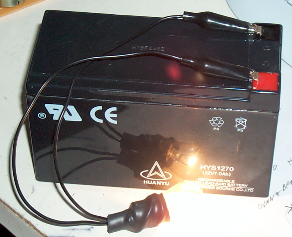 So now I have made up a simple 12 Volt
battery checker that's just a number 1156 car tail light
bulb soldered to a clip lead that was cut in half.
This pulls a couple of amps to light brightly and with only
1 amp will take some seconds to light dimly. This
works much better than the Radio Shack 22-080 battery tester
that shows a dead battery as good.
So now I have made up a simple 12 Volt
battery checker that's just a number 1156 car tail light
bulb soldered to a clip lead that was cut in half.
This pulls a couple of amps to light brightly and with only
1 amp will take some seconds to light dimly. This
works much better than the Radio Shack 22-080 battery tester
that shows a dead battery as good.Note that the very common 12 V 7 AH batteries come with both 1/4" (0.250") and 3/16" (0.187) quick connect type terminals. On the batteries I got some are 1/4" and some are 3/16". So you need to check each battery, even though at a quick glance they look the same.
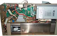
Construction
Top Side
Under the top cover the brick power supply is on the right. Beside it is a tray that could hold rechargeable batteries. There's a 4 position Molex connector with 3 sockets installed on wires that are Red, Black and Orange marked "26" that's probably the battery pack connector. There is a PCB behind the left metered panel and another PCB behind the setup controls located behind the door on the right.Chicago Miniature CMD series LED's.
Red CMD57124A
Yellow CMD 53124A
Green CMD54124A
Patents
The upper left box is marked Model 5030M/201/S25, s/n 199, U.S. Patent 4499433.4499433 Autolock for resonators for frequency standards Feb 12, 1985 Class 331/3; 331/94.1
A system is disclosed for examining the response in atomic and molecular resonators to identify and select the maximum resonant peak and the voltage used to cause said peak to be produced. The system is fabricated of modular elements electrically connected to a circuit board to facilitate its construction and transportation with the resonator. A microprocessor is utilized to perform the analysis and to generate information to select the maximum resonant peak, and the system includes means to compare the value of successively generated resonator outputs and to select the output with the maximum peak.3967115 Atomic beam tube June 29, 1976 250/251; 331/3; 331/94.1 by FTS (3967115.pdf)
Class 331 is Oscillators and /3 is Molecular resonance stabilization
The idea of this invention is to use a microcontroller (RCA or Hughes 1802 CMOS) to sweep the control voltage to the 10 MHz OCXO across it's range and watch the CBT output peaks and valleys. By looking for a peak with aproximate equal valued adajacent valleys on both sides the maximum peak can be selected and that peak used to lock the servo system tying to CBT to the 10 MHz reference. The three DAC1006 Digital to Analog converter chips that are part of the A/D system reading the CBT output voltage is potted in a clear compound probably to reduce elakage currents. J2 is the OCXO control voltage output.
Other FTS Patents
5721514 Digital frequency generation in atomic frequency standards using digital phase shifting February 24, 1998 331/3; 331/94.15714910 Methods and apparatus for digital frequency generation in atomic frequency standards February 3, 1998 331/3; 331/94.1
5656189 Heater controller for atomic frequency standards August 12, 1997 219/499; 219/210; 219/501; 219/505; 330/289; 331/1R; 331/69
5627497 Resonator package for atomic frequency standard May 6, 1997 331/94.1; 331/3
4862101 System for producing spectrally pure optical pumping light August 29, 1989 359/345; 359/886
4588969 Adjustable crystal oscillator with acceleration compensation May 13, 1986 331/156; 331/175; 331/177V
4586006 Crystal oscillator assembly April 29, 1986 331/69; 219/210; 331/70; 331/158
Other Patents
4899117 High accuracy frequency standard and clock system, Vig; John R, Feb 6, 1990, 331/3 ; 331/176; 331/44; 331/47; 368/202; 368/56"Moreover, in rubidium
frequency standards, the available C-field adjustment range
limits the useful life of the unit. For example, in one of
the most popular rubidium frequency standards currently on
the market, the manufacturer provides a C-field adjustment
range equivalent to +1.5.times.10.sup.-9. The aging rate of
the standard is specified as 2.times.10.sup.-10 per year.
Consequently, at the specified aging rate, the limited
C-field adjustment range limits the useful life of this
rubidium frequency standard to 1.5.times.10.sup.-9
/2.times.10.sup.-10 =7.5 years."
5146184 Atomic clock system with improved
servo system, Cutler; Len, Sep 8, 1992, 331/3 ;
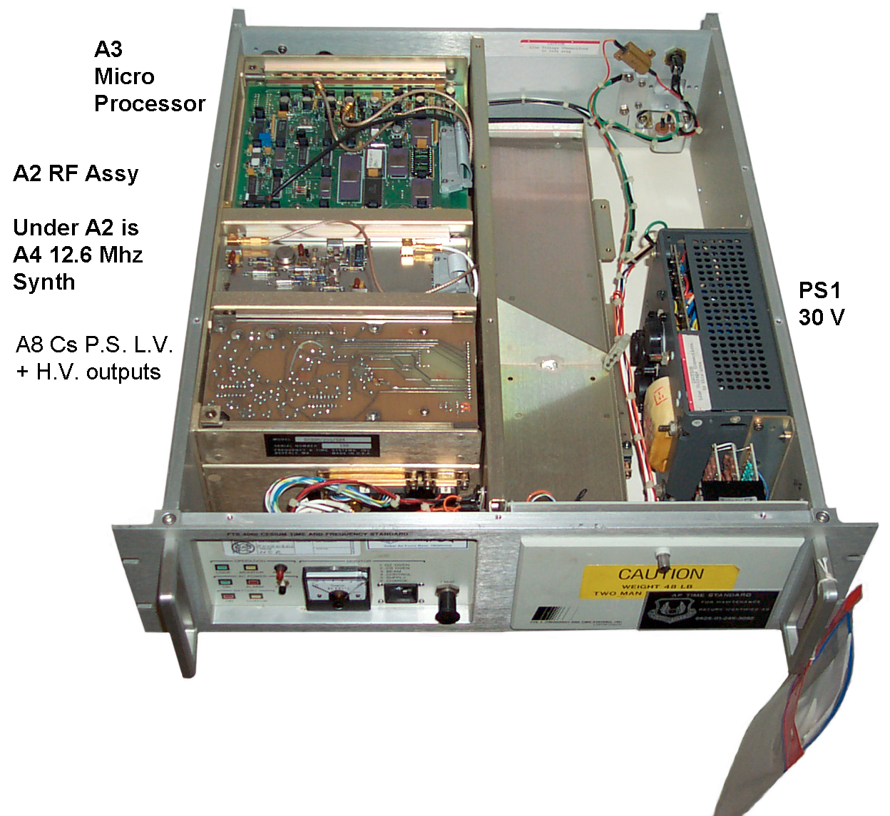
331/79 Inside the 4060/S24
J3 is the signal coming from the
I/F PCB of the CBT. J4 is the 450 Hz output to the A7
X18 multiplier.
 At the left rear is the
microcontroller PCB.
At the left rear is the
microcontroller PCB.
There is a 40 conductor ribbon cable connection, 2 coax cables and a cable with 2 wires (Red and Black) going to A7 and TP2.
2:50 power on TP2 = 4.97 VDC and the front panel meter on 4 (control voltage) indicates about 5 volts. (2:50 pm)
2:56 Operation Monitor light turned off.
3:00 switching LOOP to Open and back to closed starts meter into sawtooth from 0 to 5 Volts. It takes about 21 seconds to sweep the monitor voltage from 0 to 5 Volts.
But TP2 is sitting at 4.98 VDC so must be a 5 Volt test point or it's some logic indicator that may be pointing to a problem.
21 July 2005 - A3-TP2 a test point to monitor the 450 Hz signal that goes to A7.
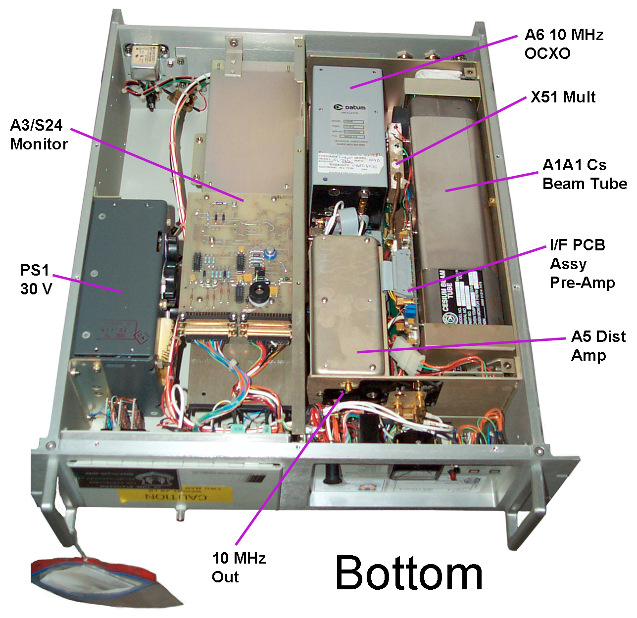
To the left of the CBT at the rear is the 10 MHz oscillaotr, marked: Model 1000B. In front of the 10 MHz osc. is The A5 Distrubution Amp metal box with an SMA-f connector just behind the front panel marked J3, RF1 which may be a 10 MHz signal that could be connected to the front or rear panels.
 Just
to
the
left
of
the
center
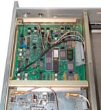
divider is the A3 Alarm PCB with 2 each DB-25 connectors and
no RF coax connections. Marked: D.1652 s/n 865009
(probably 1986 +...) It is not fully populated, missing a few
ICs and a number of discrete parts that probably are part of
the battery charging or monitoring circuit. The 30 VDC
brick power supply is up aginst the left wall.
Just
to
the
left
of
the
center
divider is the A3 Alarm PCB with 2 each DB-25 connectors and
no RF coax connections. Marked: D.1652 s/n 865009
(probably 1986 +...) It is not fully populated, missing a few
ICs and a number of discrete parts that probably are part of
the battery charging or monitoring circuit. The 30 VDC
brick power supply is up aginst the left wall.
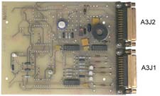
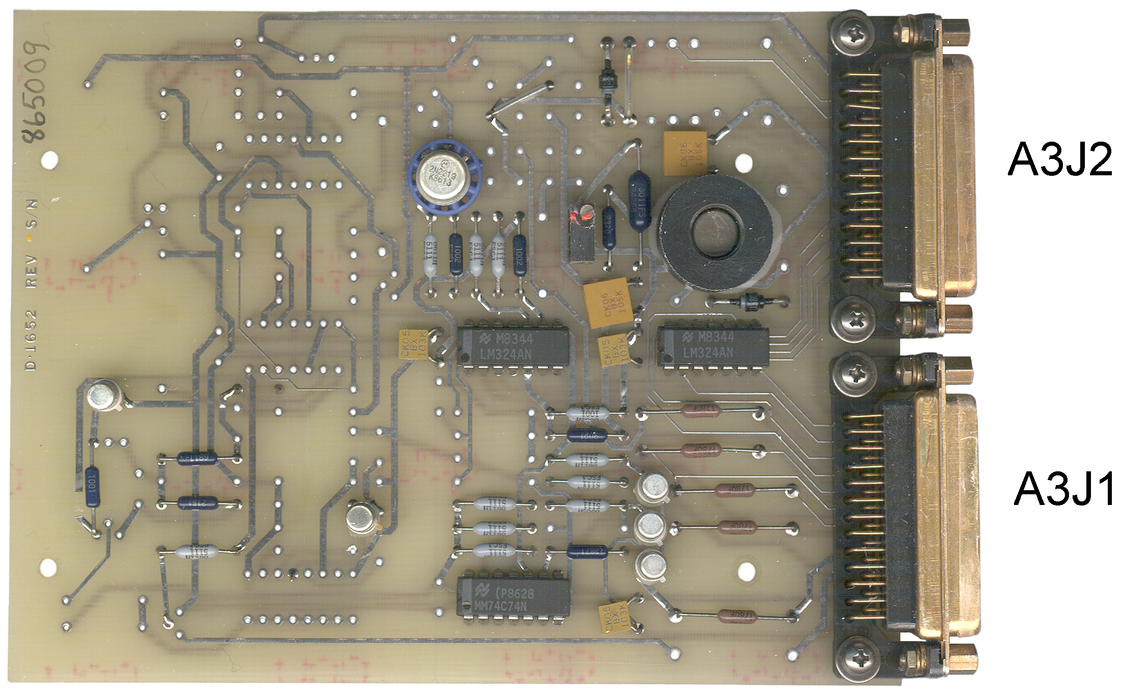
I have named the DB-25m connector nearer the powr supply A3J1 and the DB-25m near the center divider A3J2 since there's no markings on either.
A3J1 pins 23, 22, 24, 25, 2 and 6 are connected to the Monitor thumb wheel switch positions 1 thorough 6 respectively and the switch common goes through the front panel meter to ground.
The Battery Charge, AC Power Alrarm, Battery On andAC Power On LEDs are connected to A3J1 pins 4, 5, 6 and 9 respectively.
Five of the wires on A3J2 are connected to the 5030 Assembly J1 connector.
A3J1 pins 1, 13 and 18 and connected to A3J2 pins 1,2,5,6,8,13 which is probably ground.
 At the left rear is the
microcontroller PCB.
At the left rear is the
microcontroller PCB.There is a 40 conductor ribbon cable connection, 2 coax cables and a cable with 2 wires (Red and Black) going to A7 and TP2.
2:50 power on TP2 = 4.97 VDC and the front panel meter on 4 (control voltage) indicates about 5 volts. (2:50 pm)
2:56 Operation Monitor light turned off.
3:00 switching LOOP to Open and back to closed starts meter into sawtooth from 0 to 5 Volts. It takes about 21 seconds to sweep the monitor voltage from 0 to 5 Volts.
But TP2 is sitting at 4.98 VDC so must be a 5 Volt test point or it's some logic indicator that may be pointing to a problem.
21 July 2005 - A3-TP2 a test point to monitor the 450 Hz signal that goes to A7.
Bottom Side
The Cesium Beam Tube is on the right, marked: Cesium Beam Tube, Model FTS-7103, p/n 08923-501, NSN 5960-01-214-7475.To the left of the CBT at the rear is the 10 MHz oscillaotr, marked: Model 1000B. In front of the 10 MHz osc. is The A5 Distrubution Amp metal box with an SMA-f connector just behind the front panel marked J3, RF1 which may be a 10 MHz signal that could be connected to the front or rear panels.
A3 Alarm
 Just
to
the
left
of
the
center
divider is the A3 Alarm PCB with 2 each DB-25 connectors and
no RF coax connections. Marked: D.1652 s/n 865009
(probably 1986 +...) It is not fully populated, missing a few
ICs and a number of discrete parts that probably are part of
the battery charging or monitoring circuit. The 30 VDC
brick power supply is up aginst the left wall.
Just
to
the
left
of
the
center
divider is the A3 Alarm PCB with 2 each DB-25 connectors and
no RF coax connections. Marked: D.1652 s/n 865009
(probably 1986 +...) It is not fully populated, missing a few
ICs and a number of discrete parts that probably are part of
the battery charging or monitoring circuit. The 30 VDC
brick power supply is up aginst the left wall.I have named the DB-25m connector nearer the powr supply A3J1 and the DB-25m near the center divider A3J2 since there's no markings on either.
A3J1 pins 23, 22, 24, 25, 2 and 6 are connected to the Monitor thumb wheel switch positions 1 thorough 6 respectively and the switch common goes through the front panel meter to ground.
The Battery Charge, AC Power Alrarm, Battery On andAC Power On LEDs are connected to A3J1 pins 4, 5, 6 and 9 respectively.
Five of the wires on A3J2 are connected to the 5030 Assembly J1 connector.
A3J1 pins 1, 13 and 18 and connected to A3J2 pins 1,2,5,6,8,13 which is probably ground.
5030 Assembly
The Physics package might be
defined as the combination of the Cesium beam tube, the Times
51 Multiplier and the Interface PCB since the latter two items
are bolted to the side of the Cesium Beam Tube.
The Physics Package is in turn a part of the 5030 Assembly. In addition to the Physics Package the 5030 assembly has Most of the parts except the PS1 30 Volt power supply and the A3 Alarm 5 x 6" PCB, and the front and rear panels. The 5030 Assembly is 16 x 7.75 x 5 inches.
 To
remove
the
5030
Assembly
remove
the
four 5/32" hex cap bolts, being careful to not let the 5030
assembly crash and move it so that you can easily get to the
SMA connectors and the #2 Philips screws on the "D"
connectors.
To
remove
the
5030
Assembly
remove
the
four 5/32" hex cap bolts, being careful to not let the 5030
assembly crash and move it so that you can easily get to the
SMA connectors and the #2 Philips screws on the "D"
connectors.
Check to see that the 3 Coax cables are marked 4 (Zeeman audio in), 5 (Rear 1 MHz out) and 7(Front 1 MHz out) that mate to J4, J5 and J7, then disconnect these SMA cables.
Remove the two "D" connectors using a #2 Philips screwdriver and lift the 5030 Assembly free of the chassis.
The Physics Package is in turn a part of the 5030 Assembly. In addition to the Physics Package the 5030 assembly has Most of the parts except the PS1 30 Volt power supply and the A3 Alarm 5 x 6" PCB, and the front and rear panels. The 5030 Assembly is 16 x 7.75 x 5 inches.
 To
remove
the
5030
Assembly
remove
the
four 5/32" hex cap bolts, being careful to not let the 5030
assembly crash and move it so that you can easily get to the
SMA connectors and the #2 Philips screws on the "D"
connectors.
To
remove
the
5030
Assembly
remove
the
four 5/32" hex cap bolts, being careful to not let the 5030
assembly crash and move it so that you can easily get to the
SMA connectors and the #2 Philips screws on the "D"
connectors.Check to see that the 3 Coax cables are marked 4 (Zeeman audio in), 5 (Rear 1 MHz out) and 7(Front 1 MHz out) that mate to J4, J5 and J7, then disconnect these SMA cables.
Remove the two "D" connectors using a #2 Philips screwdriver and lift the 5030 Assembly free of the chassis.
Note It is an easy job to
replace the 5030 Assembly and that may allow using the
complete 5030 Assembly from a working /S24 unit to bring a
defunct FTS4060 back on line. This can be done in a
few minutes. But I don't know where the additional
modules are located on a full featured 4060. If they
are on the right side ( the 5030 is on the left side) then
it would be very easy. If they are in the way of
removing the 5030 Assembly then it would take longer.
On the upper left is the 10 MHz OCXO.
At the upper right is the A5 Distribution Amplifier.
This amy be an A5/S24 with the front 10 Mhz output
missing.
 By first labeling all the coax
cable ends that will be disconnected, then by removing 2
(+) screws and loosening 2 (-) captive screws and
disconnecting some connectors (no soldering needed) the
combined A5 & A7 assembly can easily be removed.
By first labeling all the coax
cable ends that will be disconnected, then by removing 2
(+) screws and loosening 2 (-) captive screws and
disconnecting some connectors (no soldering needed) the
combined A5 & A7 assembly can easily be removed.
A1A5 Distribution Amp
My units have an A5 amplifier that has a open SMA-f
connector facing forward and that connector has a 10 MHz
signal that's about 4.4 Volts Pk-Pk. But other /S24
units have the connector and some internal parts removed
and so don't have the 10 MHz easy to connect.
The cable from the A5 10 Mhz output to the rear panel is about 40" long, SMA(m) on the A5 end and a bulkhead BNC(f) for the rear panel
 The
5030
assembly
mother
board
can
be
seen once the A5+A7 sub assembly is removed. All the
components in the 5030 assembly interface to the mother
board. This greatly minimizes the wiring
clutter. There may be a dozen components on the
mother board.
The
5030
assembly
mother
board
can
be
seen once the A5+A7 sub assembly is removed. All the
components in the 5030 assembly interface to the mother
board. This greatly minimizes the wiring
clutter. There may be a dozen components on the
mother board.
Max dimensions are about 12" x 5" although it's "L" shaped.
 Here
only the A1A2 motherboard and the A1A9 input filter at
attached to the 5030 frame.
Here
only the A1A2 motherboard and the A1A9 input filter at
attached to the 5030 frame.
The right hand narrow part is just to get the 40 conductor ribbon cable lined up with the A1A3 uP board.
 Dataum 1000B Ultra-Stable 10
MHz oscillator (now Symmetricom
1000B). This is a brick about 3x3x7inches with
all the connections on one of the 3x3" ends. Part
number is 05818-119. There's a DB-9 connector with
the following pinout:
Dataum 1000B Ultra-Stable 10
MHz oscillator (now Symmetricom
1000B). This is a brick about 3x3x7inches with
all the connections on one of the 3x3" ends. Part
number is 05818-119. There's a DB-9 connector with
the following pinout:
The oven insulation is my means of a dewar. The initial aging rate might be <1E-10 per day when new, but can get below 1E-12 after running for some time. The phase noise is lower than -134 dB at 10 Hz, -144 dB at 100 Hz and -157 dB at 1 kHz.
The 10 Mhz output is from a right angle SMB connector pointing down. (All the small coax is terminated with 50 Ohm SMB connectors in the FTS4060).
On top of the 1000B (p/n 05818-119) there's a coarse frequency adjust pot.
To remove the USO three 1/4" nuts need to be removed that are below the A3 uP board and the connectors disconnected.
Some data on a hand picked 100B:
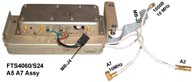
A1A7 x18 Mult & Mixer
 Just under the A5 Amplifier is the
Times 18 Frequency Multiplier (10 MHz in, 180 MHz out) and
mixer.
Just under the A5 Amplifier is the
Times 18 Frequency Multiplier (10 MHz in, 180 MHz out) and
mixer.
As seen in the photo the connectors are: 10 MHz in, connector with Black, Gnd, and Red wires going to J4 on the A3 Microprocessor board. Cable with Black, Red, Green (ground) & blue wires soldered to feedthroughs going to connector J4 on Cesium Beam Tube motherboard.. 12.6 MHz input & 180 MHz output.
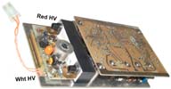 In the
lower right corner is the A8 Power Supply for the Cesium
Beam Tube that includes the two HIGH VOLTAGE outputs.
The bottom of this PCB is visible at the top left front when
the top cover is removed. You might not
want to have your hands anywhere near this board when power
is applied.
In the
lower right corner is the A8 Power Supply for the Cesium
Beam Tube that includes the two HIGH VOLTAGE outputs.
The bottom of this PCB is visible at the top left front when
the top cover is removed. You might not
want to have your hands anywhere near this board when power
is applied.
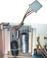 Although
this
PCB
is
in
a
slot
and should be able to slide out, it's trapped by the female
thread fitting used to attach the 5030 sub assembly to the
chassis. It has a dual electrolytic cap, a single
electrolytic cap, a diode and an inductor.
Although
this
PCB
is
in
a
slot
and should be able to slide out, it's trapped by the female
thread fitting used to attach the 5030 sub assembly to the
chassis. It has a dual electrolytic cap, a single
electrolytic cap, a diode and an inductor.
 At the
bottom center is the 3 x 7" A2/S24 RF Assembly
(56219-05280-011 Assy 05281) that takes in 10 MHz and
outputs 1 MHz. On a full featured 4060 this board
would also output 100 kHz and 10 MHz.
At the
bottom center is the 3 x 7" A2/S24 RF Assembly
(56219-05280-011 Assy 05281) that takes in 10 MHz and
outputs 1 MHz. On a full featured 4060 this board
would also output 100 kHz and 10 MHz.
It may that the 74LS90 divide by 10 circuit could be bypassed to allow two 10 MHz outputs instead of the two 1 MHz outputs that are on the /S24 versions.
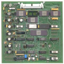 The A3
board has a coax input (J2) that takes in the error signal
from the Cs interface board. It also has a coax EFT
output (J3) to drive the Ultra-stable 10 MHz oscillator
(A6). The 450 Hz signal is generated on this board
and feeds A7. 40 pin connector J1 has a number of
analog signal inputs and outputs as will as digital inputs
and outputs.
The A3
board has a coax input (J2) that takes in the error signal
from the Cs interface board. It also has a coax EFT
output (J3) to drive the Ultra-stable 10 MHz oscillator
(A6). The 450 Hz signal is generated on this board
and feeds A7. 40 pin connector J1 has a number of
analog signal inputs and outputs as will as digital inputs
and outputs.
With J1 pointing up in the photo at left the two TO-5 cans in the upper left are the +15 and -15 volt supplies for the analog Op amps, sample/hold and DAC circuits comprsing the left analog part fo the board.
The uP is an 1802.
DAC1006 D/A converters are used both for A/D conversion with a comparator and for D/A output to the meter and Ultra-Stable Oscillator.
 Directly
under
the
A2
board
is
another
same size board, the A1A4 12.6 MHz Synthesizer (56219 Assy)
that shares the same 14 conductor ribbon cable and has a
single coax cable that goes to the times 18
Multiplier. There are a half dozen Synchronous
Four-Bit Counter 54LS161
ICs on this board.
Directly
under
the
A2
board
is
another
same size board, the A1A4 12.6 MHz Synthesizer (56219 Assy)
that shares the same 14 conductor ribbon cable and has a
single coax cable that goes to the times 18
Multiplier. There are a half dozen Synchronous
Four-Bit Counter 54LS161
ICs on this board.
A1A1 Cesium Beam Tube Assembly (Physics Package)
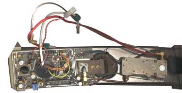 The
tube is really straight, but the photo gives it a curved
appearance because of perspective.
The
tube is really straight, but the photo gives it a curved
appearance because of perspective.
The A1 Cesium beam tube is held at each end by an angle bracket that has 3 large philips screws holding it to the 5030 frame. One of these is under the A8 power supply and the other is under the A3 uP board.
The x51 Multiplier and the Cesium Beam Tube Interface PCB are attached to the tube.
Connections to the rest of the system are by means of:
Red & white High voltage wires, twisted pair of orange wires to Cs PS
coax with 180 MHz from A7 to X51 mult.
26 conductor ribbon cable to mother board W5
Coax with error signal from interface board to A3 uP board.
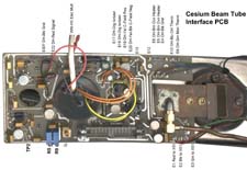 This
board
is
where
most
of
the
wires coming out of the CBT are soldered. The E26
Test Point is missing. The wires coming from
theDetector Heater are labeled along with the "E" number
of the board terminals.
This
board
is
where
most
of
the
wires coming out of the CBT are soldered. The E26
Test Point is missing. The wires coming from
theDetector Heater are labeled along with the "E" number
of the board terminals.
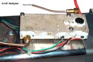
The x51 Microwave multiplier gets it's RF input from the
A1A7 X18 Multiplier - Mixer and feeds it's output to the
waveguide adapter on the CBT. The Red, Green and
Black wires come from the CBT interface PCB.
On the upper left is the 10 MHz OCXO.
A1A5 Dist AMP
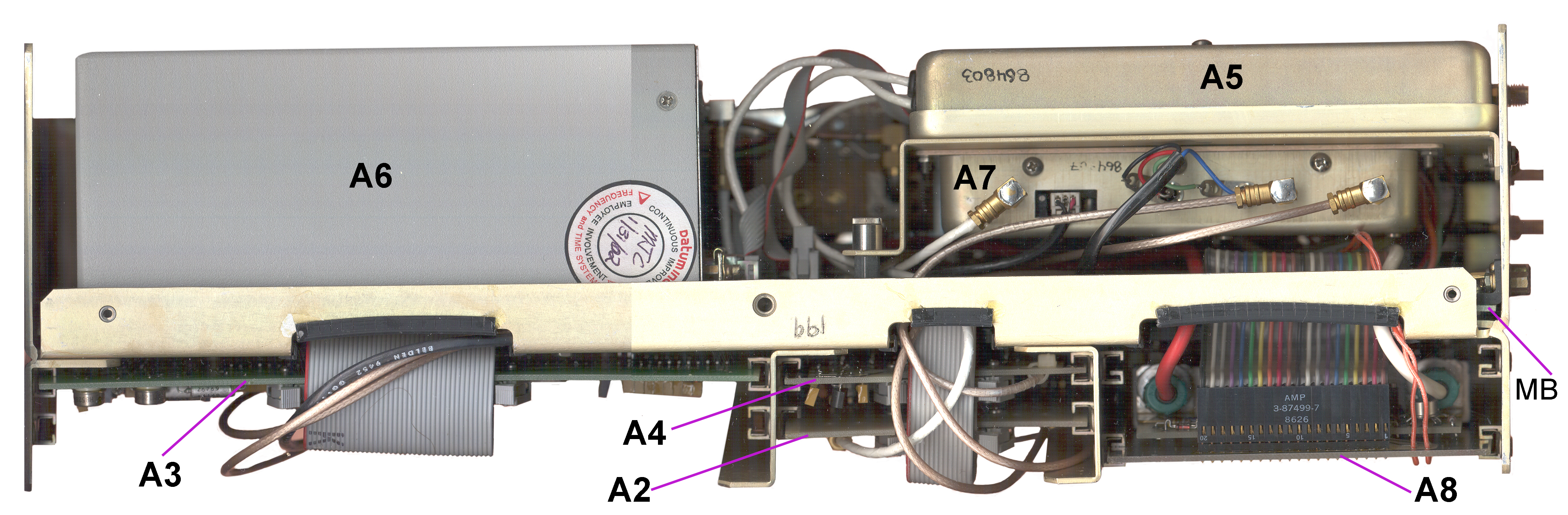
A1A5 & A1A7 Sub Assembly
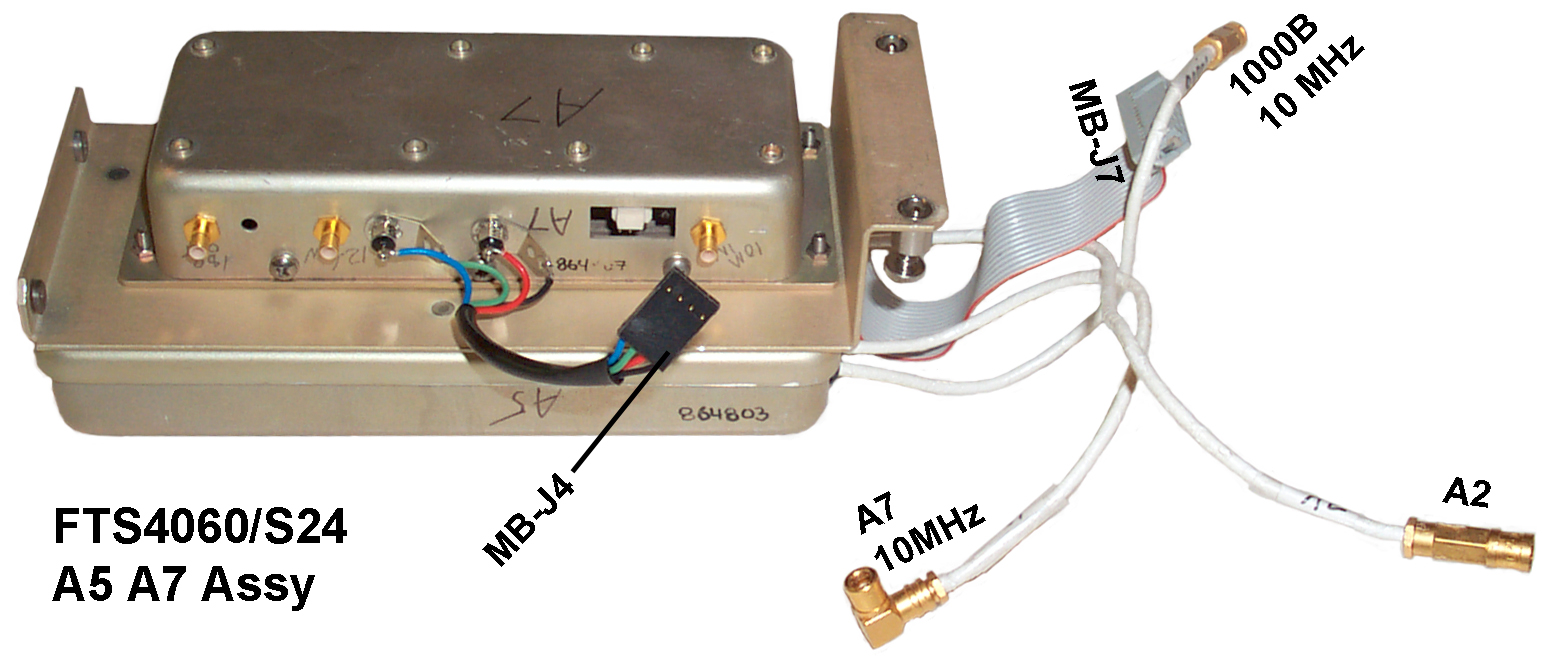 By first labeling all the coax
cable ends that will be disconnected, then by removing 2
(+) screws and loosening 2 (-) captive screws and
disconnecting some connectors (no soldering needed) the
combined A5 & A7 assembly can easily be removed.
By first labeling all the coax
cable ends that will be disconnected, then by removing 2
(+) screws and loosening 2 (-) captive screws and
disconnecting some connectors (no soldering needed) the
combined A5 & A7 assembly can easily be removed.
A1A5 Distribution Amp
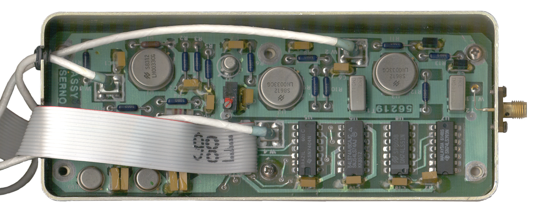
The cable from the A5 10 Mhz output to the rear panel is about 40" long, SMA(m) on the A5 end and a bulkhead BNC(f) for the rear panel
A1A2 Mother Board
 The
5030
assembly
mother
board
can
be
seen once the A5+A7 sub assembly is removed. All the
components in the 5030 assembly interface to the mother
board. This greatly minimizes the wiring
clutter. There may be a dozen components on the
mother board.
The
5030
assembly
mother
board
can
be
seen once the A5+A7 sub assembly is removed. All the
components in the 5030 assembly interface to the mother
board. This greatly minimizes the wiring
clutter. There may be a dozen components on the
mother board.Max dimensions are about 12" x 5" although it's "L" shaped.
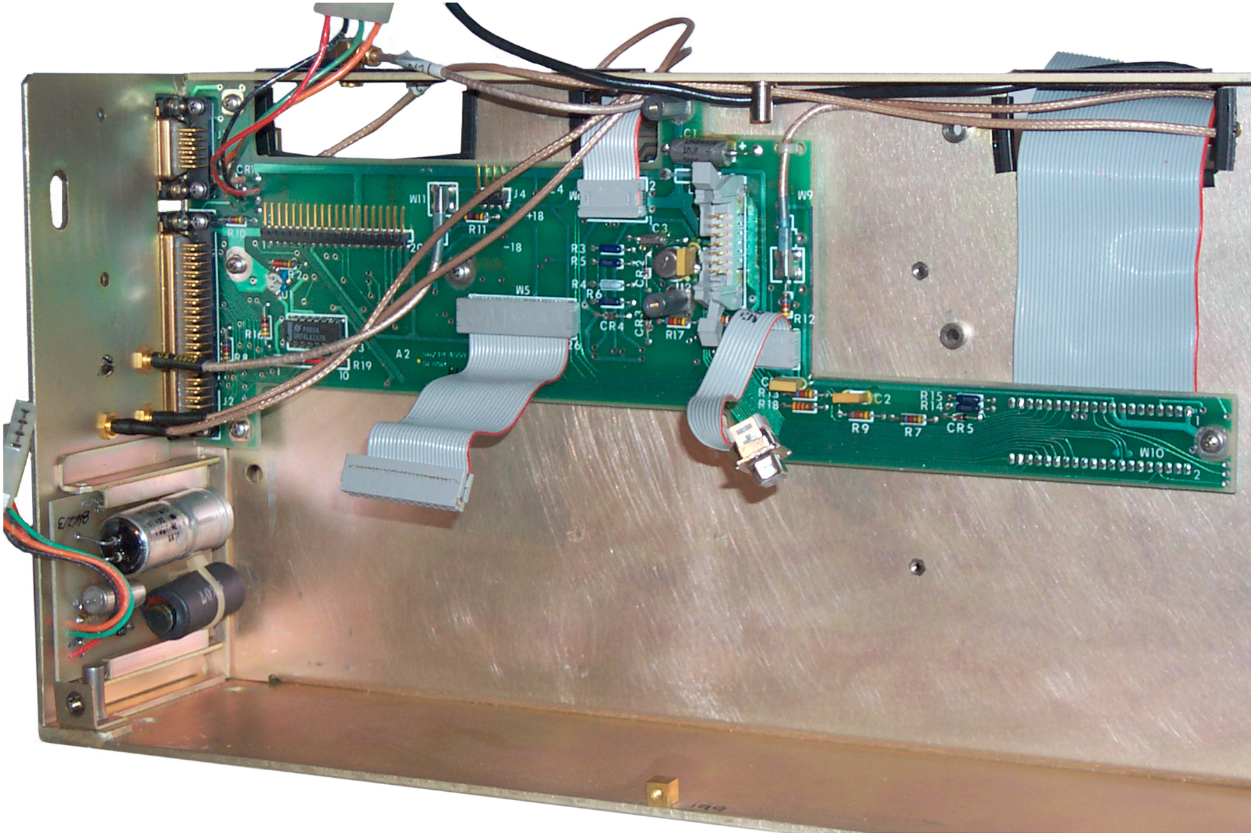 Here
only the A1A2 motherboard and the A1A9 input filter at
attached to the 5030 frame.
Here
only the A1A2 motherboard and the A1A9 input filter at
attached to the 5030 frame.The right hand narrow part is just to get the 40 conductor ribbon cable lined up with the A1A3 uP board.
A1A6 Ultra-stable Oscillator
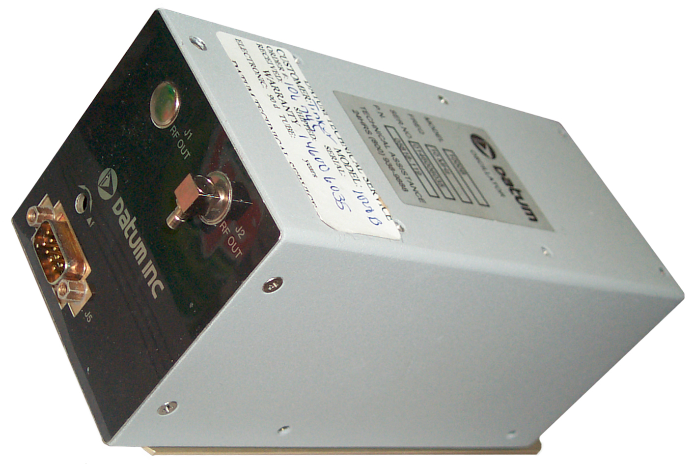 Dataum 1000B Ultra-Stable 10
MHz oscillator (now Symmetricom
1000B). This is a brick about 3x3x7inches with
all the connections on one of the 3x3" ends. Part
number is 05818-119. There's a DB-9 connector with
the following pinout:
Dataum 1000B Ultra-Stable 10
MHz oscillator (now Symmetricom
1000B). This is a brick about 3x3x7inches with
all the connections on one of the 3x3" ends. Part
number is 05818-119. There's a DB-9 connector with
the following pinout:| Pin |
Function |
| 1 |
Electronic
gnd |
| 2 |
Freq
Ctrl Voltage in (-10 to +10) |
| 3 |
Coarse
tune in voltage |
| 4 |
+12
V ref (coarse tune hot) |
| 5 |
Oven
gnd |
| 6 |
Oven
Control monitor |
| 7 |
+24
VDC Oven power |
| 8 |
Electronic
+24
VDC pwr |
| 9 |
Case
Gnd |
The oven insulation is my means of a dewar. The initial aging rate might be <1E-10 per day when new, but can get below 1E-12 after running for some time. The phase noise is lower than -134 dB at 10 Hz, -144 dB at 100 Hz and -157 dB at 1 kHz.
The 10 Mhz output is from a right angle SMB connector pointing down. (All the small coax is terminated with 50 Ohm SMB connectors in the FTS4060).
On top of the 1000B (p/n 05818-119) there's a coarse frequency adjust pot.
To remove the USO three 1/4" nuts need to be removed that are below the A3 uP board and the connectors disconnected.
Some data on a hand picked 100B:
A1A7 x18 Mult & Mixer
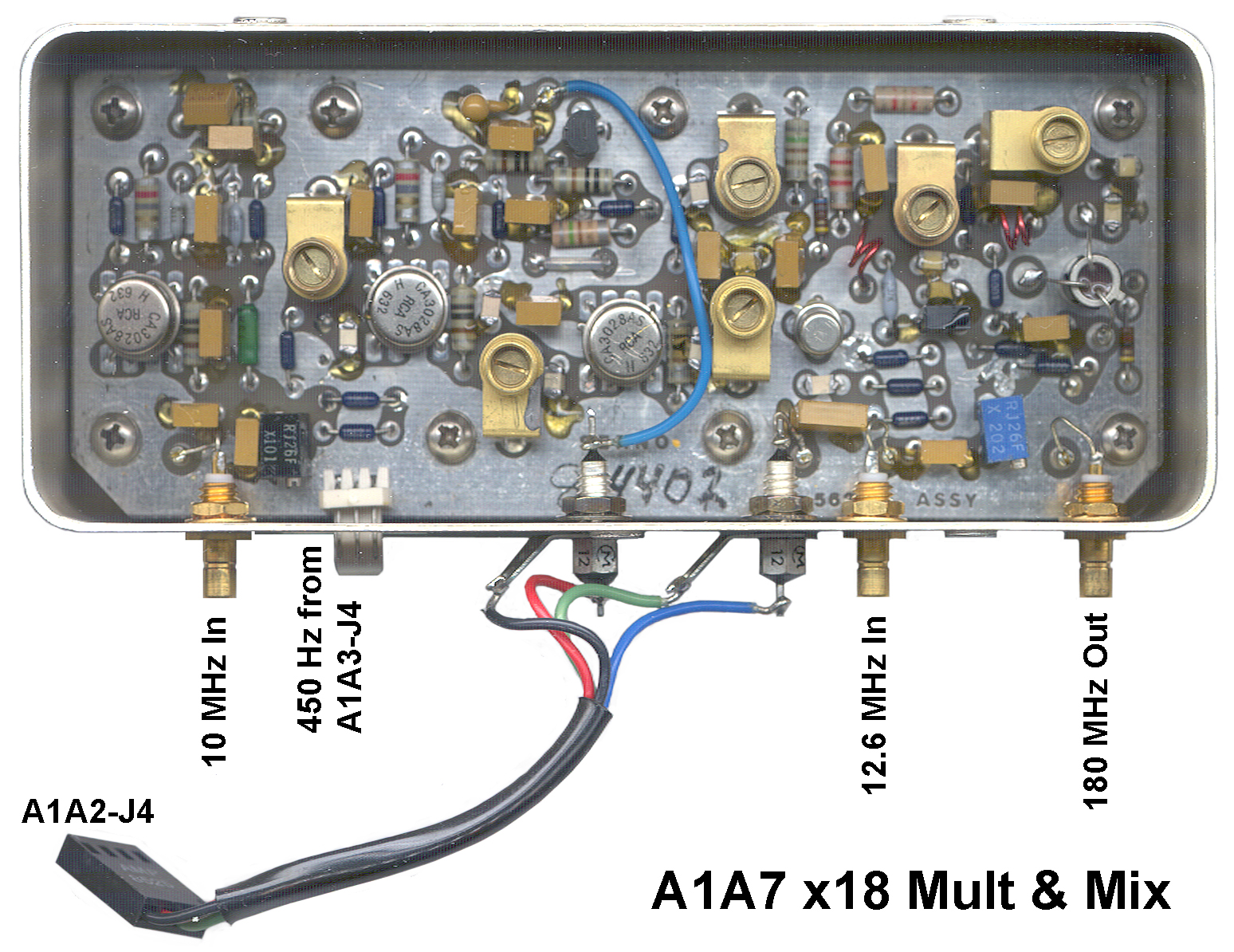 Just under the A5 Amplifier is the
Times 18 Frequency Multiplier (10 MHz in, 180 MHz out) and
mixer.
Just under the A5 Amplifier is the
Times 18 Frequency Multiplier (10 MHz in, 180 MHz out) and
mixer. As seen in the photo the connectors are: 10 MHz in, connector with Black, Gnd, and Red wires going to J4 on the A3 Microprocessor board. Cable with Black, Red, Green (ground) & blue wires soldered to feedthroughs going to connector J4 on Cesium Beam Tube motherboard.. 12.6 MHz input & 180 MHz output.
A1A8 Cs Power Supply
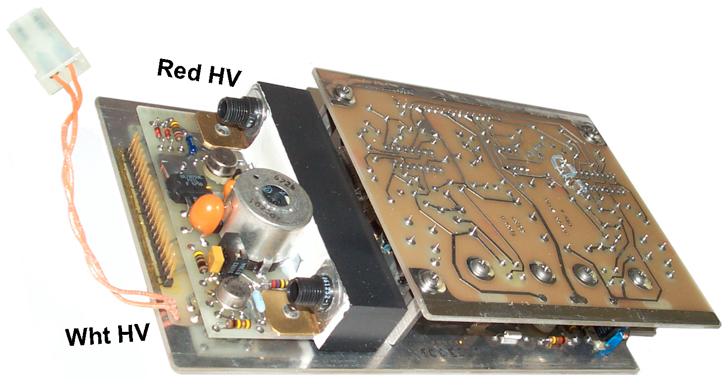 In the
lower right corner is the A8 Power Supply for the Cesium
Beam Tube that includes the two HIGH VOLTAGE outputs.
The bottom of this PCB is visible at the top left front when
the top cover is removed. You might not
want to have your hands anywhere near this board when power
is applied.
In the
lower right corner is the A8 Power Supply for the Cesium
Beam Tube that includes the two HIGH VOLTAGE outputs.
The bottom of this PCB is visible at the top left front when
the top cover is removed. You might not
want to have your hands anywhere near this board when power
is applied.A1A9 DC Input Filter
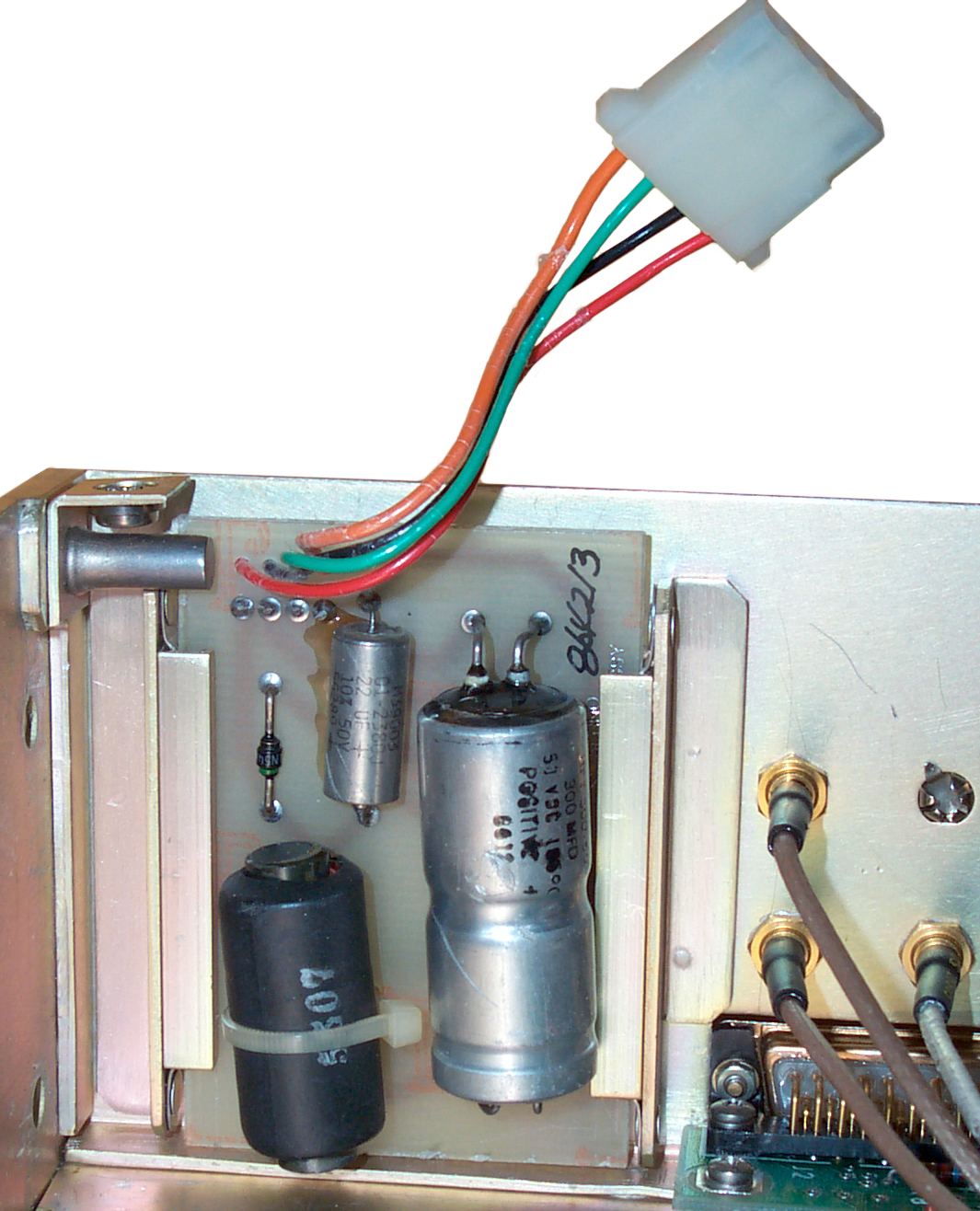 Although
this
PCB
is
in
a
slot
and should be able to slide out, it's trapped by the female
thread fitting used to attach the 5030 sub assembly to the
chassis. It has a dual electrolytic cap, a single
electrolytic cap, a diode and an inductor.
Although
this
PCB
is
in
a
slot
and should be able to slide out, it's trapped by the female
thread fitting used to attach the 5030 sub assembly to the
chassis. It has a dual electrolytic cap, a single
electrolytic cap, a diode and an inductor.A2 RF Assebmly
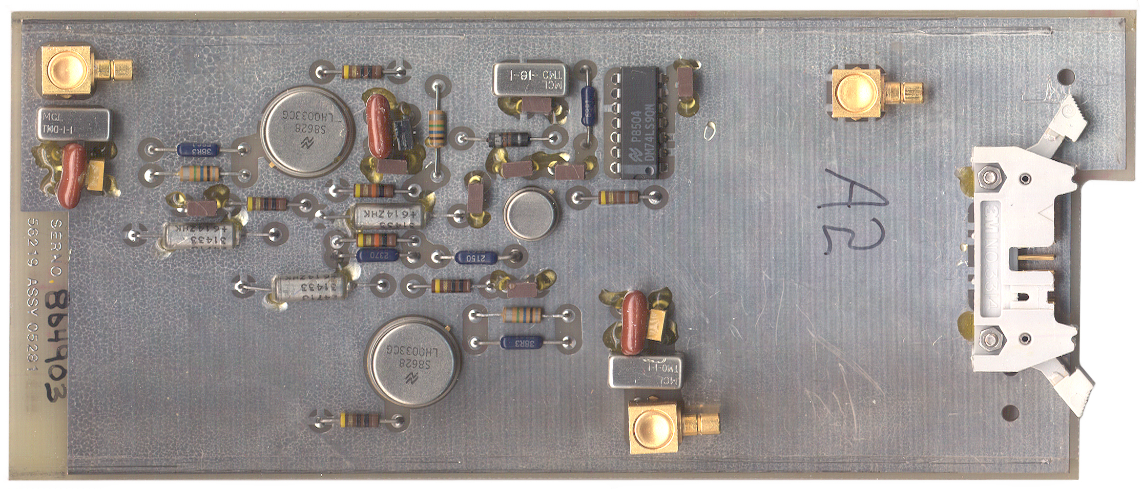 At the
bottom center is the 3 x 7" A2/S24 RF Assembly
(56219-05280-011 Assy 05281) that takes in 10 MHz and
outputs 1 MHz. On a full featured 4060 this board
would also output 100 kHz and 10 MHz.
At the
bottom center is the 3 x 7" A2/S24 RF Assembly
(56219-05280-011 Assy 05281) that takes in 10 MHz and
outputs 1 MHz. On a full featured 4060 this board
would also output 100 kHz and 10 MHz. It may that the 74LS90 divide by 10 circuit could be bypassed to allow two 10 MHz outputs instead of the two 1 MHz outputs that are on the /S24 versions.
A1A3 Micro Processor Board
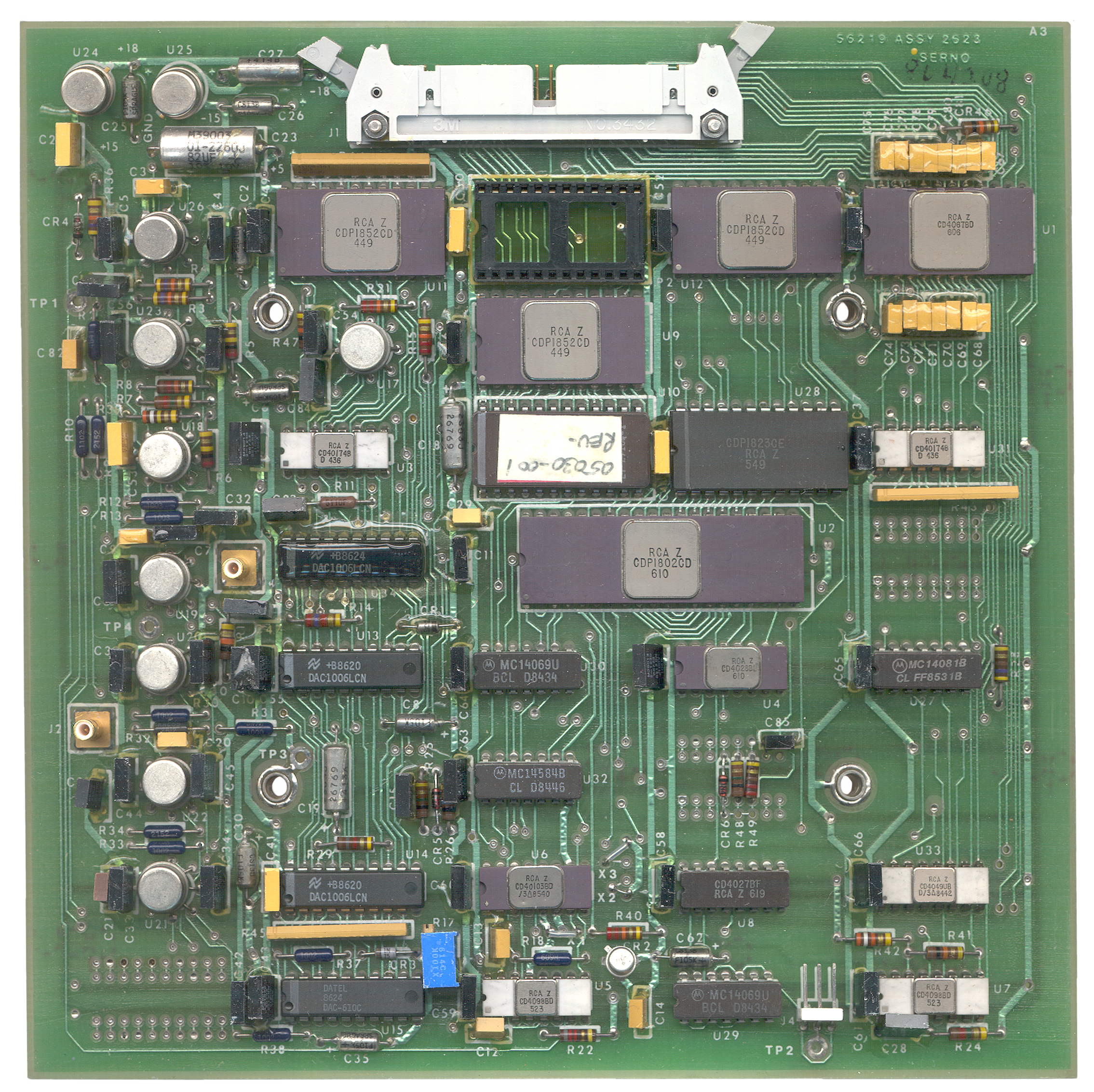 The A3
board has a coax input (J2) that takes in the error signal
from the Cs interface board. It also has a coax EFT
output (J3) to drive the Ultra-stable 10 MHz oscillator
(A6). The 450 Hz signal is generated on this board
and feeds A7. 40 pin connector J1 has a number of
analog signal inputs and outputs as will as digital inputs
and outputs.
The A3
board has a coax input (J2) that takes in the error signal
from the Cs interface board. It also has a coax EFT
output (J3) to drive the Ultra-stable 10 MHz oscillator
(A6). The 450 Hz signal is generated on this board
and feeds A7. 40 pin connector J1 has a number of
analog signal inputs and outputs as will as digital inputs
and outputs.With J1 pointing up in the photo at left the two TO-5 cans in the upper left are the +15 and -15 volt supplies for the analog Op amps, sample/hold and DAC circuits comprsing the left analog part fo the board.
The uP is an 1802.
DAC1006 D/A converters are used both for A/D conversion with a comparator and for D/A output to the meter and Ultra-Stable Oscillator.
A1A4 12.6 MHz Synthesizer
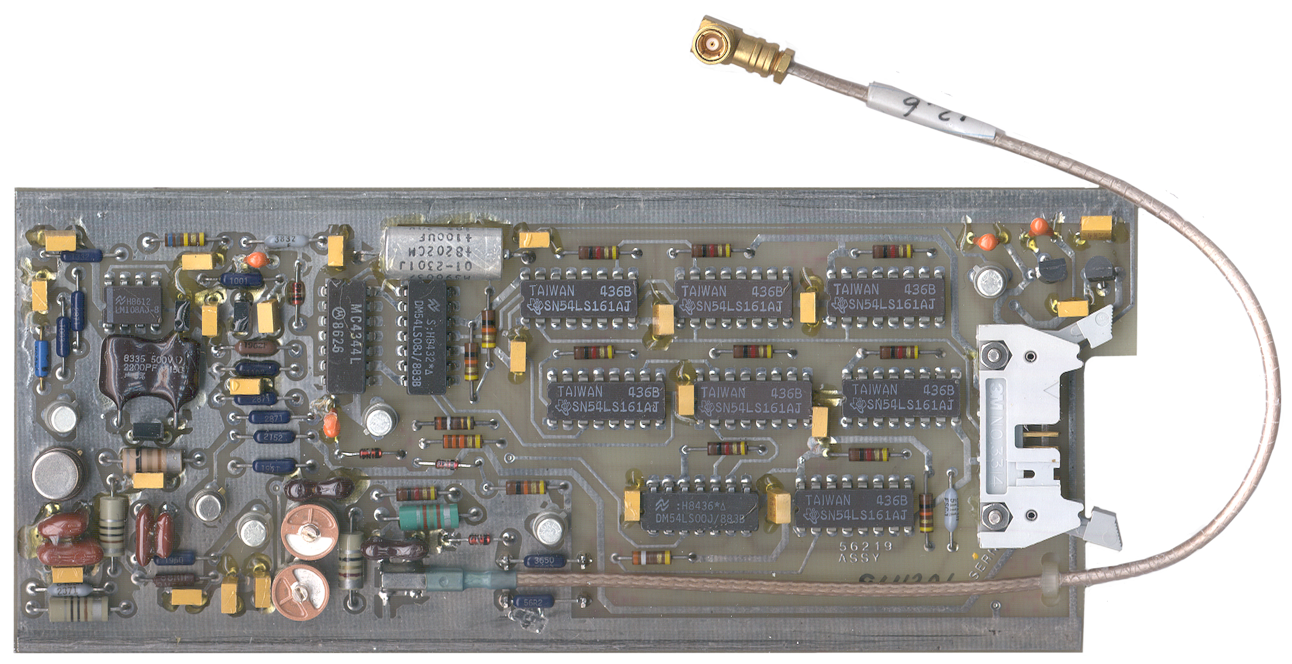 Directly
under
the
A2
board
is
another
same size board, the A1A4 12.6 MHz Synthesizer (56219 Assy)
that shares the same 14 conductor ribbon cable and has a
single coax cable that goes to the times 18
Multiplier. There are a half dozen Synchronous
Four-Bit Counter 54LS161
ICs on this board.
Directly
under
the
A2
board
is
another
same size board, the A1A4 12.6 MHz Synthesizer (56219 Assy)
that shares the same 14 conductor ribbon cable and has a
single coax cable that goes to the times 18
Multiplier. There are a half dozen Synchronous
Four-Bit Counter 54LS161
ICs on this board. A1A1 Cesium Beam Tube Assembly (Physics Package)
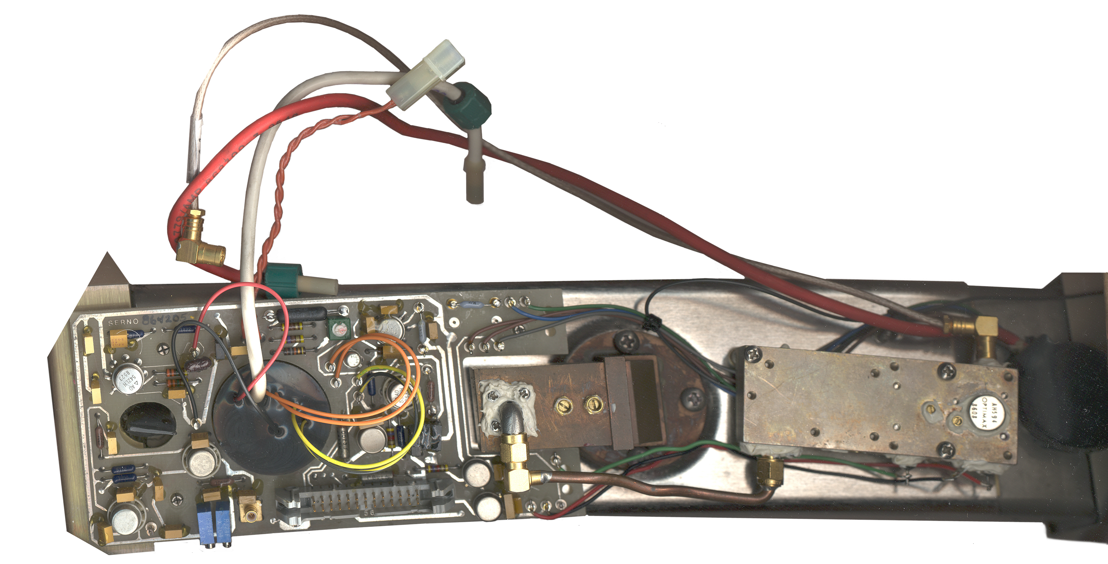 The
tube is really straight, but the photo gives it a curved
appearance because of perspective.
The
tube is really straight, but the photo gives it a curved
appearance because of perspective.The A1 Cesium beam tube is held at each end by an angle bracket that has 3 large philips screws holding it to the 5030 frame. One of these is under the A8 power supply and the other is under the A3 uP board.
The x51 Multiplier and the Cesium Beam Tube Interface PCB are attached to the tube.
Connections to the rest of the system are by means of:
Red & white High voltage wires, twisted pair of orange wires to Cs PS
coax with 180 MHz from A7 to X51 mult.
26 conductor ribbon cable to mother board W5
Coax with error signal from interface board to A3 uP board.
Interface PCB
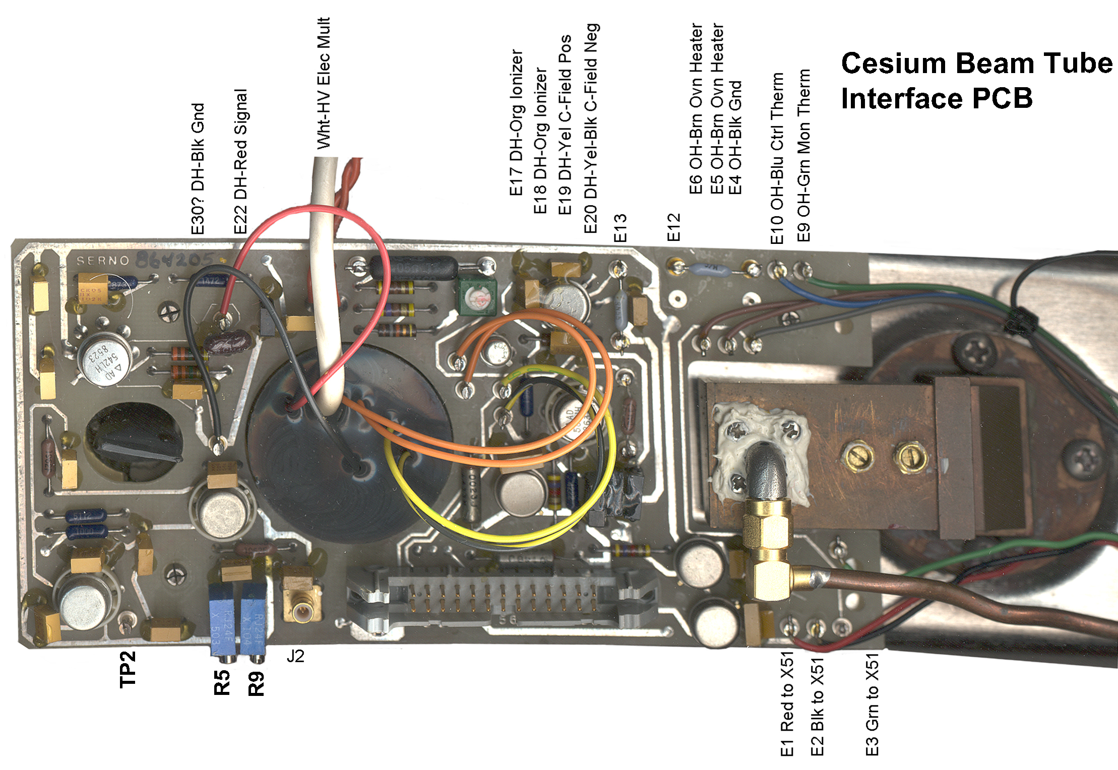 This
board
is
where
most
of
the
wires coming out of the CBT are soldered. The E26
Test Point is missing. The wires coming from
theDetector Heater are labeled along with the "E" number
of the board terminals.
This
board
is
where
most
of
the
wires coming out of the CBT are soldered. The E26
Test Point is missing. The wires coming from
theDetector Heater are labeled along with the "E" number
of the board terminals.X51 Microwave Multiplier

PCB Rails but no Card Edge Connectors
The PCBs are held by rails, but there are no card edge connectors on the PCBs. All connections are made by coldered wires, coax connectors (typcially standard 50 Ohm SMB), or rectangular connectors. There is an unused pair of rails above the microprocessor PCB, but if another board is used there it would ned to have notches to clear the to coax connectors coming from the uP board.Manual Control Voltage & Loop Gain Setting
In Appendix A of the Operation
Manual it describes how to manually set the Control Voltage
and Loop Gain. The symptom indicating that this needs to
be done is that when the Monitor is set to 4, Control Voltage,
the needle ramps up and jumps down and this is repeated over
and over. This was the symptom my unit had so I manually
adjusted these two settings as follows after over 30 minutes
of warm up:
 On the Cs Beam Tube Interface PCB there
are 2 10-turn pots. The one close the the SMB connector
is R9 and should not be changed. The one next to R9 is
R5 and is the manual beam current adjust. It should be
set so that the voltage between E23 (ground) and E26 (a test
point) is 1.8 +/- 0.2 VDC. But I can't find E26 on my
unit. Where is it?
On the Cs Beam Tube Interface PCB there
are 2 10-turn pots. The one close the the SMB connector
is R9 and should not be changed. The one next to R9 is
R5 and is the manual beam current adjust. It should be
set so that the voltage between E23 (ground) and E26 (a test
point) is 1.8 +/- 0.2 VDC. But I can't find E26 on my
unit. Where is it?
Also note in the photo there is a small screwdriver adjustment on top of the 10 MHz OCXO that has been relocated from the front so that you do NOT need to remove the 5030 Assembly to get access to this coarse adjustment pot.
Serial Number 1013 has had the Green Lock LED on for about 3 hours. If the line cord is removed and plugged back in after 15 seconds the unit Lock LED turnes on in about 10 minutes.
- Open door and turn off "MOD" and set "LOOP" to OPEN,
then
- At the same time press "Align" (behind the door) and "Operation Alarm" (next to the Monitor LED). This stops the control voltage from searching.
- Set the "Manual Scan" switch (behind the door) to "Control Voltage" and set the Monitor switch to 4 (control Voltage) and use the "Manual Scan Increase/Decrease" switch to center the meter.
- Set the "Manual Scan" switch (behind the door) to to "Loop Gain" and set the Monitor switch to 3 (Beam) and and use the "Manual Scan Increase/Decrease" switch to center the meter.
- Switch the "MOD" and "LOOP" switches back to On and Closed. In my case this caused the Lock LED to turn on and stay on.
26 Feb 2006 - Note after
almost getting the C field set on s/n 1013, there was a
power failure lasting about 2 seconds. But 1013 had
been running for many months and was working well.
After the power came back on the lock LED did not
light. After giving it about 4 hours still with no
lock light, the above procedure was used to set the control
voltage and loop gain, and afterwards the lock LED turned on
as soon as the closed loop and mod on switches were thrown.
28 Apr 2006 - You really can only center the Control Voltage using the front panel controls (as described above in the OPEN mode). When there's a continuous search or the yellow monitor LED is on with the green LOCK LED, then it's time to adjust the coarse frequency of the crystal oscillator. This can be done with the source locked. Remove the bottom cover and with the monitor switch in position 4 (CONTROL) note the reading. In my case it was over 3. Then adjust the coarse pot on the USO to bring the needle a little to the other side of 2.5, in my case to 1.6. When the control voltage gets closer to 2.5 the yellow monitor LED will go out leaving only the two green LED for LOCK and AC power.
Hint: leave the door slightly open by turning the screw all the way out, closing the door and then turning the screw 1/4 turn. This way if the ALIGN lamp turns on you can see it. You could leave the door open, but for me it's in the way of other stuff.
Manual Loop Gain
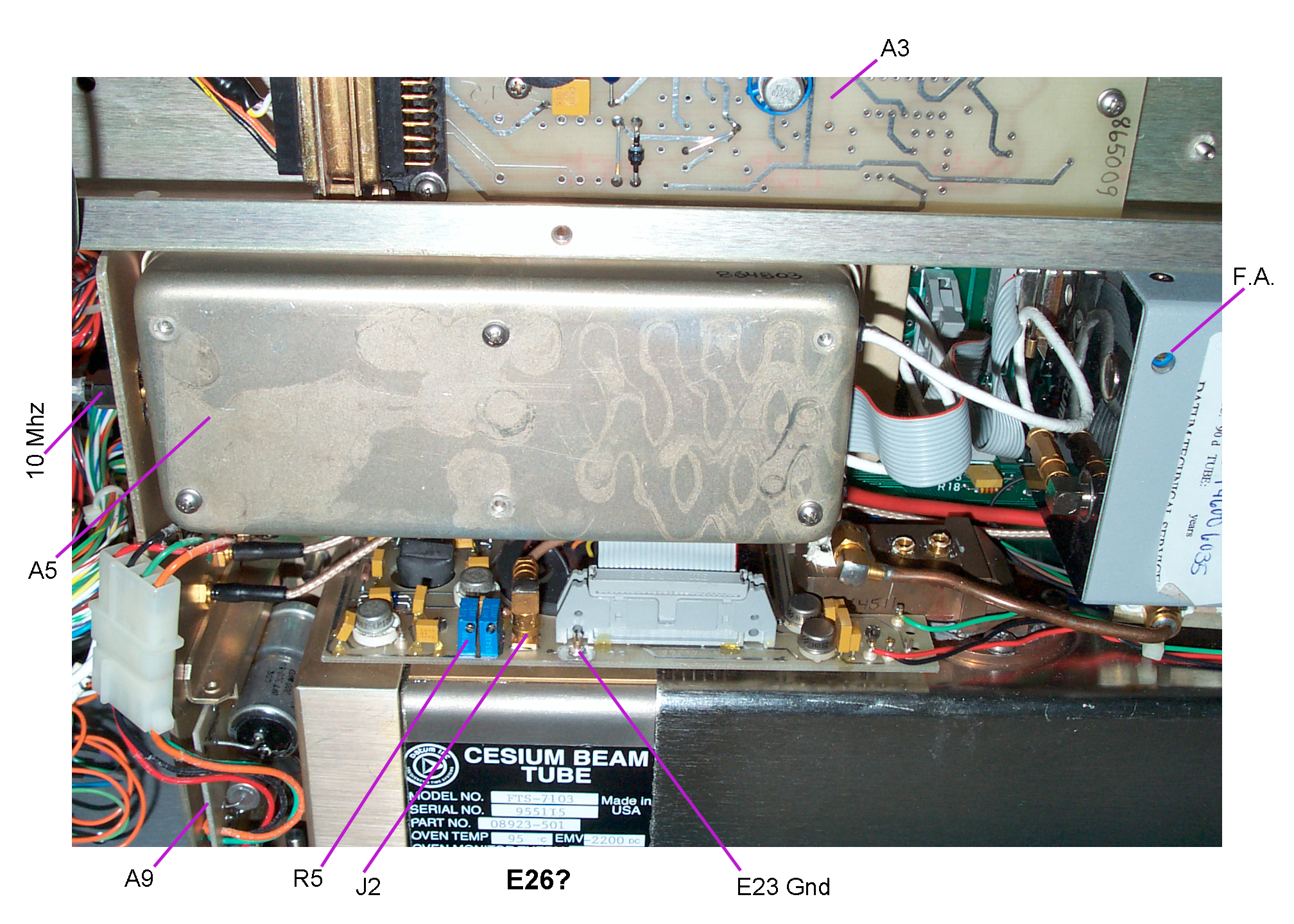 On the Cs Beam Tube Interface PCB there
are 2 10-turn pots. The one close the the SMB connector
is R9 and should not be changed. The one next to R9 is
R5 and is the manual beam current adjust. It should be
set so that the voltage between E23 (ground) and E26 (a test
point) is 1.8 +/- 0.2 VDC. But I can't find E26 on my
unit. Where is it?
On the Cs Beam Tube Interface PCB there
are 2 10-turn pots. The one close the the SMB connector
is R9 and should not be changed. The one next to R9 is
R5 and is the manual beam current adjust. It should be
set so that the voltage between E23 (ground) and E26 (a test
point) is 1.8 +/- 0.2 VDC. But I can't find E26 on my
unit. Where is it?Also note in the photo there is a small screwdriver adjustment on top of the 10 MHz OCXO that has been relocated from the front so that you do NOT need to remove the 5030 Assembly to get access to this coarse adjustment pot.
Serial Number 1013 has had the Green Lock LED on for about 3 hours. If the line cord is removed and plugged back in after 15 seconds the unit Lock LED turnes on in about 10 minutes.
NOTE
The manual implies that you
can make the loop gain or beam current adjustments on the
fly. But on the two occasions that I have tried to do
that the FTS4060/S24 gets confused. The fix has been
to pull the line plug for about 15 seconds and
restart. Without the restart the control loop is
oscillating.
Accessory
The Austron 2100T Timing LORAN-C
receiver makes a good accessory. It provides a UTC
clock, 1 PPS output and a check on the stability of the
FTS4060. Also if the reference input fails the 2100T
will break lock and need to be manually re started and so it's
a good monitor on the output of the reference source.
Data Request
If you have one of the /S24
units would you tell me if you have the 10 MHz output and your
serial number?
If you have brought a unit back to life tell me what you did. email to Brooke
If you have brought a unit back to life tell me what you did. email to Brooke
Government Liquidation and/or Shipper Warning
 When these units arrived on the truck the
pallet looked just like this photo form the Government
Liquidation auction, except that a sheet of cardboard had been
placed over the pallet and then two metal straps over
that. The FTS 4060 in the photo was never put back in
it's box! Government Liquidation should have returned
the instrument to it's box or the company that picked up the
auction items should have, but it any case complete lack of
common sense seems to have been the problem. Since this
unit (s/n 1013) was already out of it's box, it's the first
one tested.
When these units arrived on the truck the
pallet looked just like this photo form the Government
Liquidation auction, except that a sheet of cardboard had been
placed over the pallet and then two metal straps over
that. The FTS 4060 in the photo was never put back in
it's box! Government Liquidation should have returned
the instrument to it's box or the company that picked up the
auction items should have, but it any case complete lack of
common sense seems to have been the problem. Since this
unit (s/n 1013) was already out of it's box, it's the first
one tested. At first, because of the markings on the inside of the lid (dates of 1-27-88 <factory check out date>, 4MAY99, 5NOV90, 20FEB91 <user dates>) it appeared that this was not a new unit. But upon troubleshooting inside there was paper work indicting that the Cesium Beam Tube had been replaced in 1996 and so this really was an "A" condition code like new unit.
The other two units (s/n 1033 and
1227) appear to be new old stock and lock up in 10 minutes and
less than 30 minutes (was not watching when it locked).
Recommendation
If at all possible pick up
your unit rather that trust it to a freight forwarder or
other third party that may not use common sense and/or
good packaging methods.
Most of the Cesium Frequency Standard units that are being sold by Government Liquidation (and on eBay) are condition code H7 which probably means that the tube has depleted all it's Cesium and is beyond economic repair (Symmetricom wants about $ 16,000 for a replacement tube plus shipping and installation fees), so look for condition code "A" units. If buying on eBay find out if the Lock light comes on (which might take an hour or two of operation). This sometimes can be seen in the product photo. The green Lock light is the upper left most indicator.
Most of the Cesium Frequency Standard units that are being sold by Government Liquidation (and on eBay) are condition code H7 which probably means that the tube has depleted all it's Cesium and is beyond economic repair (Symmetricom wants about $ 16,000 for a replacement tube plus shipping and installation fees), so look for condition code "A" units. If buying on eBay find out if the Lock light comes on (which might take an hour or two of operation). This sometimes can be seen in the product photo. The green Lock light is the upper left most indicator.
21 Jan 2005 - By using the
manual procedure above to set the loop gain and control
voltage I have been able to get the lock LED to turn on
(and it will also do so after a power up) BUT the unit
is NOT locked and the frequency is drifting consistent
with a OCXO without any lock. So far I have not
figured out what's causing this. Be warned a Green
Lock LED may not mean the unit is operating properly.