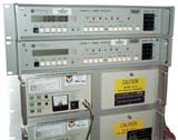
Austron 2100F LORAN-C Frequency Monitor
& 2100T Timing Receiver
©Brooke Clarke,
N6GCE2003 - 2024
2100F Frequency Monitor
2100T Timing Receiver
2084 Multifilter
2042 Simulator
1290A 24 Volt Standby Power Supply
Manuals
Patents
Pickard & Burns Model 601 Loran-C Receiver
Links
Background
The LORAN-C system was originally designed for marine
coastal navigation but has since been used for other purposes.
Aircraft LORAN-C receivers added the low cost capability to fly
directly from point A to point B. Prior to LORAN-C most
aircraft flew radials either to or from the location of a
navigation aid.
Additional LORAN-C chains were added to the central U.S. so
that users on land and on lakes could take advantage of this
precise positioning system.
Prior to LORAN-C the highest quality frequency standard in the
U.S. was the WWVB radio station on 60 kHz. There are
similar LF time stations on nearby frequencies in other
countries. Note that WWVB can be used both as a frequency
reference and by decoding it's digital time signal can be used
to set clocks and watches. LORAN-C provides a much more
stable frequency monitoring capability than can be had using
WWVB and this is the application the Austron 2100F LORAN-C
Frequency Monitor was built to serve.
The stock LORAN-C system currently does not have any digital
data containing time or date information so can not be used as a
way to set a clock. But by knowing the epoch date and time
of the LORAN-C system it is possible to know when the
synchronization point on the station being received matches the
UTC second exactly. The Austron 2100T was designed for
this Time Of Coincidence (TOC) application.
2007 - There is Enhanced
LORAN (eLORAN) experimental work going on now. Part
of this is the LORAN
Data Channel (LDC) that will add data packets to the
existing LORAN-C stations. It works by adding a new pulse
after all the existing pulses hence existing receivers
will not notice the new one. It's Pulse Position
Modulation whrere the new pulse can be shifted to one of 32
(from memory) different time slots. A bunch of these make
up one data packet. One of the data packets has the date
and time information so you could set a clock, just like you can
from GPS or WWVB. Other packets have the Lon and Lat of
the antenna and other ID info. As of June 2007 these
stations are broadcasting the Data Channel:
- Jupiter, FL 7980-Y
- Las Cruces , NM 9610-X
- Seneca, NY 8970-X
- Gillette, WY 8290-X
- Grangeville, LA 7980-Y
The stations listed below are capable of but not currently
broadcasting the Loran Data Channel.
- Middletown, CA 9940-X (* Middletown was testing the
data channel a few months ago)
- Dana, IN 9960-Z
- George, WA 5990-Y
Another aspect of the eLORAN will be a change from the current
Master -delay- Slave timing system. This way of timing made
sense in the old days since the quality of the position fix
depended on the time delays and if the master station drifted it
was not important. But as the LORAN-C stations get upgraded
to atomic standards corrected by phase micro steppers the timing
can switch to a system based on UTC. The existing single
chain LORAN-C receivers will not be affected by the change, but it
then opens up the possibility of an "All in View" LORAN-C receiver
working in a fashion similar to GPS where all the stations that
can be heard are used for the position or time fix. I'd
guess that if you throw a dart at a globe at that point you can
receive all of one chain and maybe a station or two or more from
adjacent chains, but not enough adjacent stations to get a fix
from them alone. So an all in view receiver will do better
without adding any new transmitting stations.
Frequency Transfer
The 2100F works by comparing the external reference
frequency with the selected LORAN-C station. This is done
by generating a pulse from the external reference at the GRI
rate and noting the change in the time interval between it and
the LORAN-C pulse that's being tracked. The result can be
seen either in terms of the time offset (O/FS) or as a stability
number like E12 3.1.
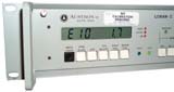
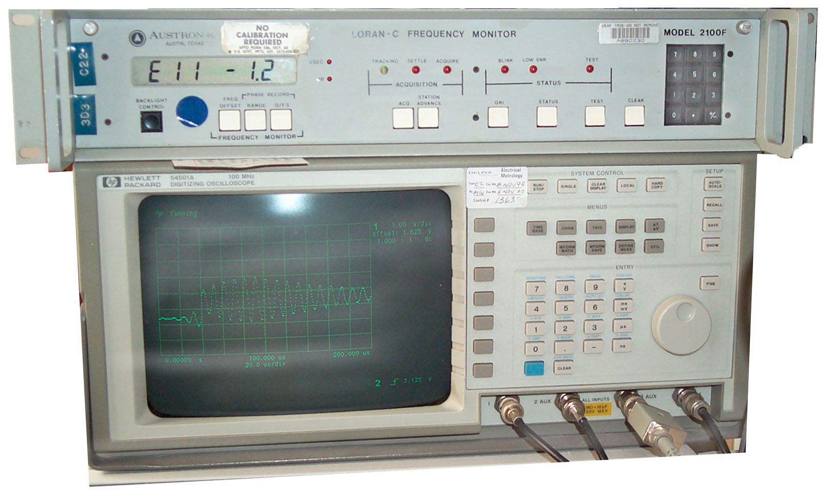
2100F Operation
This 2100F Frequency Monitor does not have a built in
oscillator and so needs a 1, 5 or 10 MHz input signal that is an
accuracy of 1E-8 or better in addition to an antenna and
power. I'm using the AMRAD active LF
whip and it works great. My Stanford
Research PRS10 GPS disciplined Rb oscillator is the source
of 10 MHz fed into the 2100F.
After letting the 2100F receive the Middletown, CA station that
is less than 1 degree of Lat and Lon from me (Status 2 Noise =
0) overnight the frequency offset displayed 1.0E-13. I
don't understand why this display jumps around to 4.0 E-12
because the phase error value (status 7) is 00.0 us.
There may be a need for the 2100F to run for some hours to
stabilize temperature in order to track properly. When
first turned on it would quickly lock on Middletown but would
not lock onto the chain master station. After a few hours
it would display something when "Advance Station" was pressed.
TDs
Whent he Advance button is pressed the display is supposed to show
the time difference between the master and the station being
tracked.
But so far it does not add up. (LORAN-C station locations rounded
to nearest second)
| me |
Master |
W |
X |
Y |
| Ukiah, CA |
Fallon, NV |
George, WA |
Middletown, CA |
Searchlight, NV |
39:11:24N
123:09:50W |
39:33:06N
118:49:55W |
47:03:48N
119:44:8W |
38:46:57N
122:29:43W |
35:19:18N
114:48:16W |
| miles @ degrees |
233 mi @ 94.8 |
570 mi @ 16.5 |
46 mi @ 127.8 |
532 mi @ 117.5 |
| code delay |
0 |
15,700 |
27,000 |
40,000 |
| emission delay |
0 |
13,796.9 |
28,094.5 |
41,967.3 |
| 2100F "station advance" delay |
0 |
15700 |
27064 |
43632 |
| delay based on known location |
1252 |
3064 |
247 |
2860 |
Station Advance - when this button is pressed a number will
appear if the 2100F has been able to see the master station pulse,
if no master station then the display will show ------. Each
time you press <1> <station advance> a new number will
appear indicating different stations could be tracked. To
change stations enter the number of stations to advance then press
station advance and the receiver will go into acquire mode.
5 May '03 - After a few weeks of rainy weather where only the
local station would lock up the receiver would not sync onto the
chain master by itself. But when <1><ACQ> is
done for a new acquisition the master and other slave stations
were found. So it appears that this must be forced manually.
The stations are now 0 (Fallon master), 27100 (Middletown),
43668 (Searchlight), and today Geroge is not there, but may show
up in a few hours.
Stations Received at 39N 123W:
chain 59900 George, WA delay 27000
chain 96100 Bosie City, OK delay 0
Gillette,
WY
delay 13032
Searchlight,
NV
delay 25400
Las
Cruces,
NM delay 41600
chain 99400 Fallon, NV delay 0
George,
WA
delay 15700
Middletown,
CA
delay 27064
Searchlight,
NV
delay 43632
Scope
By using an oscilloscope that is
triggered from the 2100F and displaying the raw received signal
you can see the quality of the signal and by using the time base
trigger delay function move the time window being viewed through
the complete GRI space. This allows other stations in the
chain to be seen. But the problem is this receiver is
designed to receive only a single station and so it's gain is set
for that station. When receiving Middletown which is very
strong the gain is turned down making it difficult to impossible
to see weak stations.
When acquiring a GRI the first time it is not clear which
station the receiver locks onto. It does not seem to always be
the master or the strongest station.
Modulation
The amplitude of the signal has some form of amplitude
modulation. It is slow and can be seen in this 1.4 MB AVI
file that lasts about 8 seconds. In my browser after
the file loads I see a still picture on a white
background. Clicking on the still plays the video.
10 Feb 2003 - I called the Middletown LORAN-C station and
asked about this and they said no modulation like that was
being done. Some time ago there was a program to add
modulation, but it was canceled for lack of funding.
This must be something caused by all my electronic equipment
or is in the Austron receiver.
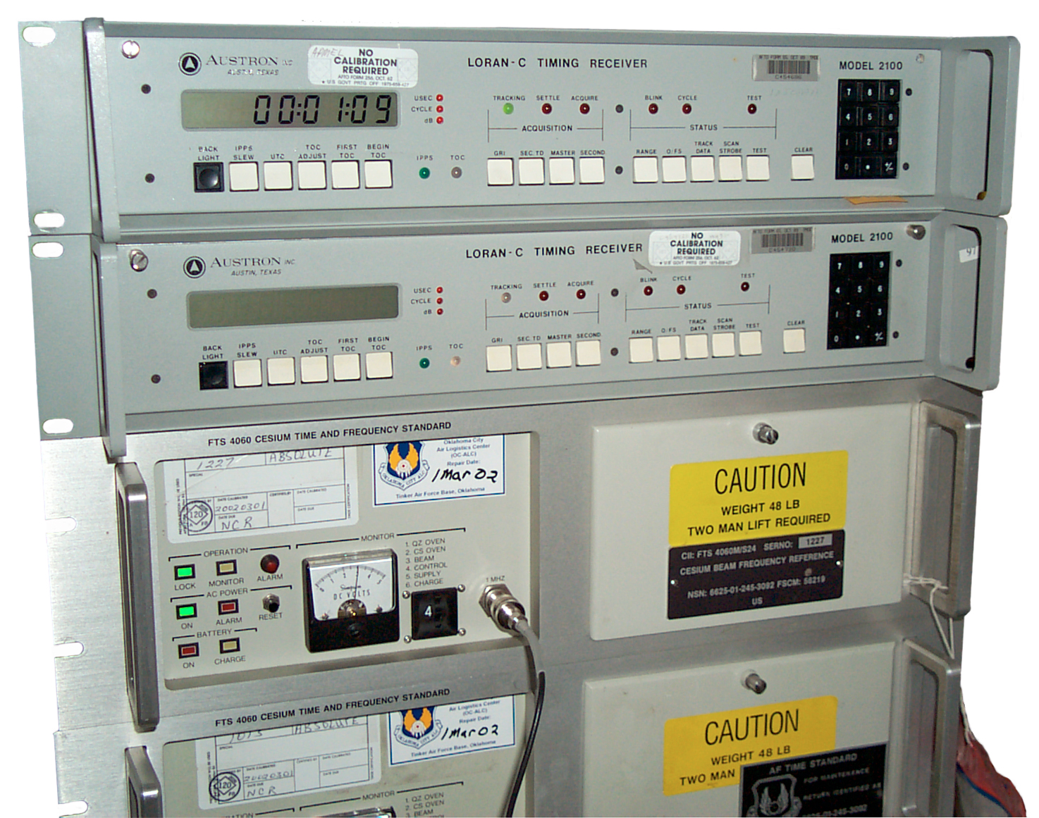
2100T Timing
Receiver
NSN 6625-01-1434-580
4 Feb 2005
Background
The timing version of the Austron
2100 receiver uses Time Of Coincidence to synchronize its 1 PPS
output with the UTC 1 PPS edge. Like GPS there are a
number of corrections that need to be made to get the edges
lined up and the manual suggests that rather than trying to
account for all of them that a visit by an atomic clock be used
to determine the offsets, not just for the current station being
tracked for for a number of stations so that they would be
available as backups.
The Stanford Research Systems FS700 Loran-C receiver does NOT
have Time Of Coincidence capability, it's more like the A2100F.
LORAN-C will survive GPS - 2024 Maybe one
station still works
When GPS became operational other
radio based navigation systems, like Omega, were shut down and
the fate of the LORAN-C system was uncertain. But in Nov.
2004 the
report
seems to indicate that the LORAN-C system will stay on the air
and be
upgraded.
It
provides
a needed backup to the GPS system for mission critical
applications like commercial aircraft landing systems.
Time Transfer
LORAN-C is a navigational system and does not send any
time codes so you can not set a clock using Loran-C. But
the whole LORAN-C system has an epoch date of 00:00:00
hours (UTC), Jan. 1, 1958. Each chain of transmitters has
a Group Repition Interval (GRI) and so the Middletown, CA
station is one of the slave transmitters in the chain with a GRI
of 9940 (i.e. the period of the group is 99.4 mS). So the
time when one of these pulses falls exactly on top of a UTC 1
second transition can be computed if you know the current time
to better than 99.4 mS in my case and you know how the total
number of leap seconds since the epoch.
The 5220333 patent widens the 99.4 mS time window by looking
at two different chains since the Time Of Concidence for both
chains will be much larger than for a single chain.
5220333
Method and apparatus for determining universal coordinated
time from Loran-C transmissions, Bruce
M. Penrod, Austron
Inc, 1993-06-15, - many related
interesting patents
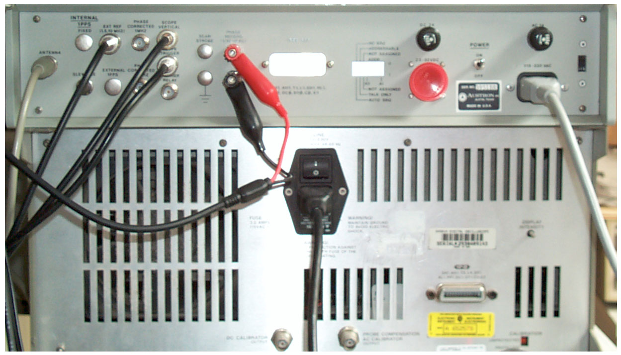
Setup
Tracking
Open front panel and set toggle switch to 1, 10 or 5 (left to
right) to match reference frequency. (if this is not done the
Tracking LED may blink Red and Green). Then connect to:
Key in the desired GRI (in my case
99400) and press "GRI".
Key in 1 and press Master.
Now the Acquire red LED turns on for awhile, then the Settle red
LED for awhile, then the green Tracking LED is on.
At this point pressing "Track Data 8" will show "--E-----"
indicating that the TOC has not yet been set.
Note the receiver is now tracking the master station for the
entered GRI.
Time Constant
At this point I set the time constant to the longest possible
value (0 Track Data 6) which is 3200 GRIs.
15 Feb 2005 - With the Time Constant set to 3200 GRIs I changed
the C Field on the FTS4060 from 525 to 580, maybe a change of
5.5E-13 to 1.1E-12 and the Tracking LED started blinking
alternately Red and Green. Pressing <1>
<SECOND>ary relocked the receiver to Middletown in about 8
minutes.
Slave Station
Now by entering the Total Emission Delay for the salve station
(Middletown in my case is 28000 us) and pressing SEC TD to set
the value, then key in 1 and press SECONDary to lock to that
station. In my case it took 8 minutes to lock up.
After the green Tracking LED lights the display is showing
the actual emission delay, in my case 27072. This can be
brought back by pressing the SECONDary key. Doing the
slave lock also disables TOC tracking so it needs to be re
synchronized.
If the receiver is tracking a secondary station and you
press the MASTER button the display will show "--------", and
when you press SECONDary the display will show the total
emission delay, in my case ""27026 ".
Tracking LED
This LED is green when tracking a station. It slow blinks
Red and green when the receiver can not track the local
reference or it has seen a signal strength change of 10 or more
dB. This will happen if there is no local reference
connected or if the local reference is drifting too fast for the
Time Constant that has been set.
For a signal strength change the Red-Green can be reset to
steady green by pressing 0 then Track Data then 8.
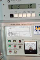
Ref Freq Offset
Just after TOC
lock in photo at left the stability is shown as E10 1.7.
The offset of the local reference can be displayed by using
Track Data 4 which now is E12 9.4. 8 minutes later the
display is E12 8.6 and it appears to be working it's way to
lower numbers. The minimum delta time interval measured
for the Track Data 4 stability display is 0.01 uS (see this by
pressing O/FS). Thus to see 1E-14 would take 1E6 seconds
or about 11.57 days. This is where GPS with a 1 PPS
accuracy on the order of tens of nanoseconds has a big
advantage.
The next morning (about 18 hours running time) the Track Data 4
shows E13 3.7 but waiting more days the best it gets is in the
3E-13 area, maybe that's as good as the FTS4060 is set?
By pressing <0>, <Track Data>, <7> the O/FS
value will be reset to zero. Only zero can be set, not
other values.
This is a good thing to do when adjusting a frequency standard,
like the
FTS4060 Cesium, when
a new setting has been made.
Note
LORAN-C may be as good as GPS
for precision time transfer, and may have advantages over
GPS.
 1.0E-13
Limit
1.0E-13
Limit
There seems to be a limit of 1.0E-13 in the 2100T. It may
be that my
FTS4060 never gets any
better, but I think that's not the case. For example the
stability should drift into and out of the 1E-14 area, but the
2100T never shows anything better than 1.0E-13. If you
have seen better numbers let me know.
TOC
In order to set the internal clock
an external 1 PPS input is needed that's within one GRI (and
ahead of the second tick). Or the slewable 1 PPS output
can be connected to the EXT 1 PPS input, which I did for
convenience. Then the next TOC is keyed in and First TOC
pressed to load it. Then 1 is keyed in and Begin TOC
pressed. At this point the TOC LED will alternately flash
red nad green and when the TOC time occurs if all is well the
TOC LED turns solid green.
Once the TOC has been set, the second prior to a new TOC the TOC
LED turns red then if the internal 1 PPS edge is aligned with
the LORAN-C TOC the LED turns green again.
At power up the green 1PPS LED will have a random timing.
Because of this it's impossible to set the UTC to within one
GRI. But when an external 1PPS is input to the 2100T and
an attempt is made to set the TOC, although the TOC setting
fails, the green 1PPS LED is now synchronized to the external
1PPS thus allowing the UTC to be set. The next TOC setting
procedure will then work.
22 Apr 2005 - When using an external 1 PPS that's good, like
from a GPS receiver, if you set a random time for First TOC and
try to sync, it will NOT sync. I tried this to get the 1
PPS in sync, but it didn't work, so now need to use an actual
TOC to resync after a big sferics crash.
Once the receiver has the TOC locked it automatically computes
when the next TOC will occur. You can see it by pressing
FIRST TOC (without first pressing 1). One second prior to
a TOC the TOC LED will turn red then at the TOC back to green.
Track Data
Pressing <Track Data> <n> will display the Track
Data value.
Pressing <some number(s)> <Track Data> <n>
will set the Track Data Value.
Sometimes only zero is a valid input number.
Track
Data #
|
Function
|
0
|
Enable
Front Panel
|
1
|
Lock
Front Panel
|
2
|
Signal/Noise
4 = 9 dB
28 = 0 dB
224 = -12 dB
3584 = -21 dB
|
3
|
Receiver
Gain
in dB
|
4
|
Frequency
Offset
|
5
|
Cycle
number being tracked (S.B. 3.0)
|
6
|
Receiver
Time
Constant
0 = 3200 GRIs
1 = 1600 GRIs
2 = 800 GRIs
3 = 400 GRIs
4 = 200 GRIs
|
7
|
Accumulated
phase
shift (same as O/FS)
|
8
|
Receiver
Status
MSB to LSB
E = acquisition Mode
E = TOC LED red
E = No TOC Sync
E = loss for reference
E = LORAN-C Blinking
E= tracking cycle more than 0.5 from 3.0
E= gain change > 10 dB
E = not tracking
|
9
|
Delta
TIme Internal fixed - External 1 PPS
|
O/FS Button
Pressing O/FS (Offset) causes
the LCD to show the difference between the local reference and
the LORAN-C derived 1 PPS. This receiver was designed
for use with lab grade crystal oscillators and so the display
can go to thousands of microseconds with a LSD of 10 nano
seconds. The minus sign is all the way to the left of
the display and so can easily be missed when the display is
something like 0.03.
IEEE-4388
Both of these receivers have the IEEE-488 option.
Two 2100T receivers arrived in the
same jiffy box from a Government Liquidation auction. They
were sold as condition code A1 (new) units and included a couple
of manuals. One unit had the left front handle bent inward
which prevented the front panel from hinging down and is missing
the right side panel attachment captured screw (since replaced
with part from RAF). It was DOA. The other unit
looks nice on the outside.
After re-seating the LCD module in the bent handle unit and
plugging in the front panel ribbon cable the unit operates
properly. The nice looking unit still has some type of
electrical problem.
7 Feb 2005- Board swap troubleshooting
Moving the microprocessor board from the bad receiver into the
good receiver causes the good receiver to show the same power up
error (does not end up in time mode) as the bad receiver.
This means that there's something wrong with the microprocessor
board.
But moving
the microprocessor board from the good receiver to ge bad
receiver also has the same power up error.
Why? Still a mystery since there was a
bad IC on the microprocessor board, unless the loose screw &
washer were causing a problem.
A short 2-56 screw and a #2 lock washer were found loose in the
bad receiver. Came from front panel PCB.
The large PCBs have edge connectors with 43x2 contacts.
With the front panel facing you looking down on a PCB the
contacts are numbered /Y to A (left to right) The letters are:
ABCDEFHJKLMNPRSTUVWXYZ and then again except with a bar over the
letter like /A /B.../Y (no /Z). The contact directly below
A is 1 and below /Y is 43.
The manual uses signature analysis as a trouble shooting method,
so I have an
HP 5004
Signature Analyzer and will be shortly testing the non working
unit.
1 March 2005 - Replaced U4 (74LS244) that the 5004 identified as
bad and now the receiver powers up properly ending in the time
display mode.
2 March 2005 - the repaired receiver is working just like the
other one. The
HP 5004
Signature Analyzer pointed out the bad IC. If you have an
Austron 2100F or 2100T (or any equipment documented to use it)
the Signature Analyzer is a good investment.
Some other possible front panel related problems from Chuck
Harris:
- The 1 uF tantalum caps (C2 and C5) on the front panel PCB
may need to be replaced if each key press is causing
bounces.
- The LCD may have a poor connection between the pins and
frame. But first try reseating it. This should
be a stock part, but need to find it.
- If the +5 supply regulator is bad and the voltage gets to
around 5.5 V the LCD will become erratic.
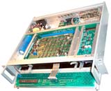
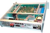
The 3 large
PCBs plug into a bus and any one of them can be moved to the top
or bottom position to get easy service access without using an
extender card.
The 2 RF amplifiers (small PCBs) also are on a bus so one of
them can be moved to the top for alignment. The bottom
small PCB 9DAC card) is always in the bottom slot.
2084 Multifilter
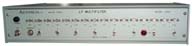
The LORAN-C frequency of 100 kHz is surrounded by
high power military digital radio stations. By filtering out
these stations the interference they cause can be reduced.
There is also a
Sferics
warning lamp on the front panel. Filter #2 (they are
numbered right to left when looking at the front panel) has a
"peak" function. The idea is to tune filter #2 for the
maximum interfering signal and then tune one of the other filters
to be on that frequency.
The A.C. power input connector looks like a standard american 3
prong plug recessed in a cylinder, so a special line cord is
needed for power. Made from an extension cord by cutting off
a small nub.
Here is a 0 to 200 kHz
spectrum
display with the output from both the DA-100 and the AMRAD
active whip antennas. You can see that there are a number of
adjacent signals stronger than my local LORAN-C station.
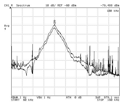
After using the HP 4395A in both spectrum and network analyzer
mode the filters were set and a comparison spectrum plot from 60
to 160 kHz was made. The upper trace is w/o the filters set
using rear panel switch. The lower trace is with all filters
set except number 2.
The Loran-c "triangle" has a peak (-80 dBm) that's maybe 50 dB
above the noise floor (-130 dBm) becasue the Middletwon station is
very close to me. The RTTY station at 132.625 has been
depressed by about 30 dB.
When testing in N.A. mode any power level higher than -24 dBm
caused the Sferics lamp to turn on, so N.A. testing was done at
-30dBm.
The station at the very left side (60 kHz) is WWVB-C.
I'm using the 2084 as an antenna multicoupler driving a couple of
2100T receivers with the filters turned on. I've noticed
that the Sferics white lamp flashes every now and then.
I notice that the green 1 PPS LEDs on the two receivers are not
flashing at the same time, need to figure out how to synchronize
them, i.e. get them correct. This has been done, see TOC
above for procedure.
Friday 22 April 2005 4 pm PDT N. Calif.- It's been high overcast
most of the day and the Sferics lamp has been flashing and
sometimes double flash. Both 2100T receivers went into
alternate red-green TRACK mode. Pressing 0 - <Track
Data> 8 cured the top 2100T, but the bottom receiver (has the
top receiver's output as it's input) lost lock and would wasn't
fixed by 0 - <Track Data> 8. These problems are almost
certainly being caused by Sferies. Sometimes the Sferies
lamp is flashing within seconds of a prior flash. Maybe
there's going to be a lighting storm? The forecast is for
rain tonight and maybe thunder storms tomorrow. So there's
probably a thunderstorm going on now that causing the
Sferics. The status indication was that the gain had changed
by more than 10. I'm very close the the 99400 station at
Middletown (normal gain 40) and so the sferic must have been very
strong to cause the gain (88) to change.
This appears to simulate a master
station and two salve stations. Although it has a whip
transmitting antenna the signal strength must be very feeble, only
enough to drive a very nearby receiver. Thumbwheel switches
to set the GRI and emission delay for each slave.
Manual or
any info wanted for the 2042.
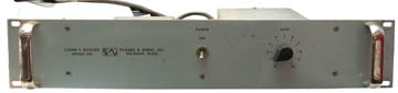
1290A 24 Volt
Standby Power Supply
This is a battery backup supply for
24 volt timing instruments. And for many years they have
been 24 volt units.
LORAN-C Receivers
Lorchron LORAN-C Timing
Receiver LFT-504
Micrologic SportNav with
MGRS - hand held with military MGRS cooridnates
PSN-6 - attaches to PRC-25 or PRC-77 military back
pack tranceiver
LORAN-C Spectral Lines
If you tune in the 135.7 - 137.8 kHz
range you will find spectral lines coming from LORAN-C
stations. The lines depend on the GRI of the station and
have been complied at:
Loran
Lines
Visible in North America For my local station at
Middletown, CA 9940 they are:
135,699.195, 135,704.225, 135,709.256, 135,714.286, 135,719.316,
135,724.346, 135,729.376, 135,734.406, 135,739.437, 135,744.467,
135,749.497, 135,754.527, and many more.
Here is a
4395A Spectrum Analyzer plot of 135.7 -
137.8 kHz showing maybe 36 loran-c spurs. This is using the
AMRAD LF active whip antenna mounted at
ground level.
The marker peak serach finds the largest one at 137.6005 kHz and
the list shows one at 137,600.604
Next peak search finds 136.8445 kHz at -122.56 dBm, but they are
all about the same magnitude and so the peak jumps around.
The noise floor between peaks is about -139.45dBm/root Hz.
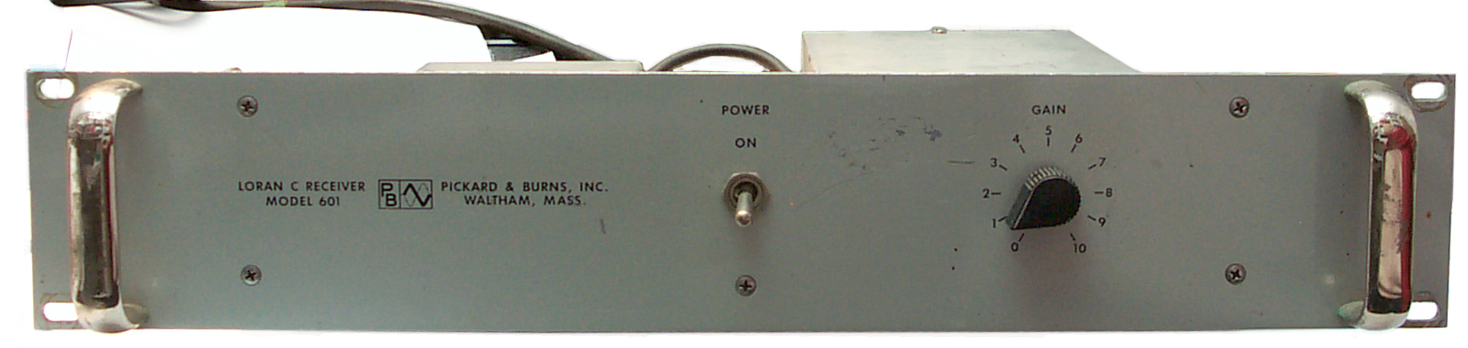
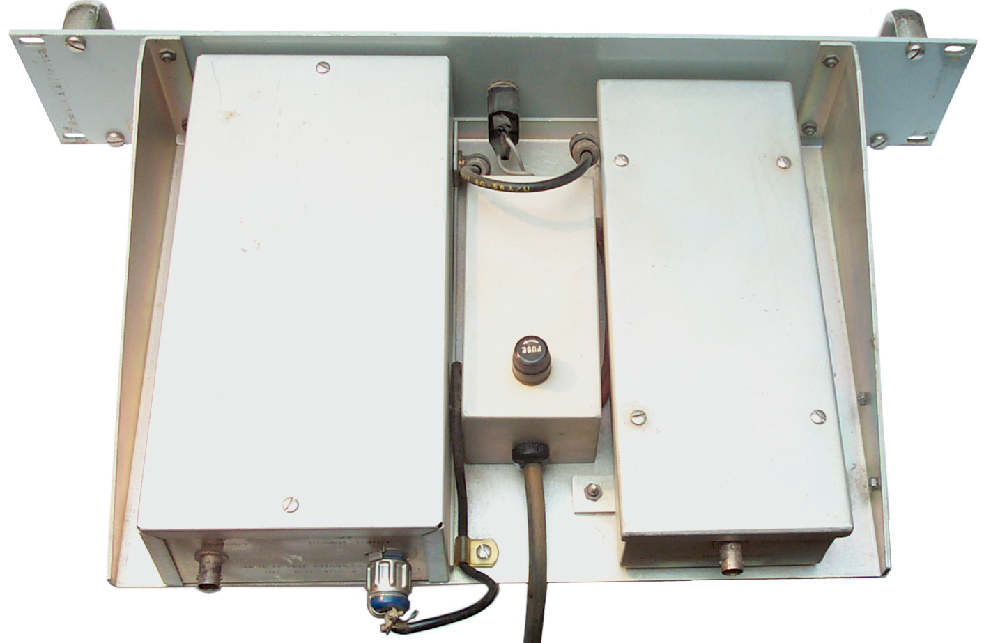
Pickard & Burns Model 601 Loran-C
Receiver
|

|
Front
|
Back
|
This receiver, as is typical of LORAN-C receivers, has no frequency
conversion circuitry. The RF is filtered and amplified and
comes out the output separated from adjacent signals centered at 100
kHz. The functional boxes are:
- Preamplifier 601-10 for 102" whip
- Receiver 601-20
- Power Supply
The Preamp did not come with the receiver and power supply.
There are two options:
- Use my existing AMRAD active whip
This has the advantage of simplicity
- build the P&B amplifier and use with a 102" CB type whip
This may be a better solution for a LORAN-C only receiver since
it contains some filtering.
The manual was included that has schematics and parts lists.
My interest is in looking at the new 9th pulse that
contains data. This would make a nice front end for a micro
controller based data decoder. Maybe not as nice as the
Austron 2000 series front end, but better than some others.
LeapSecond.com - Museum - Austron
2100 Loran-C Timing Receiver - Austron
2100F
start procedure - Loran-C
by oscilloscope (unfinished) - 9940 TOC
-
LoranView
by DF6NM - Listening to all the worlds LORAN-C stations from
Nuernberg
Manuals
A CD-ROM with the following
Austron manuals is available. For ordering information see
the
product page.
1120 Oscillator (octal tube base) brochure & drawing 3 pg
1210D Clock stiched, rotated, cleaned. 130 pg (prior to
stiching more like >200 pg
1250 Frequency Standard. 33 pg
1250A Frequency Standard. 52 pg
1250B Frequency Standard. 51 pg
1290A Power Supply 57 pg
2000C Analog Loran-C receiver. Good overview of Loran-C and
how a receiver works. 253 pg
2010B Disciplined Oscillator - locks to an external reference 105
pg
2042 Simulator - a Master and two Slave stations make up a chain
direct and antenna outputs 67 pg
2084 Filter & Multicoupler - also has Sferics lamp, great for
feeding multiple Loran-C receivers 54 pg
2100F Loran-C Frequency Monitor uP based- includes Signature
Analysis data 166 pg
2100R Loran-C Frequency Monitor 168 pg
2100T Loran-C Timing Receiver uP based includes locking to Time of
Coincidence, S.A. test data 225 pg
Brochure of Austron Products 8 pg
Patents
5220333 Method and apparatus for determining universal
coordinated time from Loran-C Transmissions,
Bruce M. Penrod, Jun 15, 1993,
342/389; 368/47
4839613 Temperature compensation for a disciplined frequency
standard,
4740761 Fine
tuning of atomic frequency standards, Barnes; James, Rodrigo;
Enrico, April 26, 1988, 331/3 ; 331/94.1,
4314378 Antenna low-noise Q
spoiling circuit,
Clarence
W. Fowler, Bruce
M. Penrod (Tractor,
Inc.), Feb 2, 1982, 455/291, 455/292 -
An input coupling circuit for detuning the Q of a high-Q
ferrite rod antenna is disclosed. A high-impedence low-noise
amplifier is used to amplify the output signal from the LC
resonant tank of the rod antenna. A portion of the amplified
signal is fed back directly into the magnetic circuit of the
antenna tank. This negative feedback reduces the losses produced
in the magnetic circuit due to the presence of nearby conductors.
As a result of this reduction, an increase in the antenna
sensitivity and a decrease in the cross-feed from other nearby
antenna is produced.
| Cited Patent |
Filing date |
Publication date |
Applicant |
Title |
US1907653
|
Feb 21,
1930 |
May 9,
1933 |
Telefunken Gmbh |
Short wave receiver |
US2641704
|
Aug 3,
1950 |
Jun 9,
1953 |
Rca Corp |
High-inductance loop
antenna and system |
US2774866
|
Jan 30,
1956 |
Dec 18,
1956 |
Emerson Radio &
Phonograph Cor |
Automatic gain and band
width control for transistor circuits |
US2787704
|
Apr 19,
1955 |
Apr 2,
1957 |
Philips Corp |
Constant band-width input
stage with high q antenna |
US3005093
|
Sep 16,
1960 |
Oct 17,
1961 |
Avco Mfg Corp |
Transistorized detector
and automatic gain control circuit |
US3077562
|
Jan 7,
1960 |
Feb 12,
1963 |
Key Lee P |
High gain radio receiver |
US3479609
|
Jun 13,
1966 |
Nov 18,
1969 |
Us Army |
Attenuation circuit using
a tuned amplifier whose q is varied by shunting resistors |
US3495031
|
Nov 1,
1967 |
Feb 10,
1970 |
Zenith Radio Corp |
Variable q i.f. amplifier
circuit for a television receiver |
US3510807
|
Sep 29,
1966 |
May 5,
1970 |
Us Navy |
Electronic switch using a
series string of two diodes,one zener and one
conventional,and a capacitor in parallel with a resonant
circuit as a q spoiler |
US3528023
|
Aug 29,
1968 |
Sep 8,
1970 |
Gen Dynamics Corp |
Amplifier |
US3673523
|
Oct 5,
1970 |
Jun 27,
1972 |
Electrohome Ltd |
Signal translating
networks and control circuits for the tuners of signal
receivers |
US3786363
|
Jan 5,
1973 |
Jan 15,
1974 |
Us Navy |
Voltage-controlled
low-pass filter |
| Citing Patent |
Filing date |
Publication date |
Applicant |
Title |
| US4414690 * |
Jun 15,
1981 |
Nov 8,
1983 |
U.S. Philips Corporation |
Active aerial |
| US4442434 * |
Mar 13,
1981 |
Apr 10,
1984 |
Bang & Olufsen A/S |
Antenna circuit of the
negative impedance type |
| US4805232 * |
Jan 15,
1987 |
Feb 14,
1989 |
Ma John Y |
Ferrite-core antenna |
| US4996484 * |
Dec 29,
1988 |
Feb 26,
1991 |
Atlantic Richfield Company |
Method and apparatus for
cancelling powerline noise in geophysical electromagnetic
exploration |
| US6809694 |
Mar 27,
2003 |
Oct 26,
2004 |
Andrew Corporation |
Adjustable beamwidth and
azimuth scanning antenna with dipole elements |
| US6963314 |
Sep 26,
2002 |
Nov 8,
2005 |
Andrew Corporation |
Dynamically variable
beamwidth and variable azimuth scanning antenna |
| US7158049 * |
Mar 24,
2003 |
Jan 2,
2007 |
Schlumberger Technology
Corporation |
Wireless communication
circuit |
| EP0392327A1 * |
Apr 4,
1990 |
Oct 17,
1990 |
Texas Instruments
Deutschland Gmbh |
Damping circuit for the
antenna resonance circuit of a radio transmitter-receiver |
| EP2541680A1 |
Jun 26,
2012 |
Jan 2,
2013 |
Roke Manor Research
Limited |
Reduced Q low frequency
antenna |
| WO1993001658A1 * |
Jul 6,
1992 |
Jan 21,
1993 |
Electronic Advanced
Research Ltd |
Radio receiving circuits |
| WO2002093687A1 * |
May 13,
2002 |
Nov 21,
2002 |
Commissariat Energie
Atomique |
Antenna quality factor
self-adaptive device |
Links
Table of US LORAN-C Stations
Patents related to Disciplined
Oscillators -
USCG - LORAN-C
- Signal
Specification - just U.S. LORAN-C - History
page -
U.S. Naval Observatory - Time Service Department - LORAN-C Timing
Operations - LORAN
Times of Coincidence on line computation
International Loran Association
- Links
Hyperbolic
Radio navigation Systems by Jerry Proc VE3FAB
NTP use
of LORAN-C -
SDR in action: The last
LORAN-C receiver -
Locus - modern "All In View" (i.e. 40 stations) Loran-C receivers -
SDR in action: The last
LORAN-C receiver - A $20 LF Loop
antenna -
Loran-C
Challenges
GNSS:
From a Quarter Nautical Mile Down to Meter-Level Accuracy -
The
Case
for
e-LORAN by the UK
All these have extensive
bookmarks and the instrument manuals have a supplement with color
photographs including inside.
Back to Brooke's PRC68, Products for Sale, Time & Frequency, Electronics, Navigation,
Position
&
Orientation, Military Information,
Personal Home
This is the [an error occurred while processing this directive] time
this page has been accessed since since 8 Feb 2003.
 Just after TOC
lock in photo at left the stability is shown as E10 1.7.
Just after TOC
lock in photo at left the stability is shown as E10 1.7.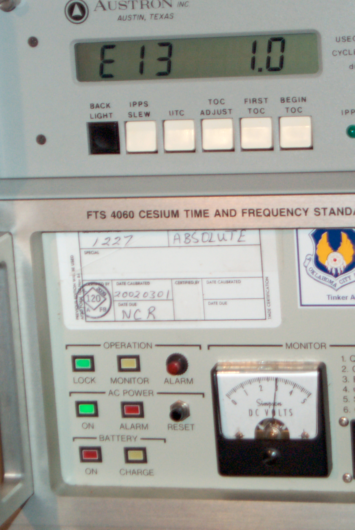 1.0E-13
Limit
1.0E-13
Limit But moving
the microprocessor board from the good receiver to ge bad
receiver also has the same power up error. Why? Still a mystery since there was a
bad IC on the microprocessor board, unless the loose screw &
washer were causing a problem.
But moving
the microprocessor board from the good receiver to ge bad
receiver also has the same power up error. Why? Still a mystery since there was a
bad IC on the microprocessor board, unless the loose screw &
washer were causing a problem.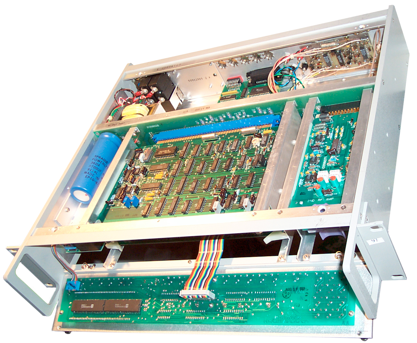 The 3 large
PCBs plug into a bus and any one of them can be moved to the top
or bottom position to get easy service access without using an
extender card.
The 3 large
PCBs plug into a bus and any one of them can be moved to the top
or bottom position to get easy service access without using an
extender card.