O-1814/GRC-206 Reference Frequency Oscillator
Rubidium Frequency & Time Standard
© Brooke Clarke 2007 - 2015
 |
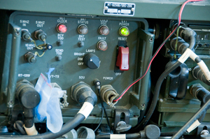
in MT-6250 Rack.
Note Set Clock is red because the time has not been set.
|
Background
Info Wanted
Front Panel Controls, Indicators & Connectors
Label
Inside
Connectors
Operation
Theory of Operation
Outputs
Time Of Day
Have Quick
Backup Battery
M-100 Rubidium Standard
Disassembly
Manuals
Modification Ideas
Links
Background
The
GRC-206
Pacer
Speak system optionally uses a master frequency standard,
the O-1814. This system is composed a
MT-6250 rack holding radios for HF, VHF
and UHF all of which are linked to a common control panel.
The control panel can be located at the end of a 3 km fiber optic
cable. Two independent control panels can be used if the
operators don't try to use the same radio. The
URC-113 is the HF radio system
that uses a
PRC-104 but with a higher
power
AM-71148 RF amp.
The front panel has pushbuttons for Receive and Send Time Of Day
which means it has an internal clock so it's both a frequency and
a time standard. Precision time is needed for modern
frequency hopping military radios. The RT-1319 UHF radio
needs the TOD as well as the
SINCGARS
VHF low band radios like the
RT-1439
or RT-1523.
I think the reason for using a Rb frequency standard in this
system while you don't see them in Army SINCGARS installations is
the need for UTC accurate TOD for this application. In the
army application the net controller can set the TOD and download
that time into all the netted radios. Even if the net
control time is wrong all the radios will
interoperate. But when an aircraft is inbound from
someplace far away (the TOD on the aircraft was set at it's home
base) the TOD of the aircraft and the Pacer Speak system need to
be the same for the radios to interoperate.
The inspection stamp on the Rubidium standard is 8311.16 which is
week 11 of 1983. This predates the Gulf War and the
introduction of GPS into large scale military operations.
STANAG 4430 was started in 1988 so was not the source of the TOD
protocol. But the elements of 4430 look like a good match,
they are:
- 1 PPS signal
- Standard Time Message (STM)
- Extended Have Quick Message (XHQ)
- an optional 5 MHz signal.
- bi-directional interface is supported. An equipment
can both receive and send the TOD.
The TSQ-198
Tactical
Terminal
Control System (TTCS) photo on the FAS web page does not
show the O-1814 installed in the rack. So the later versions
probably replaced this reference with a GPS time fix?
An email from a GRC-206 user said [my comment]:
"The premise was this. Lets say
the radio system was about to go down, for what ever reason
(like the generator was about to die or whatever). Theory was
that you could take the HQ time from your UHF radio and pump it
across and the RFO [O-1814 Reference Frequency Oscillator] would
hold onto that time while you got the radio system back online.
That was the theory anyway.
Our experience was that it would hold a valid time for about 15
minutes and then die. My watch kept better time. Sooooo, what we
did instead was just take the RFO out and put it in the conex
and use the hole to mount either a TV set, paperback books or
some other such stuff. The RFO was a total waste of our time and
effort as far as we could tell." -Charlie-
As for the RFO, it was crap from the day we got it.  As big as it was it couldn't keep accurate time for more than 15 minutes.  Supposedly it was some big scary crystal time system in there.  My PRC-117F keeps very accurate time with its keep alive and keep it for days.  Something was just never right with the RFOs
-Charlie-

This suggests it was not a backup battery problem but rather a functional problem.  I'll check it when the Polaris GPS receiver arrives to allow loading the Have Quick time into the RFO.
This unit would keep very accurate time when running but when the
external power fails it falls back on it's internal
batteries. Charlie's comment ...15 minutes and then die."
seems to be saying it quit working, not that it had the wrong
time. More below in the
Backup Battery
section.
The GRC-206(V)3 system is the only one of the first four versions
(V)1, (V)2 and (V)4 did not use the O-1814) that used the
O-1814. (V)1 had crypto but not Have Quick (ECCM) and (V)2
and (V)4 did not have either crypto or Have Quick.
The O-1814 was designed specifically for the GRC-206 system.
So the presence of a 5 MHz output seems to suggest it's there to
feed the 5 MHz reference frequency input on the AM-7148 that sends
it to the synthesizer in the RT-1209 to put the HF radio exactly
on frequency. The documents that are specific to the RFO
aspect of the system don't show any cable between the RFO and
AM-7148. Why? Was it an oversight, or not needed, or didn't
work, or . . . If you know
please
tell me?
The 5 MHz output can be phase locked to the optional 5 MHz
input. The testing procedures for the RFO contain checks to
see that this works. But the only input source that would
make sense would be a Cesium Frequency standard, like the
FTS4060.
This may have been part of a way to confirm the quality of the
Rubidium standard in the O-1814 or some other unknown reason.
The O-1814 is supplied DC power when there is DC power on either
the Vehicle or Aux input connectors to the GRC-206 system.
Turning off the master switch on the
Power
Distribution Unit does not turn off power to the O-1814.
I've been told that the O-1814 was also used in the GRC-215.
WANTED
Manuals or any information about
this unit. Please
email me
with whatever.
I have received:
T.O. 31R2-2GRC206-1-1 Supplemental Operators Manual AN/GRC-206(V)3
T.O. 31R2-2GRC206-2-1 Supplemental Maintenance Instructions
AN/GRC-206(V)3
both of these are mainly concerned with the O-1814 and are
probably all the documents about it.
Front Panel Controls, Indicators &
Connectors
There is no rear panel, all controls
and indicators are on the front panel.
5 MHz In: BNC-f
5 MHz Out: BNC-f
Set Clock: Lamp
Batt Status: Lamp
Cold Osc: Lamp
Ext Power: Lamp
10 MHz Out: BNC-f
Rcv TOD: Pushbutton (Time Of Day)
Send TOD: Pushbutton
Bright, Dim, Off: rotary switch
Fault: Lamp
Reset: Hooded switch (braker?)
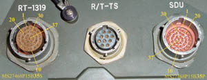
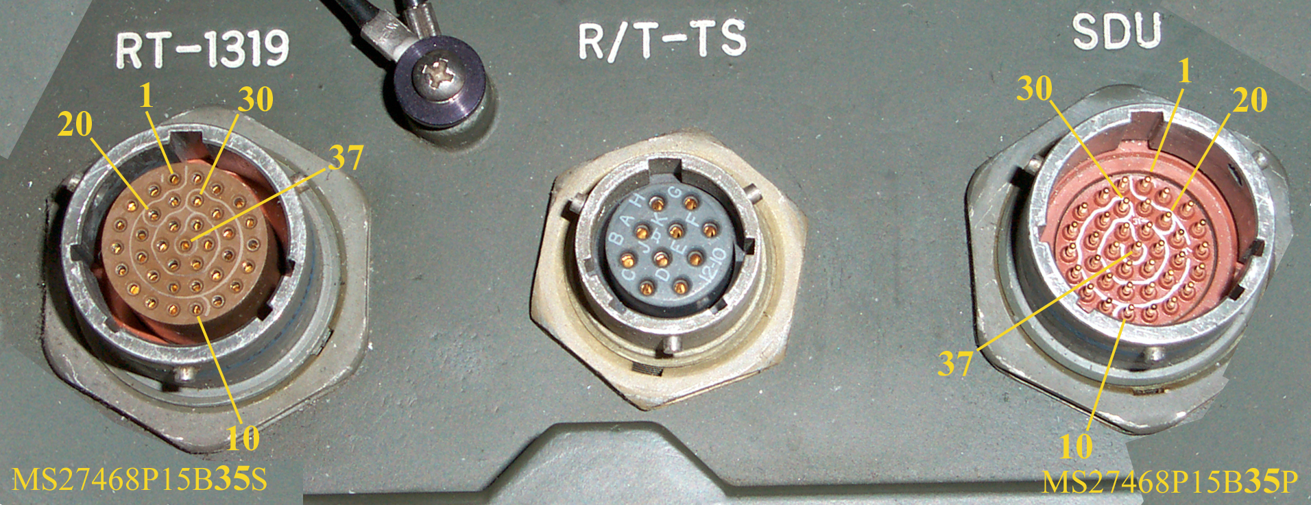
RT-1319: MS27468-P15B-35S connector (the
RT-1319 is the Have Quick UHF radio)
The p/n says 35 Sockets, but I count 37 sockets?
R/T-TS: 12-10S connector (purpose?) guess R/T =
Receiver/Transmitter TS = Test Set
SDU: MS27468-P15B-35P connector - SDU = Signal Distribution Unit
C-11166
The p/n says 35 Plugs but I count 37 Plugs?
POWER: 12-3P connector mates with KPTO 6F12-3S
There are two VRC-83 air band radios in the GRC-206 system.
But only one of them can be cabled to this time/frequency
standard. It's not clear how the other radio gets it's
TOD. If this was a just a frequency standard then it would
not have all the extra expense of the Time Of Day functionality.
R/T-TS Connector
Pin
|
Function
|
A
|
+5 V Out
|
B
|
TOD Out
|
D
|
800 kHz Out
|
E
|
800 kHz Retrun
|
F
|
TOD In
|
G
|
Ground
|
H
|
Ext 800 kHz Enable
|
J
|
TOD Continuous
|
Why the 800 kHz?
Let me know
Label
O-1814/GRC-206
Ser: AE0054
FO4606-81-C-0017
707243-801
MFR: 37695
Magnavox, U.S. Ft. Wayne, MO.
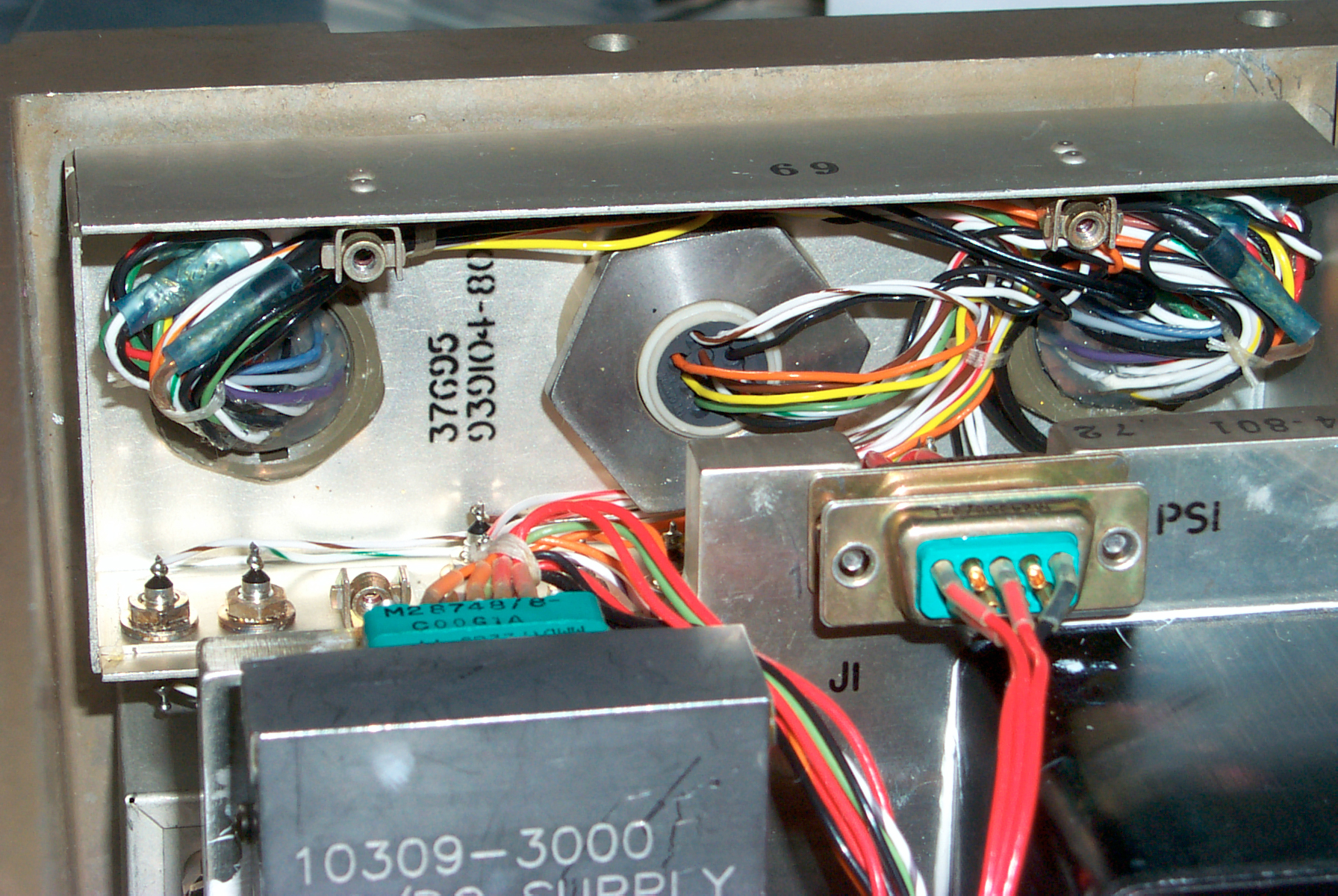
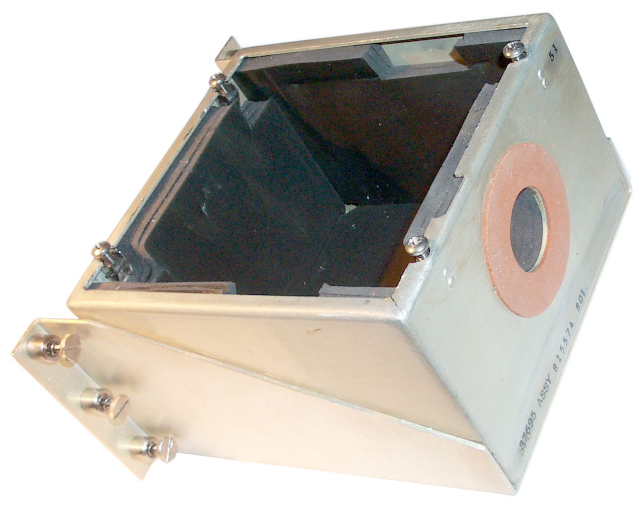
Inside
The bottom cover comes off using a #
2 Poz drive and the screws are captured to the cover. The
bottom cover has a plug in case the batteries "vent".
 The lower left box with
the orange circle is the battery box. It's held in by 6 thumb
screws that have slots for a long blade screwdriver. The 9 pin
D-sub connector only has Red, Black and white wires connected.
The lower left box with
the orange circle is the battery box. It's held in by 6 thumb
screws that have slots for a long blade screwdriver. The 9 pin
D-sub connector only has Red, Black and white wires connected.
Above it is the Efratum M100 Rubidium Standard.
Below the M100 is the "A2" PCB with a bunch of wires from it's
socket going to the front panel. There are three coax cables
to this board. Probably the 5 MHz in, 5 MHz out and 10
MHz. One of the boxes on the back of the front panel may
take in the 10 MHz M100 output and has a splitter, one output to the
front panel and the other output to the "A2" PCB.
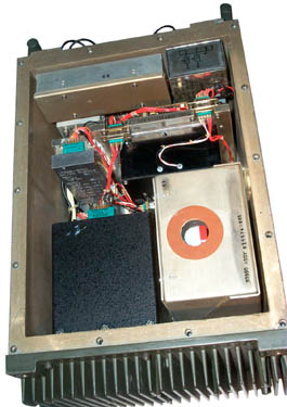 The black box
in front of the battery box is an 85 Watt DC to DC power supply,
input 16 - 32 V, output ? It has a hole that may be an output
voltage adjustment.
The black box
in front of the battery box is an 85 Watt DC to DC power supply,
input 16 - 32 V, output ? It has a hole that may be an output
voltage adjustment.
In front of the M100 is another DC to DC power supply, input +28
VDC, with outputs of: +28, +12, -12.3, +6.2 & + 6.3.
In front of the two DC-DC supplies is another PCB that has a
daughter board they have lots of through hole digital ICs.
There are four boxes on the back of the front panel, one is labeled
as a filter the larger box marked "69" in the front corner of the
photo is directly behind the three large connectors and is probably
also a filter.
The box below "69" has coax cables and is behind the BNC connectors
for 5 MHz In and Out and 10 MHz out. probably has the 10 MHz
splitter.
Guesses
The input is 16 to 32 VDC i.e. military vehicle "24 Volt" DC
power.
The 5 MHz input overrides the Rb source when connected,
otherwise the Rb is the master clock.
The Time Of Day signal has input and output pins on one or
more of the circular connectors on the front panel. Once TOD
is set this box has a clock that maintains TOD so it can be sent to
one or more radios when Send TOD is pressed.
The Rb frequency set screwdriver adjustment is behind an inspection
sticker.
Connectors
There are a number of Winchester
connectors. Positronic makes a
high
density
rectangular connector that's a 28748 type.
The SGMC20 might be the connector on the M100 Rb oscillator.
It has pin numbering:
A D H L P T W
B E J M R U
C F K N S V X
Operation
16 Oct 2007
The POWER connector is wired:
Pin
|
Function
|
A
|
Chassis
Gnd
|
B
|
+ 20 to
32 VDC
|
C
|
DC
return
|
The Battery contains 9 Cyclon Lead Acid 2 Volt 2.5 Ah "D" cells
for a total of 18 volts @ 2.5 Ah or 45 Watt hours.
The battery is made up of three strings of 3 cells.
Battery Connector is wired:
Pin
|
Wire Color
|
V @ Exp
Owr
|
Function
|
1
|
Black
|
gnd
|
gnd
|
3
|
White
|
0.9
|
+Vsense
|
5
|
Red
|
6.8
|
+Vbat
|
The cells were made in 1983, about 24 years ago and are now dead
beyond recovery. This is probably why these units are on the
surplus market. Although it's relatively easy to rebuild the
battery pack.
If +Vsense is connected to +Vbat then BAT STATUS lights when the
button is pressed. But if the battery pack is removed then
pressing BAT TEST does not light BAT STATUS.
Power Up
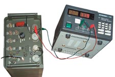
The HP E3617A bench
supply can only put out 1 Amp which is not enough to start this Rb
source. Using the B&K Precision 1786 that's good for 3
Amps worked fine. It came up at 27.7 Volts so that's what
I'm using. Just after power up the following LEDs are on:
Set CLock = Red
Cold Osc = Red
External Power = Green.
starting current about 2.2 Amps.
In 5 minutes the Cold Osc LED turned off. (I think this the fast
warmup option on the M100)
At any time pressing the Battery Test button causes it's green LED
to turn on.
Feeding the 10 MHz out to the SR 620 counter in frequency mode
gives the same display to 10 digits as the FTS4060 Cesium
standard. The SR 620 is using a GPS disiplined SR PRS10 Rb
standard for it's time base.
28 Oct 2007 after replacing the battery pack the supply current
after the oven has stabilzed is just under 1.2 Amps. So if
the main vehicle power failed after the O-1814 was warmed up it
should keep running for over 2 hours. Charlie's comment
above about "15 minutes" indidcates that the backup batteries have
been damaged.
Still need to figure out the connector wiring for Time Of Day
input and output.
Theory of Operation
From the POWER connector 16 to 32
VDC goes through a filter, the RESET breaker A5P1/A5J1 to the A2
Power Supply PCB that's below the battery and Rb standard.
From A2 to PS1 which is a DC to DC converter that outputs 28.0
Volt which is filtered by A5L1, A5D1 and A5C1 then goes to PS2
which provides the working voltages:
+28, +12, -12.3, +6.2 and +6.3 VDC.
The M100 outputs 10 Mhz to E2 of the active splitter that's behind
the 10 MHz Out BNC connector. E3 is probably 10 MHz that goes to
the A2 PCB which divides it by 2 generating a 5 MHz local
reference which is compared to the 5 Mhz input. If the 5 MHz
input is present that's fed to the Time Of Day PCB, and if not
present the local 5 MHz is used for TOD.
Outputs
The outputs are:
Time Of Day
5 MHz
There are a number of 800 kHz signals and it's not clear if these
have anything to do with the RFO or if they are just passed
between the UHF-AM radio and the SDU.
Time Of Day
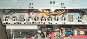
The A5A2 Time Of Day circuitry consists of two PCBs a mother board
that has two connectors and a daughter board with no connectors to
the rest of the O-1814. There's only one filter box behind
R/T-TS, SDU and RT-1319 and there are only 5 terminals and E1
(ground). They are: E2, E3, E4, FL2 and FL1.
Which may include: DC power, TOD data in, TOD data out, TOD clock
in, TOD clock out, and some type of data valid indicator.
Time Of Day is in a standardized military format that's supported
by many military GPS receivers like the
PLGR
and
Trimpack units. The
frequency hopping radios, like the RT-1319 (Have QUICK),
SINCGARS (RT-1439,
RT-1523) and others need Time Of Day to synchronize.
The KY-57 voice crypto does not need TOD, not does the internal
crypto in the newer SINCGARS radios.
There's a good chance that in addition to the clock and data lines
there is also a 1 Pulse per second output.
The Rx TOD and Tx TOD buttons are wired to the A5A2 TOD
board. The Set Clock LED has one side wired to the TOD board
and the other to the A2 board which controls the brightness of all
the LEDs by means of the Bright, Dim, Off switch. The Rb
interface is to the A2 board and it controls the Cold Oscillator,
Fault, Ext Pwr, Bat Status, Bat Test front panel items.

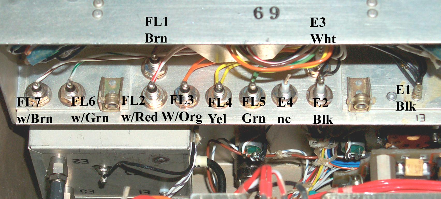
|
Back of
front panel.
Mirror view has been flipped so it
reads correctly. Showing the
Terminals on the side opposite
the main lid that's been removed
to get access to the inside.
|

|
RT-1319
-
SDU - R/T-TS
The RT-1319 is wired almost 1:1 with
the R/T-TS. The exceptions are pins:
4, 9, 10, 16, 17, 21, 25, 28, 29, 31, 32.
RT-1319 & R/T-TS pins: 11, 26 & 27 are ground.
|
|
|
A1-A1 Box behind RT-1319, R/T-TS & SDU
Feed
thru
|
wire
clr
|
VDC
|
4k7
Pull
Up |
4k7
Pull
Dn |
Description
|
RT-1319
Pin
|
R/T-TS
Pin
|
SDU
Pin
|
1 Jan
2009
TO 31R2-2GRC206-2-1
|
E1
|
Blk
|
0.000
|
na |
na |
chassis
ground
|
11, 26,
27
|
E
|
26, 27
|
|
E2
|
Blk
|
0.000
|
na
|
na |
chassis
ground |
11, 26,
27 |
E
|
26, 27
|
800 kHz
Return
|
E3
|
Wht
|
3.121
|
|
2.7
|
1 MHz
TTL out (modulation?) |
31
|
D
|
nc
|
800 kHz
Out
|
E4
|
Blu
|
5.39
|
|
4.3
|
? nc
inside box
|
nc
|
nc
|
nc
|
|
FL1
|
Brn
|
+8.6
|
|
5.0
|
?
|
nc
|
J
|
nc
|
TOD
Continuous
|
FL2
|
Wht/Red
|
2.4
0.3?3
|
5
|
0.0
|
Input (TOD?)
|
25
|
F
|
nc
|
TOD Out
|
FL3
|
Org
|
0.03
|
|
0.03
|
send TOD
4
|
10 1
|
B
|
nc
|
TOD In
|
FL4
|
Yel
|
5.67
|
|
5.63
|
?
|
21
|
A
|
nc
|
+5
Out
|
FL5
|
Grn
|
5.39
|
|
4.42
|
?
|
32
|
H
|
nc
|
External
800 kHz Enabl
|
FL6
|
Wht/Grn
|
2.4
0.03?3
|
|
0.03
|
10 us
pulse @ 32Hz (31.25 ms P)
|
nc
|
K
|
nc
|
|
FL7
|
Wht/Brn
|
0
|
0.2 |
0
|
?
|
nc
|
C
|
nc
|
nc
|
Note 1 - The
PLGR Have Quick TOD cable
uses pins 10 and 11 to load the TOD into the RT-1319/PRC-113.
Note 2 - It looks like the Signal Distribution Unit (SDU)
connector has no signals to or from the O-1814. The
RT-1319/PRC-113 does need TOD data and there are 5 lines going to
it. The R/T-TS has ALL the signals. This box
sits beteen the RT-1319/PRC-113 and the Signal Distrubution Unit.
Note 3 - These values are different than what was measured before
the standby battery was replaced.
Note 4 - This is the TOD message, but is all ones. i.e. a
positive TTL pulse 300 us long followed by a 300 us 0 volts.
Oct 31 2007 -the signal on E3 has two different pulse hi and pulse
low times so looks like some kind of modulation. This is
always on, not dependent on any button presses. The
frequency is between 714 kHz and 1.5 MHz. Capturing some
pulses in single shot mode shows :
Time Hi us
|
0.8
|
|
0.6
|
|
0.88
|
|
0.78
|
Time Lo us
|
|
0.6
|
|
0.5
|
|
0.4
|
|
After doing the Pull Down measurements the voltages on FL2
and FL6 are considerable different than they were when first
measured. This may be related to having a working backup
battery now and they a dead backup battery? The HP 54501
scope shows a Have Quick data pattern of FL3 that lasts about 277
ms when the SEND TOD button is pressed. It's a square wave,
i.e. there's is no TOD in the O-1814 so it's sending a null
string. But at least the function of one line is now
known.
The pulse on FL6 is the same as before a 9 us wide pulse with a
rep rate of 32 Hz. Don't know what that's about.
FL1 is interesting in that it's open circuit voltage is +8.6
(above TTL) and it comes down to 5.0 V when a 4k7 resistor is
pulling it toward ground.
The RT-1319/PRC-113 has the ability to output it's TOD so it can
load the O-1814 with the TOD. Military GPS receivers have
two functions, the most commonly known are the functions relating
to position, but the other is to load TOD into equipment that
needs it.
Have Quick
Have Quick is the name associated with frequency hopping
radios. It's usually applied to the UHF air band radios like
the PRC-113 or VRC-83 that use the RT-1319 or to the aircraft
radios. The details are not in the public domain and so need
to be figured out. It seems that HQ equipment can both
receive and send the TOD. There are different flavors of
Time Of Day (TOD). But all of them have the same
starting data so an older radio that's expecting the basic message
will correctly load the front part of an extended message and
ignore the remaining bits. This is know as backward
compatible.
The
SINCGARS time (TM 11-5820-890-3)
is different from the Have Quick time. In SINCGARS the date
is just 2 digits which are the last two digits of the annual
Julian day number. There are two calendars, one for regular
years and one for leap years. For both Feb 28 is day
59. For a regular year April 10 is day 00 as is July 19 and
October 27. In a leap year the 00 dates are April 9, July 18
and October 26. The SINCGARS radios resynchronize their TOD
for the current channel every time the Net Control Station
transmits. The Have Quick radios do not do this. The
crystal oscillator in the Have Quick radios is only good for about
4 hours then has drifted to where they no longer will work.
Have Quick radios can get an off the air TOD but it's a manual
procedure.
The
Wiki Have
Quick page says the Radio needs:
- accurate Time Of Day (TOD)
- Word Of the Day (WOD)
- NET number
All of the above three elements are needed for the frequency
hopping.
Basic Have Quick TOD Message (STANAG 4246 HQ1)
Sends the Hour, Minute and
Second. Message is less than 1 second long and uses BCD
coding. Very much like the
WWV
and
WWVB time codes that take
one minute to send. Maybe if it's 3:46:27 pm (15:46:27
UTC) the BCD values sent would be 1, 5, 4, 6, 2, 7 and each
digit would take 4 data bits for a total of 24 bits. But
if self clocking Modulation is used then you can think of that
as using 2 message bits for each data bit and so the number of
message bits is doubled to 48. For example a 1 data bit is
a message of "10" and a zero data bit is a message of
"01". This scheme is self clocking so a seperate clock
wire is not needed. That's consistent with the
PLGR to Have Quick cable having
only signal and ground wires. The
crypto fill system uses seperate
clock and data lines.
Have Quick II (STANAG 4372)
The basic HQ message then Day of
the Year as 3 BCD digits (3 * 4 * 2 = 24 bits) and two digit
Year (2 * 4 * 2 = 16 bits)
GPS Based Have Quick (ICD-GPS-060) aka PTTI HQ
The HQII message then Time Figure
Of Merit. The TFOM covers the range of 1 ns to 10
ms. On the PLGR GPS receiver it's expressed as a single
digit from 1 (<= 1 ns) to 9 (>= 10 ms). So 1 digit *
4 bits/BCD digit * 2 bits message coding = 8 bits.
The ICD-GPS-060 spec has two protocols.
One is a two wire differential (maybe like RS-422 or RS-485
haven't checked that) and the other is a single ended TTL
level Extended Have Quick.
There's also a timing fault wire that has a TTL level for OK/NG.
| Description |
1PPS |
Data |
duration
ms |
End
since 1PPS
ms |
| Data Frame |
10V
20 us |
400
"1" char |
240 |
240 |
| " |
0V |
16 bit Sync word |
9.6 |
249.6 |
| " |
0V |
2 digit hour |
9.6 |
259.2 |
| " |
0V |
2 digit minute |
9.6 |
268.8 |
| " |
0V |
2 digit second |
9.6 |
278.4 |
| " |
0V |
3 digit DOY |
14.4 |
292.8 |
| " |
0V |
2 digit Year |
9.6 |
302.4 |
| " |
0V |
1 digit TFOM |
4.8 |
307.2 |
| " |
0V |
low |
692.8 |
1000 |
| |
|
|
|
|
| 16 bit Sync word |
|
11E9 hex |
|
|
| |
|
|
|
|
| "1" char |
|
300 us hi |
|
|
| |
|
300 us lo |
|
|
| |
|
|
|
|
| digits |
|
1667
bits per sec
600 us per bit |
|
|
| digits |
|
4
parity bits
then
4 data bits |
|
|
The parity bits come from a table that's based on the idea of
not only detecting an error but of correcting as many bits of
error as possible.
Extended Have Quick (STANAG 4430)
The GPS HQ message then bits for a
more accurate TFOM, Continuation data, Leap Seconds and an End
Of Message terminator. Maybe if there is no message
terminator the message can be repeated with the continuation
data different in each sussive data packet?
HQ Physical Layer
Depending on the flavor of HQ it may be as simple as a ground and
a data wire. The O-1814 has two front panel buttons RCV TOD
and SEND TOD. The SEND TOD might be the simple method.
The RCV TOD could also just enable one frame of reception of a
data stream but it's more likley that there's a more complex
physical layer like a seperate wire for a "load me" request and
maybe a seperate clock wire.
Backup Battery
The battery is a backup for the main
DC input and will keep the Rb alive and the TOD will be maintained
as long as the internal battery lasts. When the front
panel RESET/OFF switch under the red cover is turned off the
internal batteries do NOT power the unit and it forgets
everything. When the switch is on and there is external
power the battery is float charged. If the external power
fails with the switch on the batteries are used to power the
O-1814. They are rated at 2.5 AH and the unit draws about
half of that so they should last at least a couple of hours.
These Cyclon circular "D" cell size lead acid batteries were
developed for standby applications very similar to this where they
power the equipment when the power fails and are recharged
immediately after the power comes back on line. They will
survive being drained to zero capacity in this application IF THEY
ARE RECHARGED A SHORT TIME LATER. This is far different from
other batteries which will be ruined if discharged to zero.
But if the Cyclon is discharged to zero and left discharged for
some time it takes a special procedure to attempt recovering their
capacity.
If a user of the
GRC-206 system shut it down from the Power Distribution Unit,
i.e. turned off all the radios and the O-1814 from the PDU and
walked away the backup battery would power the unit until it was
flat. Turning off the GRC-206 system at the Power
Distribution Unit does not turn off the RFO. But it would
not get recharged until the next mission thus degrading the
capacity after the next charge. But if as part of the power
down sequence the O-1814 was turned off first then the batteries
would drain at their shelf life rate. They could sit for
many years if starting out with a full charge. 2009 - It's
still a mystry about the poor performance of the RFO.
Jan 2009 - The manuals mention that as part of the receiving
inspection the internal On-Off switch should be turned on.
This switch is located in the backup battery circuit. It
must be on for the backup batteries to work.
Description
The OFF/RESET switch is a DPDT type that completly disconnects the
external power from the O-1814. But it also has a ground
connection on the input side that gets opened when the switch is
opened. This gives a signal to the A2 PCB that turns off the
internal backup battery (it may be as simple as the backup battery
ground connection is through this wire).
There's a sticker on the right side that says:
WARNING
REMOVE
BATTERIES BEFORE
SHIPPING
OR INACTIVE STORAGE
OF 30
DAYS OR MORE
It seems that someone didn't follow that advice. But the
batteries have not yet started to leak.

The battery
box is lined with the same Rodgers Poron Urethane Foam that's used
for skin diving suits. Although there is a vent hole that's
aligned with a plug in the bottom cover it appears to be a safety
vent. Thre's no provision to keep acid fumes from getting to
the electronics, but it may be that the Cyclon cells are well
sealed.
There are more patents on the
Cylindrical
Lead
Acid cell than are shown on my Battery Patents web page.
26 Oct 2007 - received replacement backup batteries. The
dead battery packs were marked 810-0113CC for each 3 cell pack,
but the new ones are the 0810-0103 and appear to be the an exact
replacement. Note these are the cylindrical cell CYCLONs the
dead ones were made by Gates and the new ones are branded EnerSys.
As received the 3 cell packs were at 6.15 Volts Open Circuit
(VOC). The applications manual says that's about 60%
capacity. 1.95 V/cell is 10% and 2.14 V/cell is 100%.
The recommended float charge is 2.30/2.25 Volts/cell or 20.7/20.25
Volts per pack of 9 cells. With a bench P.S. set to 20.5
volts the 9 cell pack is drawing about half an amp in Constant
Voltage mode. After 45 minutes the float current is down to
318 ma. The next morning is was down to about 20 ma. After
powering from the external supply and waiting for the Cold
Oscillator light to go out the external supply was
disconnected. The Ext Power lamp stayed green for an hour
and the battery terminal voltage was 16 Volts or below the zero
capacity value so the test was stopped and external power
restored. This should charge the battery.
29 Oct 2007 - after more than 24 hours of charging the battery
voltage is 19.9 measured with the main power switch off so there
is no float charging. The battery pack voltage varies from
17.55 at zero capacity to 19.26 for 100 % capacity, so 19.9 Volts
is a little more than 100 %. It may be that a small load or
some amount of time needs to pass after taking the batttery off
float charge is needed to get an accurate reading of
capacity. In any case the float charger has filled up the
battery.
M100 Rubidium Standard
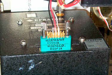
The Three wires are:
Black = ground, red = +22.5 to +32 DC power and wht/vio = lock
indication out.
The coax coming from J1 is the 10 MHz out.
The frequency adjust pot is behind the "EFRATUM, Inspected by:, 1,
8311.16" label in the lower right corner. The label just the
the left says "Freq Adj".
The back (bottom of this view) of the M100 is thermally connected
to the rear heat sink fins.
The 20 contact (SGMC20) multipin connector only has:
J2-L: Red +22.5 to 32 VDC in
J2-P: Black Ground
J2-F: Crystal control voltage signal = n.c.
J2-H: white/violet - Reasonance Lock Signal
J2-B: Rb lamp voltage signal = n.c.
J1: 10 MHz Out
All other pins not used.
A D H L P T
W
X
V S N K F C
B E J M R U
-ROTATED-> U R M J E B
C F K N S V
X
W
T P L H D A
J2-H and J2-L and J2-P match the photo for the rotated version.
There are a number of these M28748
type
connectors in the O-1814. They may
be called Winchester connectors.
2659872
Electrical Connector Hood Assembly, Jun 10, 1950, Winchester
Electronics Inc., 439/248 ; 439/680; 439/901; D13/147
Disassembly
With the bottom cover off the
connectors on the battery and M100 can be removed.
The battery can be removed.
The rear cover can be removed and the M100 at attached to the rear
cover.
It looks like a number of connectors and cables need to be removed
so that the aluminum plate holding the power supplies and digital
PCBs can be removed.
Removing the PCB that's under the M100 and battery looks to be
straight forward after the rear cover is removed.
Manuals
T.O. 31R2-2GRC206-1-1 Supplemental
Operators Manual AN/GRC-206(V)3
T.O. 31R2-2GRC206-2-1 Supplemental Maintenance Instructions
AN/GRC-206(V)3
both of these are mainly concerned with the O-1814 and are
probably all the documents about it.
Modification Ideas
GPS Disciplined Oscillator
The M100 Rubidium oscillator Electrical Fine Tuning could easily
be wired to a front panel connector pin that would allow
controlling the frequency using one of the GPSDO controllers that
are now available.
Links
back to Brooke's: PRC68, Products for Sale, Time & Frequency, Military Information, personal
home page
[an error occurred while processing this directive] page created 15
Oct 2007, updated Jan 2009


 RT-1319: MS27468-P15B-35S connector (the
RT-1319 is the Have Quick UHF radio)
RT-1319: MS27468-P15B-35S connector (the
RT-1319 is the Have Quick UHF radio)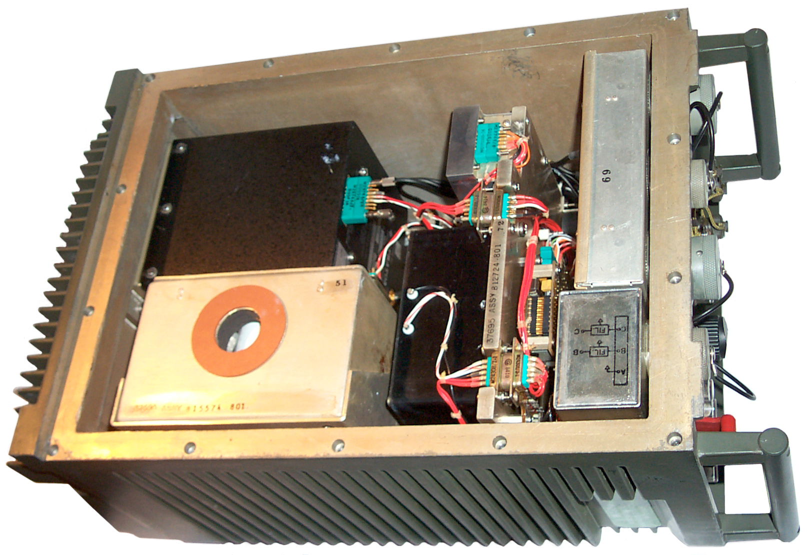 The lower left box with
the orange circle is the battery box. It's held in by 6 thumb
screws that have slots for a long blade screwdriver. The 9 pin
D-sub connector only has Red, Black and white wires connected.
The lower left box with
the orange circle is the battery box. It's held in by 6 thumb
screws that have slots for a long blade screwdriver. The 9 pin
D-sub connector only has Red, Black and white wires connected. The black box
in front of the battery box is an 85 Watt DC to DC power supply,
input 16 - 32 V, output ? It has a hole that may be an output
voltage adjustment.
The black box
in front of the battery box is an 85 Watt DC to DC power supply,
input 16 - 32 V, output ? It has a hole that may be an output
voltage adjustment.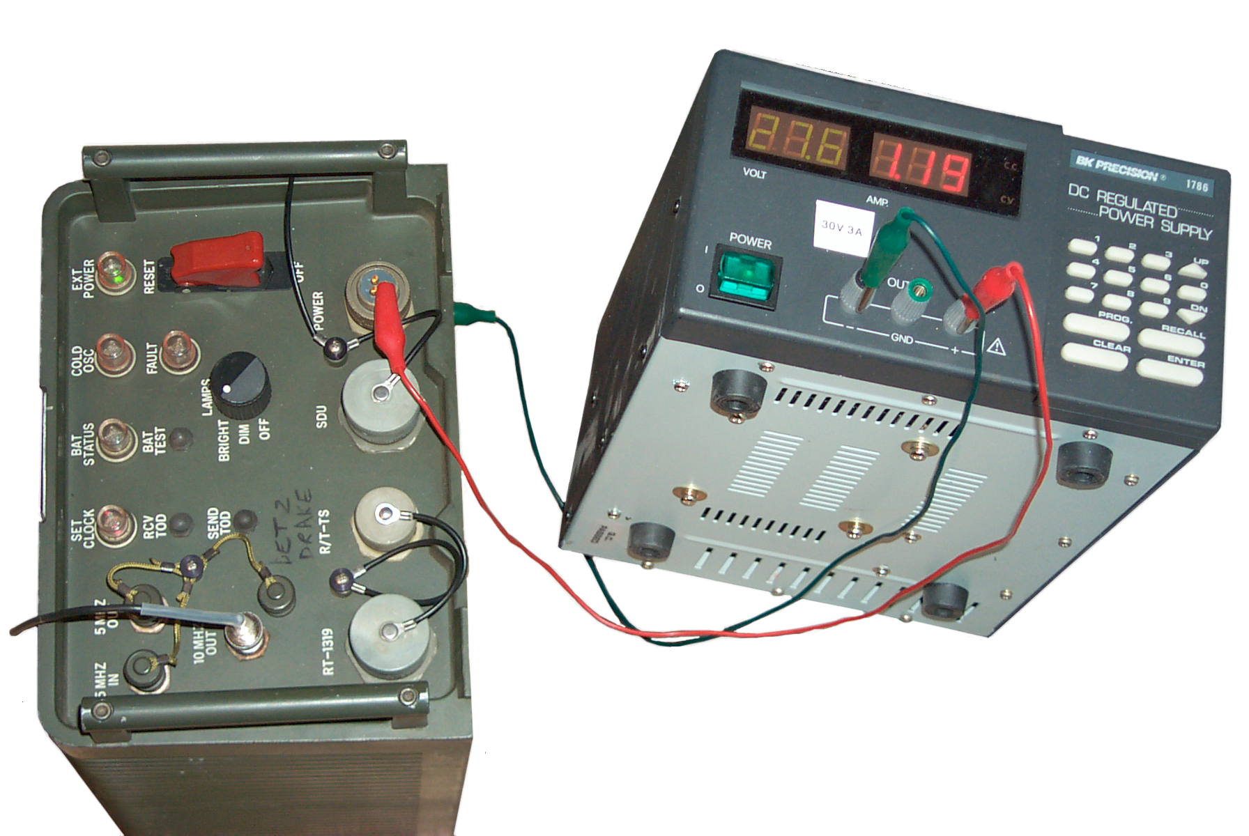 The HP E3617A bench
supply can only put out 1 Amp which is not enough to start this Rb
source. Using the B&K Precision 1786 that's good for 3
Amps worked fine. It came up at 27.7 Volts so that's what
I'm using. Just after power up the following LEDs are on:
The HP E3617A bench
supply can only put out 1 Amp which is not enough to start this Rb
source. Using the B&K Precision 1786 that's good for 3
Amps worked fine. It came up at 27.7 Volts so that's what
I'm using. Just after power up the following LEDs are on: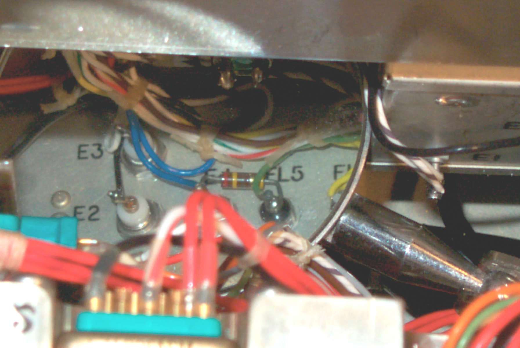
 The battery
box is lined with the same Rodgers Poron Urethane Foam that's used
for skin diving suits. Although there is a vent hole that's
aligned with a plug in the bottom cover it appears to be a safety
vent. Thre's no provision to keep acid fumes from getting to
the electronics, but it may be that the Cyclon cells are well
sealed.
The battery
box is lined with the same Rodgers Poron Urethane Foam that's used
for skin diving suits. Although there is a vent hole that's
aligned with a plug in the bottom cover it appears to be a safety
vent. Thre's no provision to keep acid fumes from getting to
the electronics, but it may be that the Cyclon cells are well
sealed.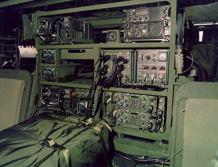