Trimble ThunderBolt Timing GPS Receiver GPSDO
© Brooke Clarke 2008
| mAmps |
+5 |
+12 |
-12 |
| Cold |
224 |
678 |
2 |
| Warm |
246 |
144 |
2 |
 All the wires need to be removed and replaced with an AC line cord and a cable & connector to mate with the Thunderbolt. |
 |
 |
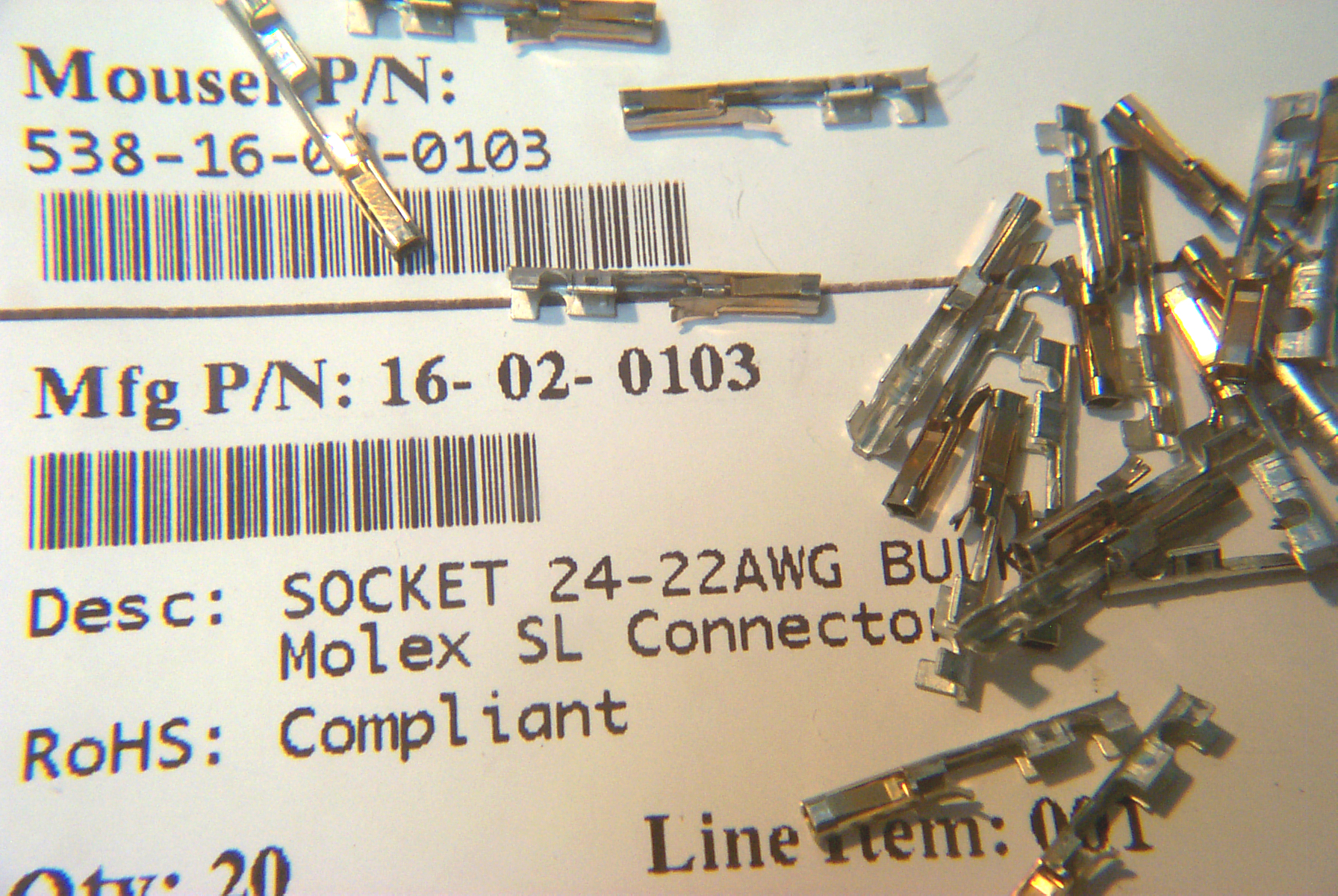
| Molex
16-02-0103 female contact pins |
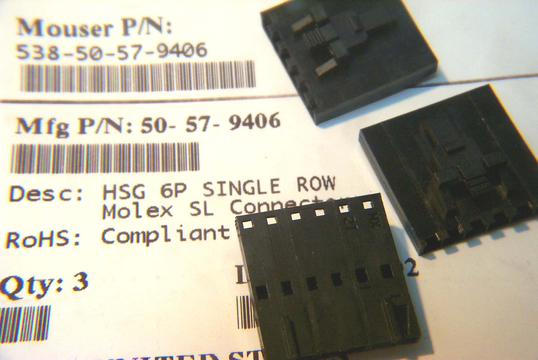
Molex
50-57-9406 6 position shell |
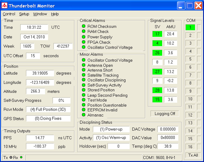
 This
is a Windows program that allows setting up and monitoring the
operation of the ThunderBolt receiver. The program is not
required and can be disconnected from the receiver once you are
happy with it's settings.
This
is a Windows program that allows setting up and monitoring the
operation of the ThunderBolt receiver. The program is not
required and can be disconnected from the receiver once you are
happy with it's settings.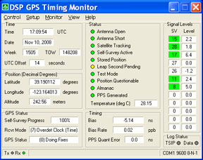 This is the program that's used with the Thunderbolt
E (although the manual for the E version has information about
another program). Once you right click and set the serial port
to COM 1 9600 8-N-1 it works with the non E version. The
Timing area has three data fields compared to the Timing Outputs
area of the Thunderbolt Monitor program the new field is called PPS
Quant error 0.0 ns. When run with a non E version Thunderbolt
this field is always 0.0.
This is the program that's used with the Thunderbolt
E (although the manual for the E version has information about
another program). Once you right click and set the serial port
to COM 1 9600 8-N-1 it works with the non E version. The
Timing area has three data fields compared to the Timing Outputs
area of the Thunderbolt Monitor program the new field is called PPS
Quant error 0.0 ns. When run with a non E version Thunderbolt
this field is always 0.0. |
Prior to doing the screen
dump I pressed t (time and temperature control), Z (time zone) and GMST (Greenwich Mean sidereal time), but something is wrong since the time display is not incrementing every second, more like once every 25 seconds! |
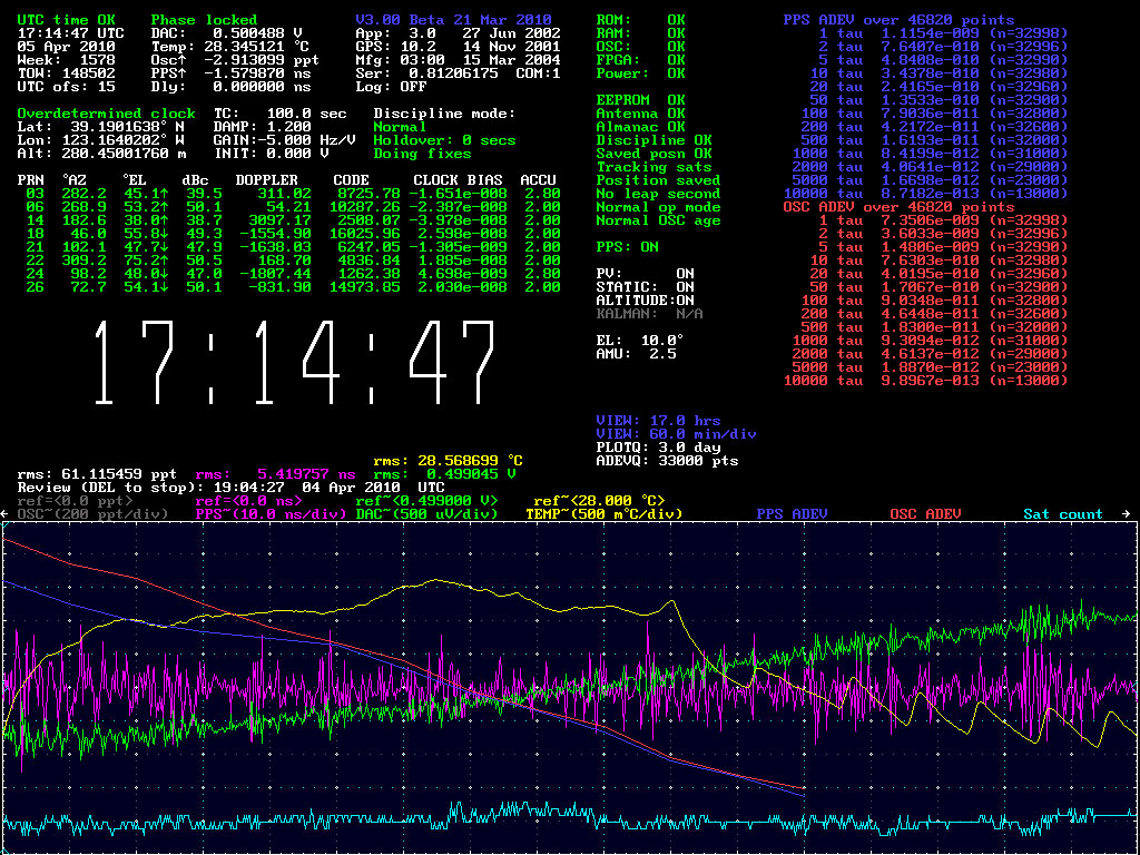 |
To get this screen dump from
a full screen image I pressed <CTRL><Print
Screen> then F11 to go back to a LH window. But
that caused 3.0 beta to crash and bring up the report an
error window WIN XP SP2. Click on the image (17:14:47) to see the full size version. |
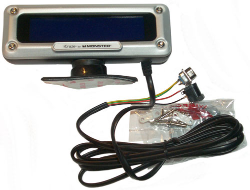 |
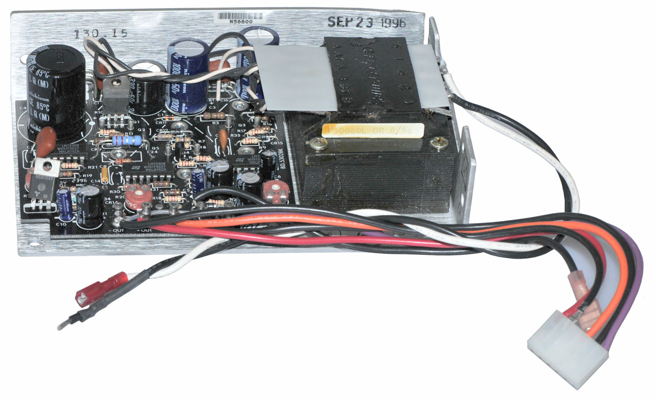
Available from fluke.l Power Supply Voltage: 5.0 Red=+ It turns out that this is one of the newer (Dec 2009 and later) units that has an on board 78D05 regulator on the samll PCB near where the 4 wires are soldered to the board. These units need at least 7 VDC to work and will work fine from +12 VDC. |
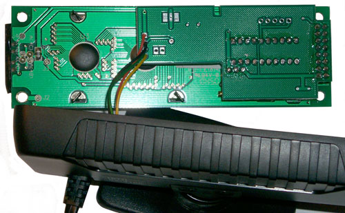 |
A T10 Torx bit is needed to
open the case. The lower PCB is the 2x20 LCD and the
daughter board is the custom uC for the Thunderbolt. To the right and above where the wires are soldered you can see a group of 3 pads, two rectangular with a trace between them. The 78D05 is there on the other side of the board. |
 Since the display is on a cable it can be located where it can be seen not where the Thunderbolt is located. This makes the display much more useful. Something has happened, the display is now blank? It is dead! I think either static or applying 6 VDC to the input (adjustable lab supply) since there's no input regulator. Working fine on on +12 V input. When I turned the supply down from 6 to 5 V that caused the 78D05 to drop out, turning it off. |
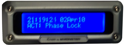
The top line displays either
GPS or UTC time & Date depending on how the receiver is
set. The second line shows: No Message if it's not connected to the serial port of the Thunderbolt, or alternating: MODE: Normal ACT: Phase Lock RX: Overdet Clk GPS: Doing Fixes TEMP: 32.45 DAC V: 0.4874 |
iCruze Apr 2010 Broken Again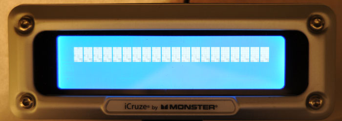 April 2010 - the iCruze Thunderbolt monitor no longer displays No Message or anything else. This is the display and is no related to the RS-232 input. Don't understand why. |
The problem may be static zap
to the RS-232 connector since I was using it without the
cover installed. |
Tunderbolt
GPS
iCruze Monitor 8051 PCB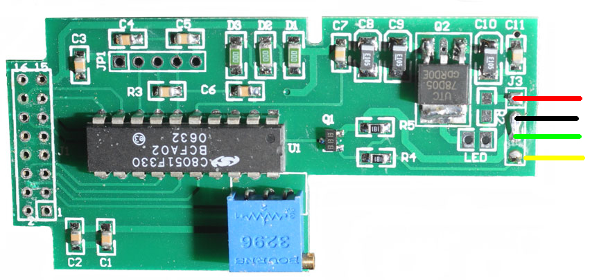 |
The Voltage regulator (Q2) is
a 78D05 and D1, D2 & D3 are 000 Ohm resistors which
means the C8051F330 uC may be powered by a voltage that
exceeds it's specs. |
| 21 Nov 2014 - Comment from "If you refer to the picture of the microprocessor board, you will notice that the locations marked D1, D2 and D3 are populated by zero ohm resistors. That means that the 3 V microcontroller was powered from 5V. I am actually amazed that they worked at all, let alone worked for a while. It is a shame that fluke.l saved on the cost of 3 diodes that way. The 1N4148 is $.02 at Mouser in 25 pieces lots. - Didier KO4BB What I did (and I've mentioned this before) is to replace the three zero ohm resistors with one red LED. The forward voltage drop is about 1.7vdc so it makes a pretty nice zener, and you have a power indicator to boot. -Arthur |
|
Tunderbolt GPS iCruze Monitor
Replacement CPU Board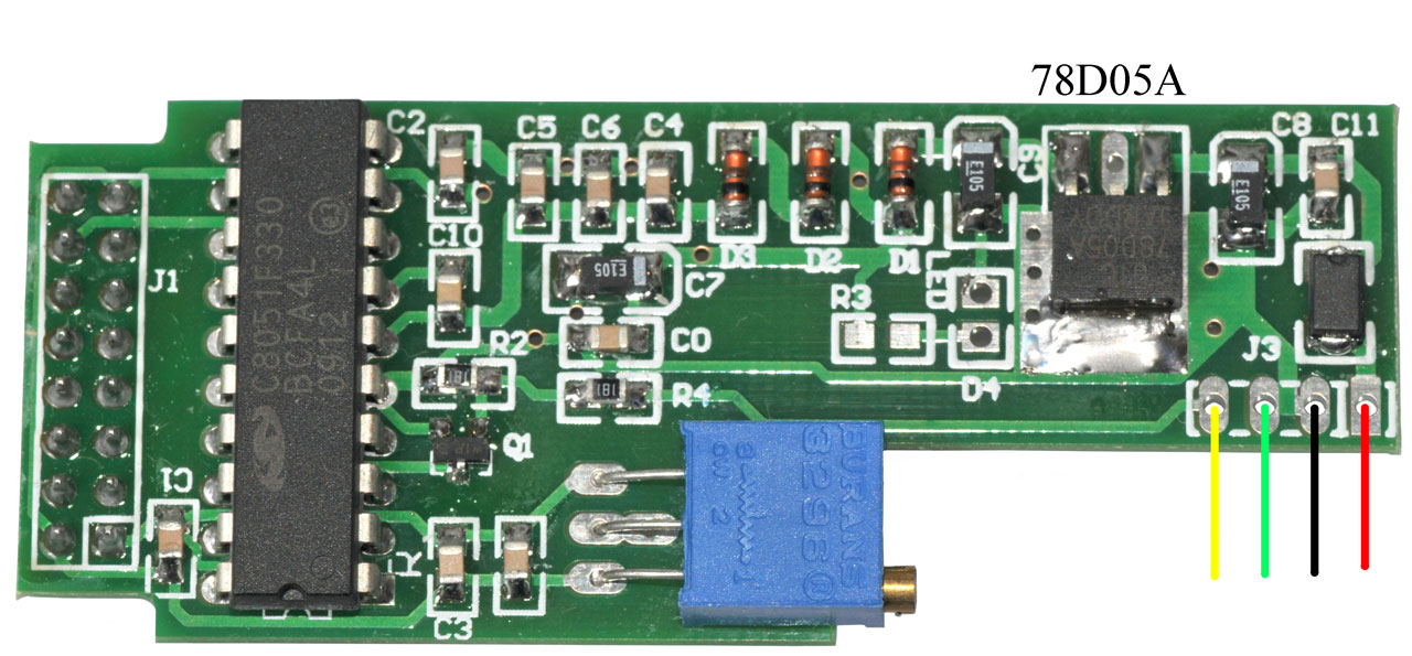 |
This is the newest CPU board. Wouldn't you know that I removed the header pins from the wrong PCB. The wire colors are my best guess. |
| ID | Mfg | Function | Marking | Date |
| F2 | GI | GPS BP Filter | GI M37 | |
| U01 | CY | 128x8 RAM | 62128BLL-70SC | 0402 |
| U02 | Trmbl | GPS uC |
F.W.=3.00 48051-30 | |
| U05 | ON | Logic | 74HCU04A | |
| U06 | CSI | Logic | 93C865 | 0341C |
| U07 | generic | 512kx8 Flash Memory |
29F400BB-120EI | |
| U09 | DS | Thermometer | DS1620 "0310D1" = rev D ( good) the "E" rev has poorer resolution |
|
| U10 | MACOM | 27 dB Low Noise Amp | AM50-002 | |
| U14 | TI | Logic | 74AC174M | 35AYC8M |
| U15 | LT |
V. Ref |
LT1021-5 | |
| U17 | Linear | Quad Op Amp |
LT1014 ISW N08316 | 0401 |
| U18 | I | RS-232? | 232IBE | 41Z1L |
| U19 | TI | Logic | 74AC04M | 3CC7EVK |
| U20 | TI | Buffer Amp |
OPA692 | |
| U22 | Xilinx | 256 cell FPGA | XC5202 | |
| U411 | Infineon | GPS RF Tuner |
PMB3332 | 0342 |
| U460 | TI | 7301Q 3CT | ||
| U461 | ST | Logic | 74VHCT32 | |
| U999 | Sawtek | Filter | 855242 | 009410 |
| Y1 | 32.768k | RTC xtal |
||
| Y2 | 3.6864 | CPU xtal |
 |
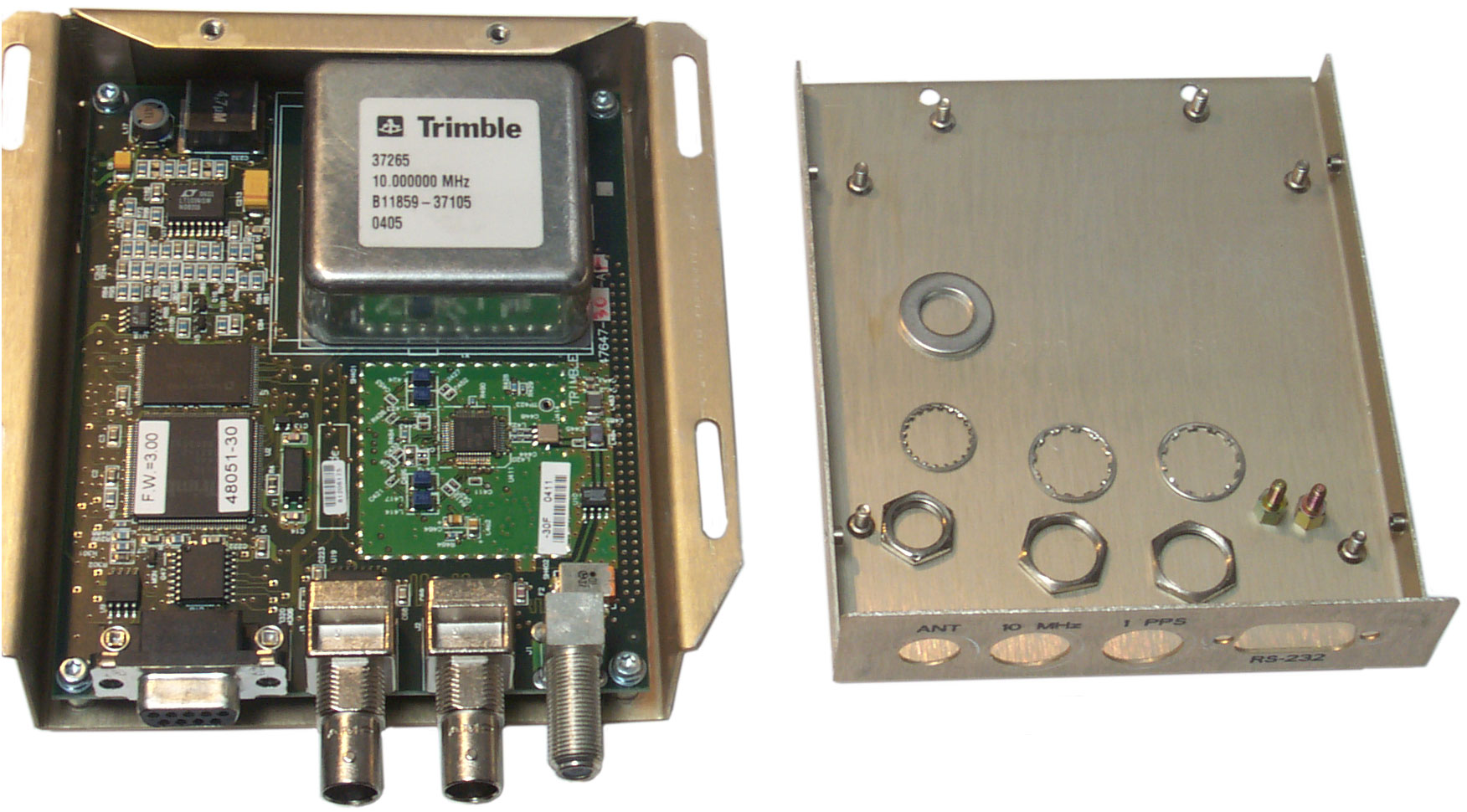
When you look at the bottom of the PCB (left side in photo at left) in the space under the OCXO there are two hole patterns like for a SMA, SMB, SMC or similar solder in coax connector. That would be consistent with a 10 MHz signal to the PCB and a tuning voltage signal to the external oscillator. Note that one of the TSIP commands allows configuring the tuning voltage parameters and is also part of the Tboltmon program. |
Option No.
Resistor
value
Function
1
R320
?
brings 10us wide PPS out to pin 6 (DSR)
| Pin |
Function |
Voltage |
| 2 |
Data Out |
-11.3V
jumps
once/second |
| 3 |
Data In |
0 |
| 5 |
Ground |
0 |
[an error occurred while processing this directive] page created 6 Nov 2008.