Seismometer
© Brooke Clarke 2007 -2020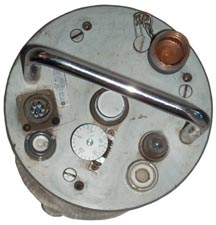 |
 |
 |
|
| Hilger & Watts Seismometer |
Geophone | Quake Alarm | EarthQuake Alert |
Vibration Sensors
Hilger & Watts
Kinemetrics
SH-1 Horizontal Seismometer
Cal Tech (SH-1)
FC-1 Field Calibrator
SMA-1 Seismograph
Geophone
Quake Alarm
EarthQuake Alert
Atomic Bomb Test Ban
Earthquake Early Warning
Quake-Catcher Network
Earthquakes
Patents
Related
Links
Background
British Geological Survey: History of seismometer design -
YouTube:
USGS:
Earthquakes
Classically seismometers have been used to record the ground shaking as the result of earthquakes. By measuring the time from the "P" wave to the slower waves the radial distance between the sensor and epicenter can be calculated. The magnitude and duration of the slow waves gives an indication of the energy. This is the application that first got me interested.Oil Exploration
Geophones are used to look for reflections caused by changes in density of sub surface layers after a surface explosion or a tamper initially shakes the ground. These are typically used in large arrays.Intrusion Detection
Outdoor intrusion detectors use geophones as well as other methods to detect ground vibrations caused by moving men and machines. Knowing about the use of seismometers for recording earthquakes and then seeing this application reinforced my interest.Machine Balancing & monitoring
Some industrial motors are connected to a system that can be
balanced so sensing the out of balance helps make the initial
adjustments. In an industrial environment when a machine is breaking down or is about to, it starts to shake and detecting the vibration allows shutting the motor off before there's a catastrophic problem.
Detecting Nuclear Blasts
As part of the Non Nuclear Proliferation treaty a need arose to detect nuclear blasts and differentiate them from other types of blasts. Seismometers are able to do that by the wave form shape.Note that the technology used for seismometers is very similar to that used for pendulums and gravity meters.
Monitoring Blasting associated with Mining
The book Blasting Guidance Manual (Google
Books) lists the following companies that make seismic
recorders to monitor blasts for compliance with federal
rules:
Dallas Instruments, Digital Vibration Teleblast, Berger,
Slope Indicator, Sprengnether, Vibra-Tech (VME). I saw
a Berger SSU 1000D on eBay listed as "Geosonics Berger &
Associates Portable Seismograph Seismic Unit SSU
1000D" The sensor stored in the lid looks like a
microphone rather than a seismometer and it turns out that
it's used as a trigger for the chart recorder. The
black device may be the vibration transducer.
Vibration Sensors
Hilger & Watts
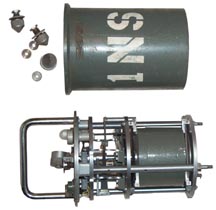
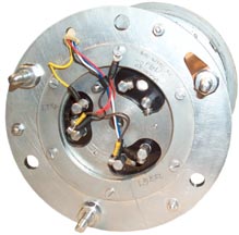
Label SG450, 157222, Made in England.The Teledyne Geotech S13 Seismometer looks very similar and they show up on eBay now and then.
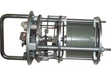
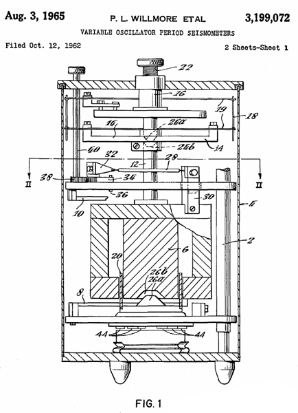
Variable Oscillation Period Seismometer (see patent below) that can be used vertically or horizontally. Permanent magnet and coil of wire.
 |
 |
 |
 |
| Hilger
Watts Seismometer Open |
Hilger
Watts Seismometer Close Up |
Bottom
showing
2 of 3 possible windings |
Top |
Mechanical
Spring Lifting System
The arms (14) are firmly attached to the magnet by a central rod. Four triangular leaf springs (19) their base ends clamped to arms (14) and their pointed ends are linked (18) to the pointed ends of the top springs (19). There's a plate anchored to the frame (shown just above 26a) which holds brackets at the base of two of the top springs (19). One of these is shown in the upper left of the drawing. There are two Allan head screws that clamp the spring to the bracket (the upper left screw and another behind it not shown). There are two pivot screws whose ends sit on the plate (above 26a) shown as the single screw to the right of the bracket. The central screw goes through a clearance hole in the bracket and into a tapped hole in the plate. These two screws have horizontal holes in the head so they can be adjusted from the side.Spring Lifting System - Not shown in patent drawing
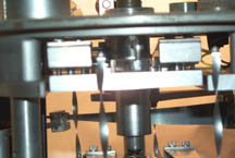 The
other two top springs (19) are held by an identical pair of
brackets, but instead of being connected to the plate (above
26a) they are connected to a plate that's been cut out of the
first plate. An an are bolted to the top of the plate
(above 26a) and cantilevered out over the cut out section of
plate. In it's outer end there's a tapped hole.
The screw in that hole can be turned to cause the floating
plate to move and this changes the tension of the spring
system. The screw can be accessed by removing the large
headed screw that holds the cover over the clamping screw
(22). The highest dial setting that I can get to work in
the vertical position is "18" and here the spring lifting
system adjustment screw is backed out so that it's
cantilevered is almost touching the floating plate.
The
other two top springs (19) are held by an identical pair of
brackets, but instead of being connected to the plate (above
26a) they are connected to a plate that's been cut out of the
first plate. An an are bolted to the top of the plate
(above 26a) and cantilevered out over the cut out section of
plate. In it's outer end there's a tapped hole.
The screw in that hole can be turned to cause the floating
plate to move and this changes the tension of the spring
system. The screw can be accessed by removing the large
headed screw that holds the cover over the clamping screw
(22). The highest dial setting that I can get to work in
the vertical position is "18" and here the spring lifting
system adjustment screw is backed out so that it's
cantilevered is almost touching the floating plate.Setting Period
If you have any documentation on how to use this Hilger & Watts seismometer please let me know.
Electrical
| Coil Position |
Wire Color |
Connector |
| A |
na |
na |
| B |
na |
na |
| C |
White |
B |
| D |
Blue |
broken |
| E |
Black |
A |
| F |
Yellow |
F |
| Chassis |
Red |
broken |
Period
The dial calibrated from 0 to 25 which should change the period instead seems to move the mass up or down and when at 15 the rod in the height viewing dome is level with the center fiducial mark. Moving this dial to either extreme bottoms the mass.The label on the outside "1NS" implies this was used in the horizontal position. But when placed horizontally the mass locks up. So it's really not working correctly. There is probably something that needs to be done to get proper operation when vertical, which is the position I'd like to use.
These look similar to the sensors used in the GR-8 Sound Ranging Set.
Patents by Willmore:
3897686 Spring suspension for measuring instruments, Patrick Lever Willmore, 1975-08-05,3199072 Variable Oscillation Period Seismometer, Patrick L. Willmore, Hilger & Watts, August 3, 1965, 367/185
2933715 Seismic Device, Beuermann (Firma Seismos, DE), Apr 19 1960, 367/184 ; 310/15; 310/27; 73/654 -
3297982
GB2055169 (eSpaceNet) Compression spring particularly for use in vertical seismometers, Willmore P L, 1981-02-25, -
GB980496 (eSpaceNet) (3199072) Improvements in or relating to seismometers, David Vivian Connell, Patrick Lever Willmore, Hilger and Watts Ltd, 1965-01-13, -
Kinemetrics (Wiki Support web page)
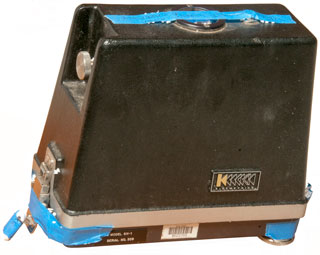
SH-1 Horizontal Seismometer
Fig 1
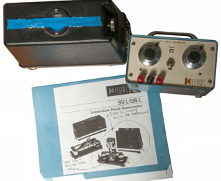
Fig 2 FC-1 Field Calibrator
Cal Tech
Interesting photo from eBay of a vertical pendulum unit that is the SH-1 & label shows patent 3685011.
3685011 Seismometer, Francis E. Lehner (Cal Tech), Aug 15 1972, 367/182 ; 73/654 - coil in magnet type with calibration pulse input, maybe 5 second period (adjustable).
Calls:
3194060 Seismic Displacement Transducer, L.T. Greenwood (NASA), Jul 13 1965, 73/654 ; 367/179; 73/382R -
2074043 Seismograph, Louis Statbam (Std Oil), Mar 16, 1937, 367/182 ; 310/15; 73/654 - cylindrical package, down hole? permanent horseshoe magnets
2873103 Seismological Instruments, R.F. Hautly, Feb 10 1959, 73/653 ; 73/514.14; 73/650 - torsional damped limited frequency response reflecting mirror
Calls:2842752 Geophones, W.M. Jones (British Petrolum), Jly 8 1958, 367/182 ; 267/160; 336/100; 336/136
1869828 Devices for Measuring and Recording Vibrations in Three Directions
2268526 galvanometer
2487793 Object Controlling Electric Motor System, (Sperry Gyro) - used as part of aircraft auto pilot
2542018 Compass, Ferrill (Sperry Corp), Jr. et al, Feb 10 1951, 33/360 ; 33/362; 33/363Q; 73/504.14 - vibratory compass
2552722 Electromagnetic Accelerometer, John G. King, May 15 1951, 73/514.12 ; 324/127; 33/DIG.5; 336/135; 336/30; 336/67; 336/92; 336/94; 340/870.35; 73/514.31- magnet if bob of pendulum
2616681 Angular Velocity Responsive Apparatus, C.T. Morrow (Sperry Corp), Nov 4 1952, - ref 2513340
2852769 Time Interval Multiplier, R.L. Plouffe (Navy), Sep 16 1958, 342/186 ; 327/134; 327/172; 327/174; 368/115
3704764 Air deliverable seismic system, Harold B Henderson, Texas Instruments Inc, Dec 5, 1972, - from patent number of a different seismometer on eBay.FC-1 Field Calibrator
All the connections are on the front panel.
It appears the input is modified by a "Sensor" factor and an "acceleration" factor and an output results.
See photo above with SH-1 and SH-1 documents.
SMA-1 Seismograph
Background
This is an early 3-axis seismograph (meaning it makes a physical graph, aka accelerograph, aka Wood-Anderson, Strong Motion Accelerometer (SMA).
Bulletin of the Seismological Society of America, Vol XV, March 1925, No. 1: Description and Theory of the Torsion Seismometer by Anderson & Wood.
CalTech CE-181: 4/14/204 Seismographic Systems.pdf "More than 10,000 SMA-1 series of accelerographs were manufactured by Kinemetrics in Pasadena from the late 1960’s to the mid 1990’s. This instrument also has a mirror that deflects in torsion. It’s natural frequency is about 30 Hz, and is also 70% damped. At frequencies lower than 30 Hz, the records from this instrument are proportional to ground acceleration. These instruments record on70 mm film and they only record when triggered by vertical accelerations that exceed about 1% g. The clip level on an SMA1 is about 1.5 g. When the frequency of the signal exceeds 15 Hz, it is necessary to deconvolve the instrument response to obtain true ground acceleration from this instrument."
Inst
Undamped
Nat. Freq
Hz
Damping
Ratio
Damping
Type
Sens
cm/g
Full
Scale
g
SMA-1
20-25
0.6
Electro-magnetic
1.9
1
The USGS had all their SMA-1 units fitted with the WWVB time code option so that the exact time was recorded along with the 3-axis data. (Ref USGS report 1953-1995)
Description
The heart of this device are three accelerometers where a mass and spring are damped by a coil moving over a magnetic rod. The damping factor is set by choosing a fixed resistor to connect across the coil. While the primary recording method relies on a mirror that's part of the moving mass and a spot of light is directed at 70mm film. A secondary method amplifies, integrates and filters the voltage across the damping resistor and provides it as an electrical output. I think these can be used without using the 70mm film. Now looking for more technical information.
The P-wave trigger is adjustable between 0.005g to 0.05g. An external trigger from all 3 axis is available.
Patents
3877296 Strong motion accelerograph with self-starter and electrical as well as light outputs,
4028659 Strong motion accelerograph with self-starter and electrical as well as light outputs,William Joseph Rihn , Kinemetrics Inc, 1975-04-15 - Strong Motion Accelerograph SMA-1 - contains a P-wave trigger to start the 3-channel recording and also as an output.
William Joseph Rihn , Kinemetrics Inc, 1977-06-07 SMA-1 improvements
6363035 Seismic sensor having two symmetrical leaf springs and a method for detecting seismic movement, Eric L. Canuteson Guillermo D. Naranjo, Kinemetrics Inc, 2002-03-26 - to remove temperature sensitivity
6776042 Micro-machined accelerometer, William Thomas Pikeian, Maxwell Standley, Amadej Trnkoczy, Kinemetrics Inc, 2004-08-17
4028659, Kinemetrics Inc , 1975-04-15
Article: Cross-axis sensitivity of accelerographs with pendulum like Transducers-Mathematical Model and the Inverse Problem - Maria I Todorovska - USC
Geophone
Quake Alarm
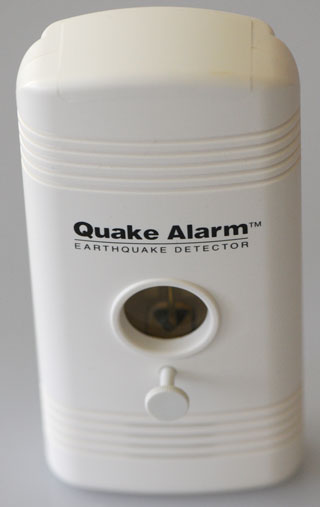
This one is made by jds Products andis their model QA-2000.
At a prior house I had a similar looking unit that was a true P wave (Wiki) detector to give earlier warning of a quake.
EarthQuake Alert
Atomic Bomb Test Ban
By using a high dynamic range and wide bandwidth ( 10 seconds to 10 Hz) seismograph the difference between an earthquake and an explosion can be detected. The Vela Uniform project (Wiki) investigated how to do this. Keywords: Long Range Seismic MeasurementsPatents
1552186 Seismometer John A Anderson, Carnegie Institution, 1925-09-01, - optical spot projection, cited by 14 patents1784415 Electrical Recording Seismograph, H. Benioff (Carnegie), Dec 9 1930, 340/870.16 ; 310/15; 340/870.31; 340/870.44; 346/107.1; 346/65; 367/179; 367/182; 73/654
2933715 Seismic Device,Beuermann, Apr 1960,
2269453 Device for Detecting Displacements, E.L. Gayhart, Jan 1942
2348225 Magnetic Seismometer, O.S. Petty, May 1944 - oil prospecting geophone
2576775 Seismometer System, F.D. Case (Diamond Inst), Nov 1951, - long period earthquake detection in small size
2683867 <See below>
2756406 Vibration Detector, G.S. Schurman (Calif. Research Inst), July 1956, - Frequency Response vs. Geophone mass - oil prospecting
2788512 Low Frequenc Seismometer, W.J. Reichert (Shell), April 9 1957,
2683867 Parachuted Radio Seismic Transducer, J.O. Vann (not assigned), July 13 1954, - for measuring polar ice
3225328 Transportable Seismograph, F Lecroart,
2111643 Seismometer, H. Salvatore (Western Geophysical Co), Mar 22 1938, - combine permanent magnets and coils - prospecting
2418953 Transducing System, R.W. Raitt
2519916 Inertial Electromagnetic Throat Microphone, D.W. Martin (RCA),
2470244 ELECTRICAL REPRODUCING STYLUS - for machine shop duplicating
2562983 Frequency Adjustable Seismic Wave Detector, D.H. Clewell, Aug 7 1951, - oil prospecting
2643367 MAGNETOSTRICTION SEISMOMETER, (Phillips Petroleum Co)
2663088 Pendulum and Acceleration Compensation System, R.T. Cloud (N. Am Geo)
2540796 VIBRATION TRANSLATOR, A.N Stanton
2671202 VIBRATION PICKUP, M.O. Petroff (Stewart-Warner), Mar 2 1954 - wheel balancing
2595067 INERTIA TYPE VIBRATORY PICKUP, J.A. Flint (Jeffrey Mfg), Apr 1952
2659065 SEISMOMETER, R.L. Cordell (Stanolind Oil)
3066526 UNBALANCE DETECTION APPARATUS, H.R. Tear (Stewart-Warner),- wheel balancing
3480808 POWER GENERATOR, F. Rieth (Packard-Bell) - probably for TV remote
4740775 Automobile burglar alarm, R. Price,
4584569 Motion sensitive security system, M.J. Lopez,
5323133 Method and apparatus for making electrical connection with a movable member, - loudspeaker
2390187 Seismic surveying, Joseph A Sharpe, Standard Oil and Gas, App: 1941-10-22, W.W.II, Pub: 1945-12-04, - Figs 7 - 9 are of a seismometer
------------------ Korean Conflict-----------
2533249 Seismic Detector, December 12, 1950, 310/25 ; 367/183; 73/496
2636160 Vertical Component Low Frequency Geophone, April 21, 1953, 318/680
----------------- Korean Conflict end -----------
2696592 Vib Pickup, December 7, 1954, 336/30 ; 335/285; 336/100; 336/136; 336/90; 73/654
2745085 Seismic Detector, May 8, 1956, 367/185 ; 310/14
2748370 Seismometer, May 29, 1956, 367/187 ; 174/77R; 267/160
2751573 App Chg Reas Freq, June 19, 1956, 367/183 ; 310/25
2754435 Voltage Generating Vibratory Pickup Devices, T. Ongaro, International R&D, July 10, 1956, 310/27 ; 367/183; 73/661
Publication number Priority date Publication date Assignee TitleUS1271864A 1917-08-13 1918-07-09 Thomas J Digney Submarine barrier.US2013993A 1931-02-21 1935-09-10 Texas Co Pneumatic vibration detectorUS2038101A 1931-02-18 1936-04-21 Texas Co Vibration detectorUS2062784A 1932-04-04 1936-12-01 William G Green SeismographUS2074043A 1932-07-29 1937-03-16 Standard Oil Dev Co SeismographUS2130213A 1935-10-23 1938-09-13 Texas Co Vibration detectorUS2272984A 1939-07-21 1942-02-10 Gulf Research Development Co SeismographUS2304738A 1939-06-29 1942-12-08 Socony Vacuum Oil Co Inc SeismographUS2307792A 1939-07-28 1943-01-12 Cons Eng Corp SeismometerUS2348225A 1940-02-13 1944-05-09 Olive S Petty Magnetic seismometerUS2372056A 1941-06-21 1945-03-20 Socony Vacuum Oil Co Inc Method and apparatus for recording seismic wavesUS2371973A 1944-01-10 1945-03-20 Socony Vacuum Oil Co Inc Geophysical prospecting apparatusUS2387223A 1943-02-06 1945-10-16 Research Corp Vibration pickupUS2636160A 1949-08-29 1953-04-21 Socony Vacuum Oil Co Inc Vertical component low-frequency geophone
2788511 Frequency Seismometer, E.H. Marshall, Texas Inst, April 9, 1957, 367/187 ; 267/161, - oil exploration
2788512 Frequency Seismometer, April 9, 1957, 367/14
2788513 Cable, E.T. Howes, United Geophysical Corp, April 9, 1957, 367/180 ; 174/102SC; 174/106R; 174/27; 174/71R; 310/338; 310/357; 367/154
2842752 Geophones, July 8, 1958, 367/182 ; 267/160; 336/100; 336/136
2923367 M App for Seismic sur, February 2, 1960, 367/34 ; 367/48; 367/58
2933715 Geophones, April 19, 1960, 367/184 ; 310/15; 310/27; 73/654
2939079 METHOD OF CALIBRATING AN ELECTROMAGNETIC, May 31, 1960, 324/537 ; 324/202; 367/13
---------------- Vietnam Era ---------------
2980042 Method for Planting Seismic Detectors, B. McCollum, April 18, 1961, 405/177 ; 111/199; 111/89; 343/719; 405/175; 405/183 - oil exploration
3020767 Linear Accelerometer, W.P. Kistler, KistlerInst Corp., February 13, 1962, 73/497 ; 267/160
3199072 Variable Oscillation Period Seismometer, August 3, 1965, 367/185
aimed at nuclear detection
3241375 Transducer, R.M. Canzoneri, Consolidated Electrodynamics Corp., August 24, 1965, 310/14 ; 310/15; 367/184; 73/654 - strain gauge type, instrumentation, tolerates hi G
3281543 Calibrator for microphones, Haile S Clay, Charles W Cantoni, Donald B Ricketts, GTE Sylvania, 1966-10-25, -"Geologists, seismologists, and petroleum and research engineers use acoustical data...", 0.1 to 20 Hz acoustic, not vibration - What microphone would this be for??? let me know (PS GTE in Mountain View) Guess: Nuclear Test Ban monitoring, infrasound
3296587 Intrusion detector system, Buford M Baker, TI, App: 1963-02-20, Pub: 1967-01-03 - See PSR-1 Patent
3451040 Spring Suspension for Low Frequency Geophone, W.P. Johnson III, Mark Products, June 17, 1969, 367/183 oil exploration - Sercel/Mark Products: L-4 is marked with this number
5,500 Ohms, 1 Hz, 45 dynes/Amp, 972 grams i.e. L-4C. They also make geophone testers.3545286 Holder which is Displaceable Along one Axis, L.A. Stenstrom, Philips, December 8, 1970, 248/604 ; 267/154; 267/160; 73/514.24; 73/654
25Jun22-eBay: Mark Products L-4 | 500 Ohms | 1.0 Hz | 956.1 gm | Seismometer Sensor,
Archive.org: Sercel\Seismometers - Geophones_brochure_Sercel_EN.pdf - Geophones_specifications_Sercel_EN.pdf -
L-4:
L-4 is an instrument quality 1-hz or 2-hz multi-purpose seismometer that is small, light, and economical. It is designed to yield the performance needed for scientific studies, yet has the ruggedness required for petroleum exploration work.L-22:
The L-22 miniature low frequency land seismometer is available in 2.0 hz models, and may be obtained with several different coil resistances as standard manufacture. Other coil values are available on special order.Geophone Tester Related Patents
2597005 Method of calibrating microphones, James M Kendall, Geophysical Res Corp, 1952-05-20, 73/1.83; 324/202; 367/141; 367/13; 381/58 - hydrophones
2923366 Seismic prospecting method, Edwin P Meiners, Glenn A Schurman, California Res, 1960-02-02, 367/37; 367/189; 367/180 -
3224246 Low frequency hydrophone calibration, Schloss Fred, Strasberg Murray, 1965-12-21, 73/1.83; 367/13 - pressure tank + shaker moves tank up/down
3744294 Acoustical transducer calibrating system and apparatus, T Lewis, R Cohn, NASA, 1973-07-10, 73/1.82; 381/150; 367/13 - air pressure for aircraft measurements
3858169 Geophone impulse tester, T Bardeen, Gulf Res, 1974-12-31, 367/140; 367/13; 367/58; 73/1.85 - applying an electrical impulse to a single sensor or string of sensors.
4441173 Very low frequency hydrophone calibration, James F. McEachern, US Navy, 1984-04-03, 367/13; 73/1.83 - motor makes LF waves
4909064 Impulse calibration of mechanical to electrical transducers, Richard D. Talmadge, US AF, 1990-03-20, 73/1.82 - hammer taps sensor
3577184 Low Distortion Seismometer, W.O. McNeel, Geo Space Corp., May 4, 1971, 525/342 ; 525/332.9; 525/333.1; 525/333.2; 525/359.1; 525/359.3; 525/359.5; 525/359.6; 525/361; 526/240
3662326 Subaudible frequency detection system, Paul S Dennis Jr, (BAE) Hazeltine, App: 1969-11-04, Pub: 1972-05-09, - for making geophone output of person walking audiable
3738445 Seismometer Spring Suspension System, Wilson,
3742441 Seismometer, T Riley, Mark Products, App: 1970-03-25, Pub: 1973-06-26, - lower distortion
4323994 Geophone Spring, J.M. Coogler, Geosource, April 6, 1982, 367/183 ; 267/158; 267/161; 367/187
4458344 Tapered Geophone SpringJ.M. Coogler, Geosource, July 3, 1984, 367/183 ; 267/161; 367/187
4623991 Delta Shaped Geophone Spring, F.A. Vitringa, Geosource, November 18, 1986, 367/183 ; 267/161; 367/187
5113375 Method and apparatus for testing geophones
5134593 Geophone Spring, R.M. Logan, Western Atlas Intl Inc., July 28, 1992, 367/187 ; 267/141.3; 367/183
6658362 Method and apparatus for testing components
6816434 Seismic detection
WO2014015271 Micro-geophone, Daniel Woo, Geospace Technologies, 2014-01-23, -
Warning Alarm Patents
540
 Specific
condition
 686.1
 Position responsive
 690
 Geophysical
(e.g., fault slip)
 5633463 Earthquake detector, May 1997, 73/654 ; 181/122; 200/61.45R; 340/690; 367/182 - all mechanical
5837951 Inertia switching device, acceleration responsive device and method of Making Acceleration Responsive Device, November 1998, 200/61.45R - ball in cage switch
6121888 Earthquake detector, September 2000, 340/690 ; 340/540; 340/686.1 - long spring sensor/switch
| 2689341 | SAFETY DEVICE FOR INDICATING SHIFTING | September 1954 | 340/690 ; 200/51.11; 200/61.45R |
| 4262289 | Seismic tremor sensor alarm | April 1981 | 340/690 ; 200/61.51; 74/89.14; 74/89.1 |
| 4297690 | Earthquake alarm system | October 1981 | 340/690 ; 200/61.49; 200/61.51; 340/669; 340/689 |
| 4359722 | Earthquake detection system with pendulum switch | November 1982 | 340/540 ; 307/117 |
| 4484186 | Earthquake indicator | November 1984 | 340/689 ; 116/303; 200/61.52; 33/391; 33/402; 340/690; 73/652 |
| 4689997 | Motion detector suitable for detecting earthquakes and the like | September 1987 | 73/652 ; 181/122; 340/580; 340/690; 367/182; 73/65 |
| 4801793 | Orientation indicating
device (camera portrait or landscape) |
January 1989 | 396/50 ; 396/287 |
| 4945347 | Motion and orientation responsive device for seismic, intrusion, and tilt | July 1990 | 340/689 ; 200/61.45R; 340/690 like Quake Alarm |
| 4978948 | Combined earthquake sensor and night light | December 1990 | 340/690 ; 340/321; 362/253; 362/806 |
| 5418523 | Earthquake motion detector alarm | May 1995 | 340/690 ; 200/61.45R; 200/61.51; 340/66 |
| 5596183 | Seismically activated appliance switch | January 1997 | 200/61.45R ; 200/61.48; 200/61.51; 307/117; 340/690 |
| 5633463 | Earthquake detector, | May 1997 | 73/654 ; 181/122; 200/61.45R; 340/690; 367/182 |
| 5644300 | Seismoscopic detector | July 1997 | 340/690 ; 340/540; 340/691.5; 340/693.5 |
| 5867099 | ----- bad patent
no.------ |
February 1999 | |
| 5929767 | Earthquake detector and alarm | July 1999 | 340/690 ; 200/61.45R; 340/601; 340/689 |
7006000 Earthquake detecting and warning device, February 28, 2006, 340/690 ; 200/61.52; 73/579; 73/594; 73/649; 73/658 - inverted bowl
Seismograph Service Corporation (patents)
The TAGS Ship: How Did Lorac Work? - AN/SRN-7
2493534 Testing device for seismic signal apparatus, James E Hawkins, Seismograph Service Corp, App: 1947-06-13, Pub: 1950-01-03, -
2648979 Transducer testing apparatus, Jesse R Cornett, Seismograph Service Corp, App: 1946-08-09, Pub: 1953-08-18, -
2757750 Apparatus for generating seismic waves, James E Hawkins, William E Pugh, Seismograph Service Corp, App: 1948-10-08, Pub: 1956-08-07, -
2513314 Geophysical prospecting system, James E Hawkins, Seismograph Service Corp, 1950-07-04, - LORAC positioning system
2513315 Radio position determining system, James E Hawkins, Seismograph Service Corp, 1950-07-04, - LORAC positioning system
2513316 Radio survey system, James E Hawkins, Seismograph Service Corp, 1950-07-04, - LORAC positioning system
2513317 Radio position determining system, James E Hawkins, Seismograph Service Corp, 1950-07-04, - LORAC positioning system
2513318 Radio position finding system, James E Hawkins, Seismograph Service Corp, 1950-07-04, - LORAC positioning system
2513319 Geophysical prospecting system, James E Hawkins, Seismograph Service Corp, 1950-07-04, - LORAC positioning system
2513320 Radio position determining system, James E Hawkins, Seismograph Service Corp, 1950-07-04, - LORAC positioning system
2513321 Radio location system, James E Hawkins, Seismograph Service Corp, 1950-07-04, - LORAC positioning system
2513322 Radio location system, James E Hawkins, Seismograph Service Corp, 1950-07-04, - LORAC positioning system
2652558 Radio location system, James E Hawkins, Seismograph Service Corp,1953-09-15, - LORAC positioning system
2652559 Radio location system, James E Hawkins, Seismograph Service Corp,1953-09-15, - LORAC positioning system
2652560 Radio location system, James E Hawkins, Seismograph Service Corp,1953-09-15, -LORAC positioning system
2652561 Radio location system, James E Hawkins, Seismograph Service Corp, 1953-09-15, -LORAC positioning system
2652562 Radio location system, James E Hawkins, Seismograph Service Corp, 1953-09-15, - LORAC positioning system
Earthquake Early Warning
California Integrated Seismic Network - Earthquake Early Warning -
Quake-Catcher Network
They also has an Android app that uses the 3-axis g sensor
combined with the magnet compass when the phone is sitting
unused on the charger to report quakes.
This is better than the USB hardware which should be oriented
to magnetic North.
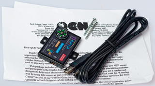
The sensor contains a 3-axis MEMS accelerometer and a USB interface.
http://www.youtube.com/user/QuakeCatcherNetwork
Sensor
ONavi B 16 bit.
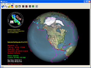
The QCNLive display of the 3 sensor outputs does auto scale,
so there should be some benefit from mounting the sensor
away from the house.
USB-CAT5 adapters & 100" CAT5 cable
This does not work. Why? Ans: handshake timing limits
cable length. But, an active USB extension cable does
work and these could be cascaded.
1. can the USB cable be extended say 100 feet to allow sensor location far from the house?
2. does the software contain a circular memory so that the data can be uploaded at a later time if there's a network problem in real time?
3. Is there any intelligence in the sensor, i.e. a micro controller?
4. Is there provision for adding different sensors, like those on this page? Yes & No. There's a list of supported sensors, but they are all USB based. There's not provision for a 2-wire input type sensor like the Hilger-Watts.
Software
There are three programs that need to be downloaded and
installed (Instructions)
- Boinc (Berkeley Open Infrastructure for Network
Computing)- allows
your computer to talk to the server over your internet
connection.
Add QCN to “My Projects”:
Select “Next”.
Under “Project URL” type the following: qcn.stanford.edu/sensor
USB driver for the specific sensor you have
QCNLive - program running on your computer
File\Local Settings - Lat, Lon, Ele, etc.
Windows Firewall needs to have Boinc added as an exception.
Earthquakes
Earthquake 25 Sep 2012 8:15 am Ukiah
The electronic equipment was swaying North-South and it
almost fell over.
Very strong shaking.
USGS
web page. M4.5
