Sonobuoys & Outdoor Intrusion Detectors
Brooke Clarke 2011 - 2025
Background
Sonobuoys
Types of Sonobuoys
CNU-239/E Shipping Tube
A Size
Operational Life
Radio Transmitter
Radio
Channels
Black
Box Beacon Transmitter
DIrectional Frequency
Analysis & Recording type acoustic sensor (DIFAR)
Reserve Batteries
Reserve Battery Patents
Light, Emergency Sea
Rescue Marker
Table of Sonobuoys
SSQ-36
SSQ-53B
Battery
SSQ-937B
Sonobuoy Aircraft Systems
Receivers
ARR-52
Others
Outdoor Intrusion Detectors based on
Sonobuoy Technology
Link between Vietnam
Intrusion Detectors and Navy
Construction
Mines for Noise
1st Generation
ADSID
ID-1721 Indicator WANTED TO BUY
GSQ-154
GSQ-160
SLOT Buoy
Patents
Wave
Buoy
Sonobuoy
SONAR
Dr. Breed & Hughes
Launching Sonobuoy
Magnetic Anomaly Detector (MAD)
ASQ-8
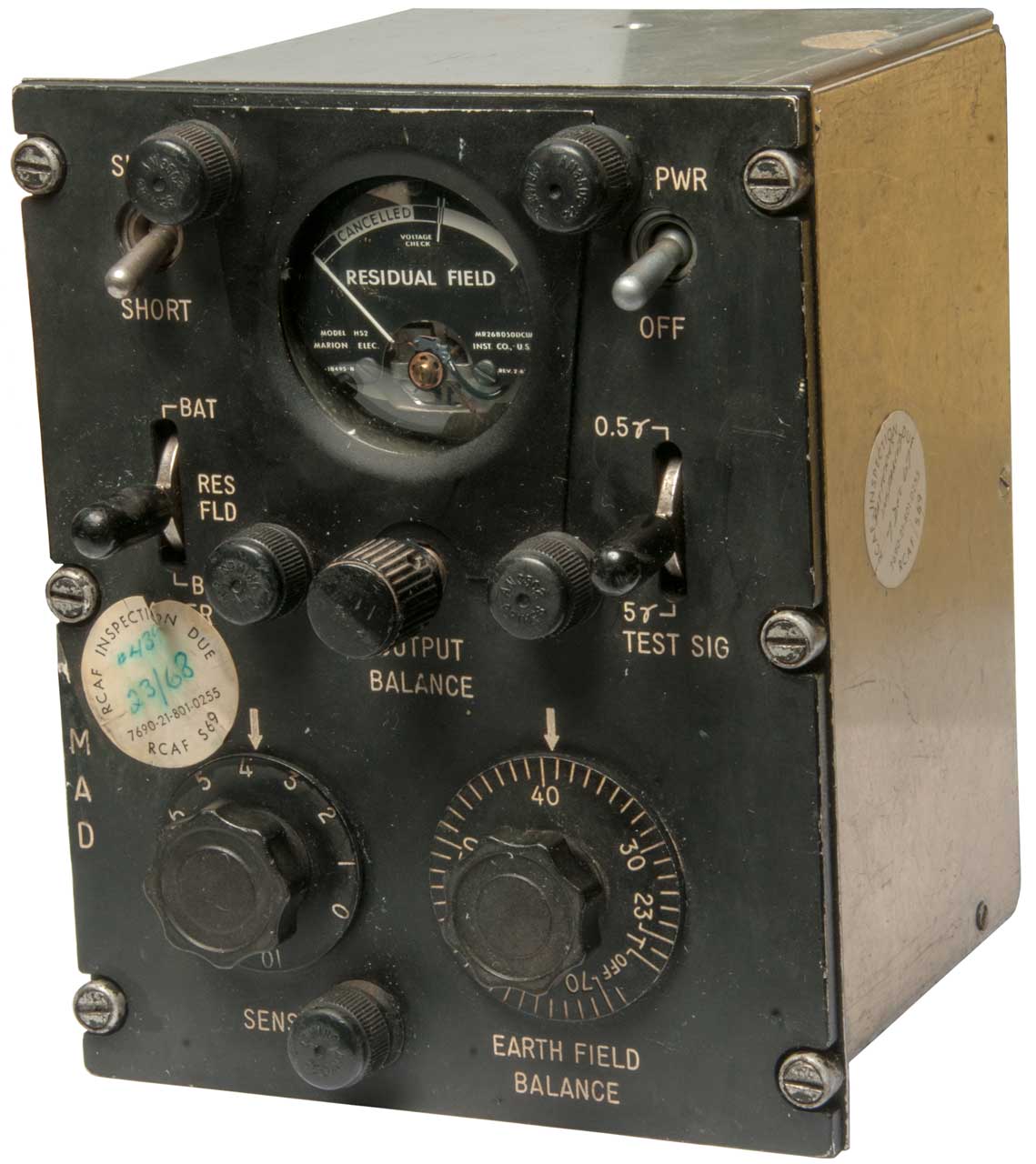
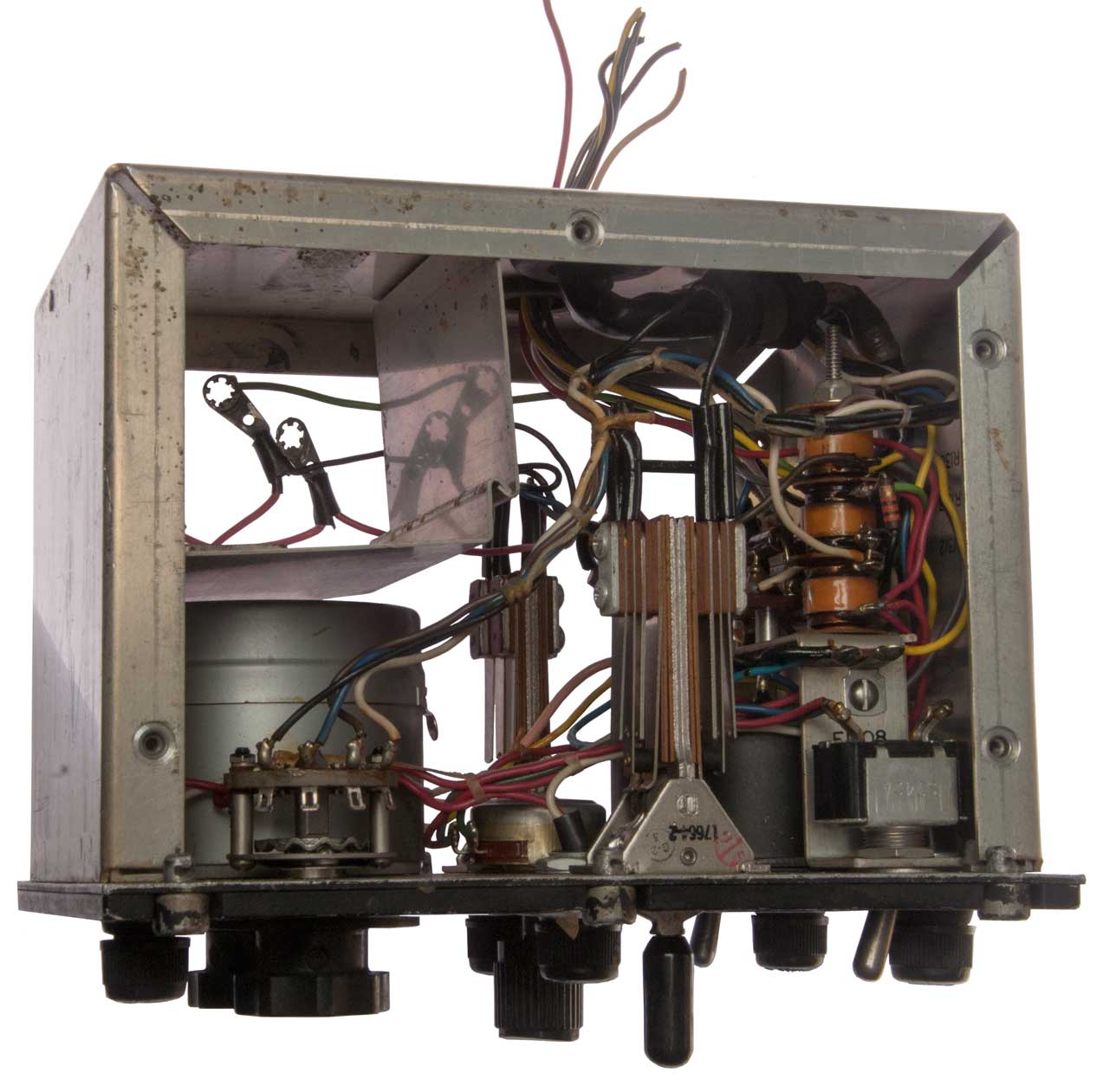
C820 Control Panel
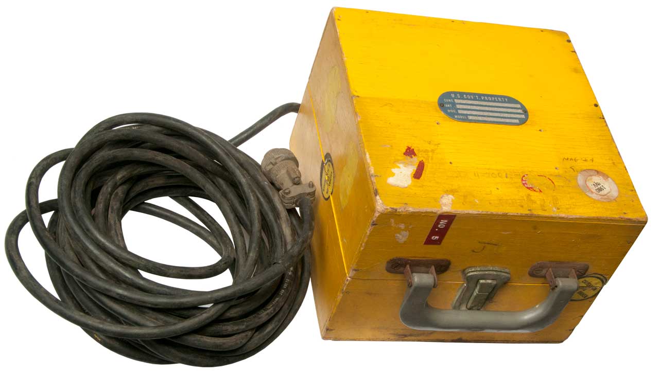
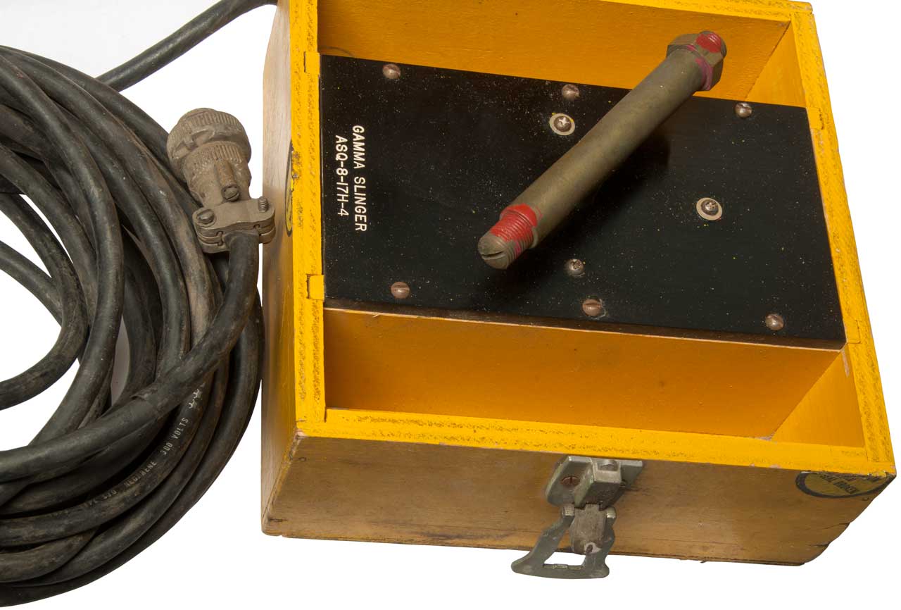
17H-4 Gamma Slinger
Black Crow ASD-5
References
MAD patents
SONAR Countermeasures
Sound Ranging
Hydrophones
Patents
Seismometer
Hazeltine Hydrophone and
Retainer Assembly A22267-1
Roswell Connection
Unknown Sonobuoy - What is it?
Unknown
Sonobuoy No. 2 (Greece)
Underwater Communications
BQC-1
Underwater Telephone
WQC-2
Underwater Telephone
Communication Buoy
JANUS
Acoustic release
Submarine Missile
Hanger
Submerged Signal
Ejector
UAV
Global
Hawk
Command Activated Sonobuoy
(CAS)
Sonobuoy
Training
Related
P-3C Systems
Submarine Laser
Communications
SOSUS
Missile
Launch Patents
Movies
Books
YouTube
Related
Links
----------------
Bathythermographs moved to the Bathythermographs
web page.
Niskin
Bottle moved to the Bathythermographs
web page
SSXBT Model ST-1 moved to the Bathythermographs
web page\SSXBT.
Background
During the Vietnam era the
"electronic battlefield" (book: Military Communications: A Test
for Technology) was developed and it included various outdoor
intrusion alarms (my name for these devices). Some, like the
PSR-1 Seismic Intrusion Detector, used
wire between the sensors and the main unit and others used a radio
transmitter in the sensor and the main unit was a radio receiver.
The frequency spectrum has allocations for different users (see
Frequency Allocations). One band is
used by aircraft for communication and navigation (108 to 136
MHz). A number of Vietnam era outdoor intrusion sensors used
this band.
Another band is used for sonobuoy operations by the Navy (162.25
to 173.50 MHz with 31 channels with 375 kHz spacing). This
page is about these outdoor intrusion sensors.
Department of Defense Training Film
MF11-5514
Bugging
the Battlefield pt1-2 1969 Defense Department Electronic
Eavesdropping Vietnam War
Bugging
the Battlefield pt2-2 1969 Defense Department Electronic
Eavesdropping Vietnam War
Electronic Eavesdropping,
Vietnam War: "Bugging the Battlefield" 1969 Defense Department
(30:28) - combined part 1 & 2
Submarines & the Noises they Make
The early work on SOund Navigation And Ranging (Wiki:
SONAR), which was
named after RAdio Navigation And Ranging (Wiki:
RADAR), was done
utilizing audio frequencies were an operator would listen on
headphones (for those systems that used stereo) or a
loudspeaker. The first sonobuoys also used audio with a
human operator listening to the sound. This is called
passive SONAR (code name Jezebel). There are no pings and
whoever is doing the listening is not giving away their presence
or position. When it works it's the preferred method and is
by far the most common. In the 1950s the SOund SUrveillance
System (Wiki:
SOSUS,
my page)
which makes use of LOw Frequency Analysis and Recording (LOFAR)
rather than the use of human audible sound was put into
service. This worked on snorkeling diesel electric subs (
Wiki)
and on nuclear powered subs like the Soviet Hotel (
Wiki),
Echo (
Wiki)
& November (
Wiki)
class subs (HEN).
Active SONAR comes in two flavors, the most commonly known is the
active ping like in any movie involving submarines. A ping
is sent out and the time measured until it returns. The
early pings were audible to humans, later ultrasonic pings were
used and later still the frequency of the ping changed it into a
chirp. If the propagation speed is known the distance to the
target can be calculated and with the later types the radial speed
of the target can be determined. The less well known active
SONAR method (code name Julie) involves setting off an explosion
of a couple of pounds of TNT using either the Mk-15 (Mod-12) or
Mk-61 Signal Underwater Sound (SUS). The explosion generates
a spike in the underwater pressure which is similar to a ping at
all possible frequencies, it's the most useful type of ping, but
can only be used occasionally because it requires a small bomb for
each pulse.
Modern diesel electric subs are very quiet when running on
battery power underwater and going slow. The explosive type
active SONAR is good at detecting these subs.
It turns out
Radiosondes
have a very strong relationship with Sonobuoys and
Pilot
Balloons.
Sonobuoys use water activated batteries as are most radiosonde
batteries and they both use VHF or UHF radio transmissions to send
data/audio. They both have an operational life measured in
minutes or hours, not days or any time longer. Both are made
to be light weight. They are both considered single use,
i.e. expendable.
Pilot
Balloon (PIBAL) are part of learning about the upper air as
are radiosondes. They overlap in that PIBALs do not carry a
radiosonde, but are used by themselves or with a PIBAL light for
low light conditions.
Sonobuoys
The word sonobuoy is a
portmanteau of sonar and buoy according to Wiki.
The first U.S. sonobuoy was the CRT-1
used in W.W.II. Like the Mk 24 "Fido" Mine (Wiki) it
could only hear cavitating propellers.
Submarines Diving
In most movies about submarines
there is the diving practice where the captain says "Dive . . .
Dive . . . Dive" and you hear a Klaxon horn (Wiki)
sound. A big thing is made of timing how long it takes to
dive to some depth. This comes about because aircraft
specify how they turn by how long it takes to fly a full circle.
For medium size airplanes this might be two minutes. Note
the rate of turning is specified by the time for a circle, not
bank angle or the diameter of the circle. So if an
aircraft flies over a submarine and makes a tight circle to come
back to attack it a second time the submarine has maybe 2
minutes to dive to safety.
This emergency dive process will go faster if the submarine is
full speed ahead since there are some similarities between
aircraft and submarines in the sense of how they respond to the
elevator. At full speed ahead the propeller(s) will
cavitate (Wiki)
which makes a lot more noise than normal running. This
extra noise was needed in order for the CRT-1 Sonobuoy and the Mk 24
"Fido" Mine (homing Torpedo) to work.
Types of Sonobuoys
ADAR: Advanced Deplorable Acoustic Receiver
ADLFP: Advanced Deplorable Low Frequency
Projector
ALFEA: Active Low Frequency Electro-Acoustic
BARRA: means Listening in an indigenous Australian language - The
Barra Sonobuoy System, Barra
Sonobuoy Design, horizontal array
BT: Bathythermograph
CAMBS: Command Activated Multi-Beam Sonobuoy
CASS: Command Activated Sonobuoy System
CFS: Command Function Select (set function with 2-way radio when
buoy is in water)
CO: Calibrated Omni type acoustic sensor (5 - 20 kHz)
CSO: Constant Shallow Omni type acoustic sensor (30 - 5000 Hz)
DICASS Directional Command Activated Sonobuoy System
DIFAR: DIrectional Frequency Analysis & Recording type
acoustic sensor (5 - 2400 Hz)
EER: Extended Echo Ranging - uses small explosion as sound source
see patent 2402391
EFS: Electronic Function Selector (RF Chan, Life, Depth, Sensor
type, AGC)
HIDAR: High Dynamic Range DIFAR
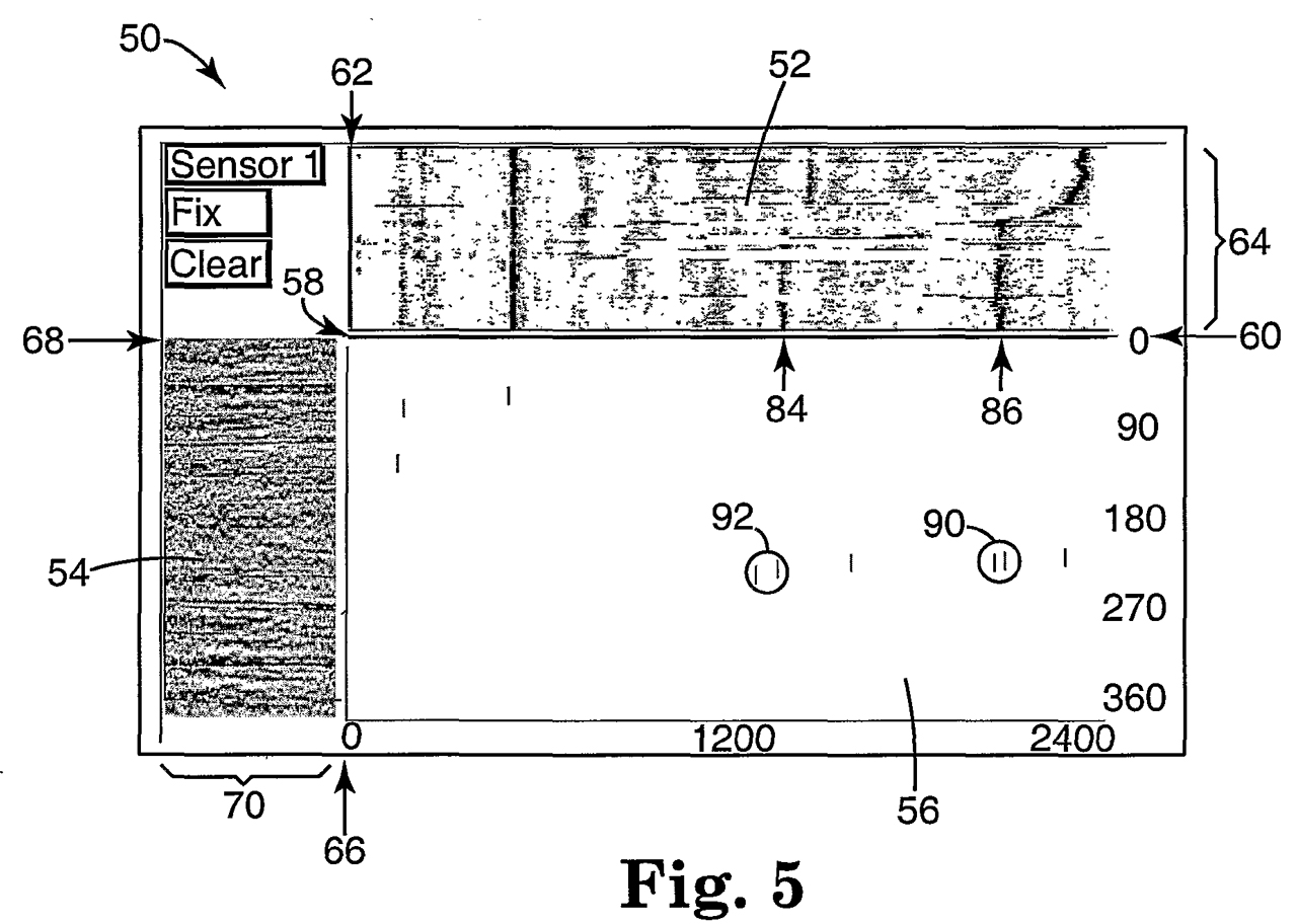
LOFAR: LOw Frequency Analysis & Recording - low cost, the
waterfall display good for classifying a contact
RDRH: Rotating Directional Receiving Hydrophone
REFS: optical
Remote Electronic Function Select (either while in launch tube
(easy) or in water (requires laser))
RO: Range Only
The word sono-buoy is based on sound
and a floating object. See the
CRT-1 web page for some history
on acoustic sonic buoys.
Sonobuoys (
Wiki) have been
around since about May 1941 when P. M. S. Blackett, head of the
British Admiralty committee for antisubmarine measures, proposed
the idea. In June 1942, the
AN/CRT-1
became the first operational sonobuoy which was launched from a
ship in a convoy, and on July 25, 1942, the first successful
launch of a sonobuoy from an aircraft was made from a U.S. Army
B-18 bomber (
Wiki).
(from:
Not
Ready for Retirement: The Sonobuoy Approaches Age 65 by
Holler, Roger, Horbach, Arthur, McEachern, James).
They have nomenclature SSQ-nn. They are a part of
anti-submarine warfare (
Wiki).
"All sonobuoys currently in inventory are normally launched from
standard A-size tubes via pneumatic, free fall, or a Cartridge
Actuated Device (CAD). Shipboard personnel may also launch
them by hand or Over the Side (OTS). All are powered by either
salt water activated magnesium or silver chloride, lithium
chemistry, or thermal batteries and are designed to scuttle at
some point after usable or selected life expires." from
Approved Navy Training System Plan, for the Consolidated
Sonobuoys. N88-NTSP-A-50-8910B/A SEPTEMBER 1998
There's a problem with airborne sonobuoy receivers being used
with
MAD. MAD works best when the
plane is flying at about 500 feet. This is also true for the
periscope detecting RADAR. BUT . . . .
The sonobuoy receiver will have relativity short rang when the
plane is at 500 feet. Much higher would allow better
sonobuoy coverage. Not sure what's an optimum altitude for
dropping sonobuoys. The new Navy P-8 (
Wiki)
no longer uses MAD and flies much higher, both for more sonobuoy
area coverage and for better fuel consumption than it gets when
flying low. The P-8 has the AN/APY-10 RADAR (
Wiki) but as
far as I can tell it does not work as well at high altitudes
because the ocean surface scatter gets poorer at higher
altitudes. The poorest result is looking straight down on
the water.
CNU-239/E Shipping Tube
This may be the standard shipping container for A size
sonobuoys. It's 45" long and an octagon 6-3/4" across the
flats. One end unscrews and when shipping the cap is tapped
to the main body. The weight depends on what model in
inside.
|
|
Transport
Canada SU
0850 makes provision for shipping experimental
sonobuoys in this container.
But there are limitations:
(a) all the dangerous goods are contained within the
aluminum body of the experimental sonobuoy described by
drawings no. 200896, 200898, 200702, 200671, 200836 and
200837 deposited by Ultra Electronics Maritime Systems,
a division of Ultra Electronics Canada Defense Inc. on
Transport Canada's Transport Dangerous Goods Directorate
file A 4069-0850;
(b) the sonobuoy contains a single UN0454 Igniter
having a net explosive quantity equal to or less than
0.15 g;
(c) the sonobuoy contains a maximum of 2 cylinders of
UN1013, Carbon dioxide, each having a capacity equal to
or less than 0.120 L;
(d) the sonobuoy contains a quantity equal to or less
than 40 "C" size lithium batteries that meet the
requirement of paragraph (1) of Special Provision 34 of
Schedule 2 of the Transportation of Dangerous Goods
Regulations;
(e) the sonobuoy is packaged in the military
performance specification plastic shipping container
type CNU-239/E specified in the drawing 012-159-0009-00
deposited by Ultra Electronics Maritime Systems, a
division of Ultra Electronics Canada Defence Inc. on
Transport Canada's Transport Dangerous Goods Directorate
file A 4069-0850;
|
A Size
Modern sonobuoys have an outside diameter of 4-7/8" (fit 4-15/16"
launch tube commonly called 5 inch) and are 1 yard long
(36"). The max weight is 39 pounds.
This is a convenient size for one man to handle on a P-3 aircraft
(
Wiki).
The larger sizes are not easy to handle. There are smaller
sizes based on getting some integer number of them inside the A
size outline. 3 each is called "F" and 2 each is called
"G". The other sizes are pretty much not used in volume.
Operational Life
Sometimes the service life can also be programmed prior to launch
for 1, 3 or 8 hours. After that time the sonobuoy will sink
to the bottom. This can be made to happen by exploding a
resistor (acting as a squib) applied to the float bag.
Radio Transmitter
A VHF vertical whip antenna is used. One feature of this
type of antenna is that there's a null directly above the buoy so
when an aircraft directly overflys the buoy there's a
characteristic signal drop out. This allows confirming the
buoy location. The 1 Watt transmitter is FM modulated and
covers an audio bandwidth of 10 Hz to 20 kHz (about the same as a
Hi-Fi system or entertainment FM radio). Note that there is
no provision to hear the 37 k Hz ping made by Cockpit Voice
Recorders or Flight Data Recorders. The FAA and Navy need to
coordinate this.
Sonobuoy Receivers & Radio Channels
See the VHF part of the
Frequency Assignment table for some
common ways the spectrum is used. For example, FM
broadcast band is 88 to 108 MHz, 108 to 136 MHz is reserved for
aircraft communications and navigation. 136 to 174 is
called the High VHF band (the common "Scanner" band), the old
analog TV channel 7 was 174 to 180 MHz.
In the book US Naval Weapons, Norman Friedman, 1983 (
Ref 19) it's
mentioned that during W.W.II the
CRT-1 operated in the frequency
range of 67 to 72 MHz and that post war sonobuoys operated in
the 162.25 to 173.5 MHz range.
Generation Zero
The CRT-1 Sonobuoys
started out working in the VHF low band. First with
six channels between 62.9 and 66.9 then another six channels
were added in the 67.6 to 71.7 MHz range. That's a total
of twelve channels. This was during W.W. II.
Note: The eBay listing for a sonobuoy receiver
"R-156/ARR-16B Sonobuoy Receiver 62-72 MCs." is in
error by leaving off the "1" in front of the frequency.
R-156/ARR-16B covers 162 - 172 MHz.
It turns out the eBay listing was correct. Note that the
new VHF high band is pretty much 100 MHz higher than the prior
VHF low band.
1st Generation
It appears that the first generation sonobuoys only had 16
channels spaced 0.75 kHz apart between 162.25 and 173.50.
This was probably done using a single
crystal
in tube type electronics circuit.
2nd Generation
At some point (When?) the channel spacing was cut in
half. At that time to maintain channel number comparability
with the old system, the new channels were added in between the
old channels as shown in the
table. (chan 1) 162.25 to
173.50 with spacing of 0.375 MHz.
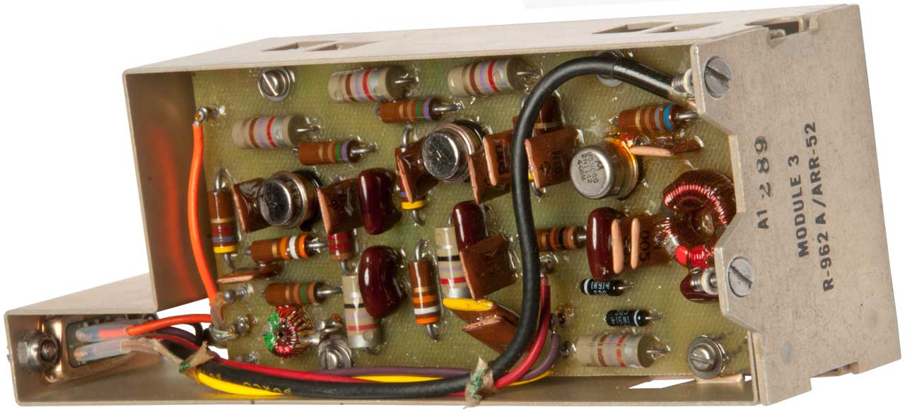
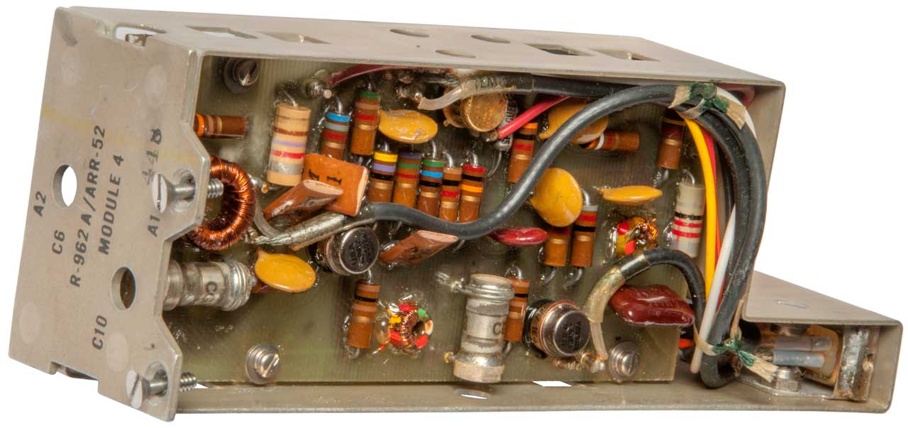
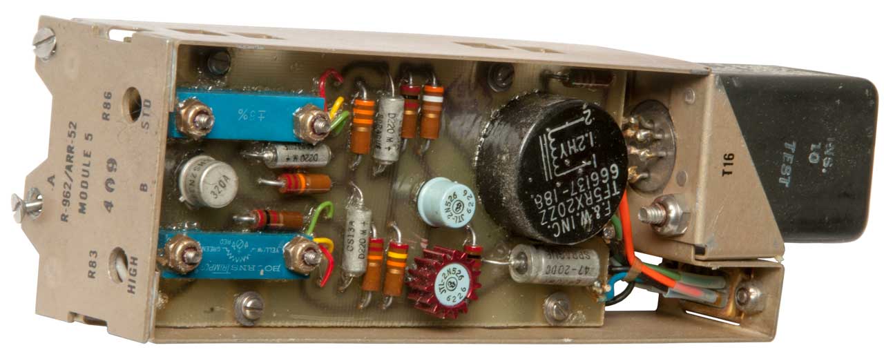
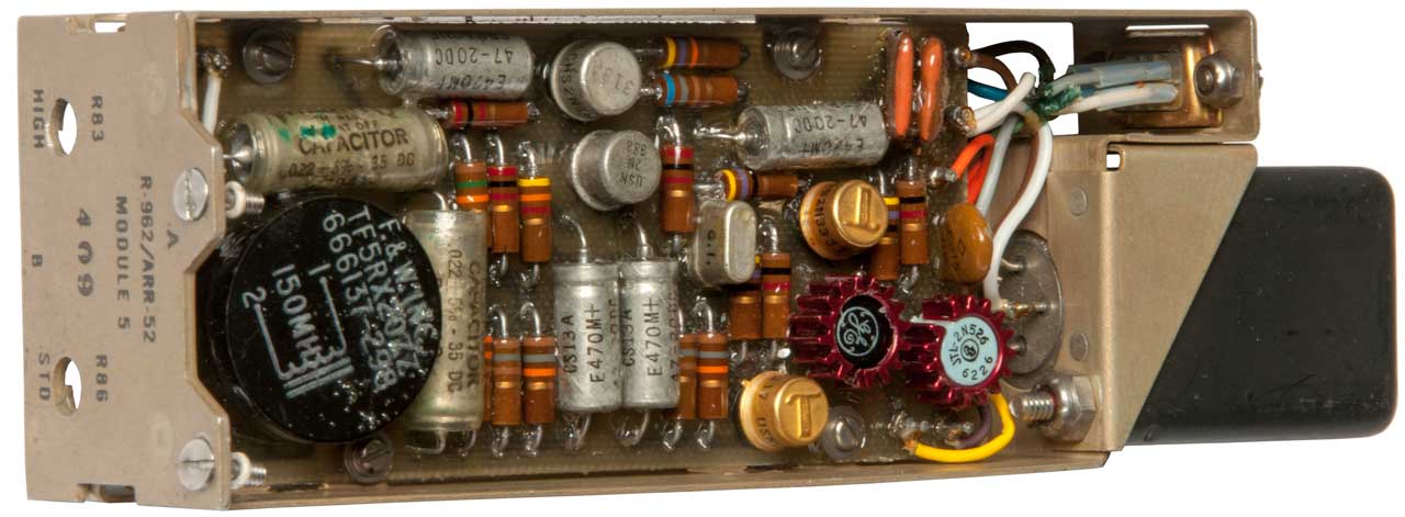
The
R-1170 ARR-52A sonobuoy
receiver has 31 crystal controlled channels.
This is the time frame of NAVAIR 28-SSQ-500-1 (1976).
Sonobuoys
Sonobuoy
SSQ-
|
Channels
|
41, 41A, 41B, 38, 50, 53,
57, 62
|
1-31
|
36
|
12, 14, 16
|
71
|
3, 5, 7
|
47A, 47B
|
1 to 12
|
3rd Generation
At some point (1980?) the total number of channels was increased
to 99 by adding channels starting at 136.000 MHz (chan 32) and
going to 161.125 (chan 99) with the same 0.375 MHz channel
spacing. Is there a channel 00? No only 1 to 99.
So the band plan in frequency order is, the new lower
frequency channels from 136.000 to 161.125, skipping 161.500 (now
Chan 100) and 161.875 (now Chan 101), then the 2nd generation
channels from 162.250 (chan 1) to 173.125 MHz (Chan 31).
In Channel number order:
Chan 1: 162.250 to Chan 31: 173.125; Chan 32: 136.000 to Chan 99:
161.125.
The USQ-46 receiver has 3000 channels with a 6.25 kHz channel
spacing.
If the received frequency is below 162.000 MHz then the Freq_MHz =
145.525 + <chan#> * 0.00625,
if the frequency is equal or greater than 162.000 then Freq_MHz =
162.000 + <chan#> * 0.00625.
So there's a strong sonobuoy flavor to how the USQ-46 does channel
assignment.
If you know about this,
tell me.
The difference in channel spacing = 375 kHz / 6.25 kHz = 60
exactly.
USQ-46 Channel 1 = 145.53125 or 162.00625
This is a beacon transmitter that just transmits a narrow
pulse in the sonobuoy RF frequency range. But, the
signal requires a receiver with about a 150 kHz channel
bandwidth.
Since the only information it sends is it's center frequency,
probably one of a small list of possible frequencies and one
of two possible duty cycles the process gain is extremely
high.
During the Vietnam era there were airplanes circling over
areas where ground based sensors were placed to relay the VHF
sensor signals to a ground station (Wiki).
This page was made because of the similarity of ground based
intrusion sensors and sonobuoys. They both work the same
way and both have the same reception requirements.
My guess is that today there is a satellite system doing the
same thing. This system would receive in the 136 to 173
MHz range and use digital IF processing, similar to what's
done in the HP 4395A combined spectrum
network and impedance analyzer. If that was the
case then it would be straight forward to have the ability for
this receiver to receive not only sonobuoy signals but also
the waveform used by the Black Box.
This makes sense in that the system would have world wide
coverage without the need to have planes circling 24/7 like in
Igloo White.
The WiNRADiO MS-8118/WSB Sonobuoy Telemetry Multichannel
Receiving System (WiNRADiO)
covers 136.000-173.500 MHz (custom frequency ranges available)
with an IF bandwidth of 30 kHz @ -6 dB.
They also have a WiNRADiO AX-61S
Sonobuoy Telemetry Antenna that covers 135 to 175 MHz.
The G315i receiver can be ordered with an optional hardware wide
band demodulator that's the same as in the sonobuoy receiver: WR-G315i
Receiver Options or for the WR-G315e
Receiver Options .
Note the black box beacon transmitter may be associated with the
SEAL Delivery Vehicle (Wiki: SDV).
That would be perfect for receiving the Black Box signal (thanks
to Chip Veres) for letting me know about the MS-8118. But
this raises a new question, what else generates such a wideband
signal?
The transmission frequencies of some black box units are:
164.5375 & 164.5875 MHz. Note neither of these is on
channel 4 (164.50 MHz) and they differ by 50 kHz, not likely an
accident.
Distributed Sensor Networks,
Second Edition: Image and Sensor Signal Processing (Chapman
& Hall/CRC Computer and Information Science Series)
Iyengar, S.
Sitharama- book on order 14 Nov 2015 has info on Igloo White
and may have some insights into the satellite system?
Sonobuoy Frequency
Table
Chan
|
Freq
|
Chan |
Freq |
Chan
|
Freq
|
1
|
162.25
|
6 |
166.00 |
11
|
169.75
|
17
|
162.625 |
22
|
166.375 |
27
|
170.125 |
2
|
163.00
|
7
|
166.75 |
12
|
170.50
|
18
|
163.375 |
23
|
167.125 |
28
|
170.875 |
3
|
163.75
|
8
|
167.50 |
13
|
171.25
|
19
|
164.125 |
24
|
167.875 |
29
|
171.625 |
4
|
164.50
|
9
|
168.25 |
14
|
172.00
|
20
|
164.875 |
25
|
168.625 |
30
|
172.375 |
5
|
165.25
|
10
|
169.0 |
15
|
172.75
|
21
|
165.625 |
26
|
169.375 |
31
|
173.125 |
|
16
|
173.50
|
Channel 15 (172.75 MHz) is used as an emergency search and
rescue frequency.
Command Function Select (CFS)
The aircraft can transmit to the sonobuoy to change the commands
while it's floating in the water which is much better than the old
way of making the command decisions prior to launch.
The UHF frequencies used for this are: 282.900, 291.300, 291.400,
291.500 MHz
Receivers
Directional Frequency Analysis &
Recording type acoustic sensor (DIFAR)
These buoys use directional
hydrophones (
Wiki)
covering 5 or 10 Hz to 2400 Hz combined with a magnetic bearing
sensor and transmit this information.
They can be used to passively listen, to listen for reflected
pings or the shock wave from a small explosion.
Whale researchers use them (
Tools
> DIFAR Sonobuoys).
Because the lower frequency limit is below Hi-Fi audio, and
the upper frequency of 24 kHz is above the 10 kHz upper end,
consumer grade tape recorders (Wiki)
could not be used so instrumentation type recorders were used
like the
With the advent of Digital Audio Tape (Wiki:
DAT) recorders the DIFAR signal could be recorded on a
DAT tape.
The following is a frequency spectrum of the DIFAR signal with
a voice channel added for use with a DAT tape recorder.

Analog circuitry, like using the LM1496 Balanced
Modulator-Demodulator can be used to manipulate these signals.
general
Note seismic sensors
(geophones) respond to frequencies below 10 Hz so there's an
overlap with DIFAR and other hydrophone frequencies.
DIFAR Patents
3093808 Air-dropped miniature
sonobuoy, Gimber
George A, Scarcelli
Albert F, Tatnall
George J, Secretary
of the Navy , Jun 11,
1963, 367/4, 441/33, 441/25, 343/709, 455/99 - Prior
art sonobuoys were 3' long, 5"
diameter and weighed 16 to 20 pounds
limiting aircraft time on station and
had a max depth of about 50'.
This one is 15" long, about 3" dia and
weighs about 5 pounds with a max depth
of 300'. also see 3047259
Speed brake retarding mechanism for an
air-dropped store, George
J Tatnall, Albert
F Scarcelli, Navy,
1962-07-31, -
3116471 Radio sonobuoy system, Jesse
J Coop, Dec 31, 1963,
367/3, 367/5, 367/113, 367/101, 367/126, 367/115, 318/638 -
In
the present invention a multi-beam directional
hydrophone is utilized in a radio sonobuoy
system whereby an immediate quadrant location
and an accurate distance measurement of a
reflecting object from the multi-beam
directional sonobuoy can be obtained from a
single pressure pulse generated in the water
area of interest. - DIFAR
3444508
Directional sonar system, Ernest
A Granfors, Don
L Loveless, Charles
F Boyle, Harry
W Kompanek, Sparton,
1969-05-13, - DIFAR sonobuoy
3727177
Short schuler attitude/heading reference system,
F Fuller,
D
Walters,
Navy,
1973-04-10, - orthogonal flux gate magnetometers mounted on a
compound pendulum
3818523 Steven
L. Stillman
3987404
Underwater Direction Finding System is the patent that defines
how a directional (the DI in DIFAR) sonobuoy can be made.
3987404
Underwater Direction Finding System, Sanders, (filed:
Nov 3 1967) Issued: Oct 19, 1976, 367/3;
367/125;
367/126
-
"An underwater direction
finding system includes a pair of directional
hydrophones and a compass in a novel arrangement which
associates the signals from all three elements with a
single subcarrier. Subsequent demodulation of
the subcarrier signals in an airplane or ship then
provides directional information directly referrenced
to the earth's magnetic coordinates."
Calls:
| US2754493 |
Indicator for
Sound Direction Finder
|
Feb 4, 1955 |
1956 |
|
LIPPEL |
| US2837730 |
Deflection
Method for CRT
|
Aug 4, 1952 |
Jun 3, 1958 |
|
IAUAEM |
| US2867788 |
Object Locating
Systems (sub hunting)
|
Feb 27, 1943 |
Jan 6, 1959 |
|
HARRY |
| US3022462 |
Frequency
Modulation Detector System
(see below)
|
Jan 19, 1953 |
Feb 20, 1962 |
|
FREQUENCY
MODULATION DETECTOR SYSTEM |
| US3148351 |
Directional
Hydrophone System
(see below)
|
Jun 12, 1961 |
Sep 8, 1964 |
|
FILTER |
| US3160850 |
Underwater
Locating Apparatus
(Glomar Explorer?)
|
Dec 27, 1960 |
Dec 8, 1964 |
|
DUDLEY |
| US3176262 |
Directional
Sonar Systems
(dipping SONAR)
|
Apr 6, 1960 |
Mar 30, 1965 |
|
EHRLICH
ETAL, DIRECTIONAL SONAR SYSTEMS
Raytheon
|
Referenced by:
| US4872146 |
May 23, 1988 |
Oct 3, 1989 |
Canadian Patents &
Development Limited |
Method
and apparatus for simulating phase coherent
signal reflections in media containing
randomly distributed targets |
| US4879694 |
Mar 4, 1988 |
Nov 7, 1989 |
Rockwell International
Corporation |
Difar
demultiplexer circuit |
| US5253223 |
Apr 27, 1992 |
Oct 12, 1993 |
Den Norske Stats Oljeselskap
A.S. |
Seismic
device |
| US5265066 |
Apr 27, 1992 |
Nov 23, 1993 |
Den norske stats oljeselskap
a.s |
Seismic
cable |
| US5442590 |
Apr 27, 1992 |
Aug 15, 1995 |
Den norske stats oljeselskap
a.s |
Seismic
cable device |
| US6108270 |
Jul 6, 1999 |
Aug 22, 2000 |
|
Torpedo
seeker head having directional detection
independent of frequency |
| US6622647 |
Jun 26, 2001 |
Sep 23, 2003 |
|
Active
noise cancellation for a torpedo seeker head |
| US8059485 |
Jun 4, 2008 |
Nov 15, 2011 |
NEC Corporation |
Communication
system, information collecting method and base
station apparatus |
|
3461421 Advanced
Direction Finding Sonobuoy System, (Collins Radio), Aug 12,
1969, 367/124; 367/3; 367/6; 367/125; 367/126; 367/128 - 4
hydrophones & magnetometer for buoy azimuth
Calls:
2898589
Hemispherical Acoustic Phase Compensator, F.R. Abbott, Aug 4,
1959,
3022462
Frequency Modulation Detector System, Philco, Feb 20, 1962, -
sonobuoy to aircraft
sonobuoy includes mag bearing
and hydrophone.
Calls:
2476301
2631270
3148351
Directional Hydrophone System, Bartlett Labs, Sep 8, 1964,
367/125;
367/3;
367/124
Calls:
2903673
2946980
2977570
3000078
3027627
3030606
3239799
Sonar Directional Beam Focusing System,
GE, Mar 8, 1966,
Referenced by:
| US4078222 |
Nov 20, 1969 |
Mar 7, 1978 |
The United States of America as
represented by the Secretary of the Navy |
Direction
determining apparatus |
| US4371957 |
Dec 12, 1969 |
Feb 1, 1983 |
Her Majesty the Queen in right of
Canada, as represented by the Minister of National
Defence |
Antisubmarine
warfare system |
| US4604733 |
Jan 3, 1984 |
Aug 5, 1986 |
Westinghouse Electric Corp. |
Apparatus for
determining range and bearing |
| US4653033 |
Oct 4, 1984 |
Mar 24, 1987 |
Thomson-CSF |
Goniotelemetry
system |
| US4691305 |
Sep 5, 1985 |
Sep 1, 1987 |
The United States of America as
represented by the Secretary of the Air force |
Automatic
attenuator for sonobuoys |
| US4872146 |
May 23, 1988 |
Oct 3, 1989 |
Canadian Patents & Development
Limited |
Method and
apparatus for simulating phase coherent signal
reflections in media containing randomly distributed
targets |
| US4914734 |
Jul 21, 1989 |
Apr 3, 1990 |
The United States of America as
represented by the Secretary of the Air Force |
Intensity area
correlation addition to terrain radiometric area
correlation |
| US5859915 |
Apr 30, 1997 |
Jan 12, 1999 |
American Technology Corporation |
Lighted
enhanced bullhorn |
| US5885129 |
Mar 25, 1997 |
Mar 23, 1999 |
American Technology Corporation |
Directable
sound and light toy |
| US7088830 |
Mar 18, 2002 |
Aug 8, 2006 |
American Technology Corporation |
Parametric
ring emitter |
| US7109789 |
Jan 21, 2003 |
Sep 19, 2006 |
American Technology Corporation |
Modulator—amplifier |
| US7224219 |
Sep 18, 2006 |
May 29, 2007 |
American Technology Corporation |
Modulator-amplifier |
| US7564981 |
Oct 21, 2004 |
Jul 21, 2009 |
American Technology Corporation |
Method of
adjusting linear parameters of a parametric ultrasonic
signal to reduce non-linearities in decoupled audio
output waves and system including same |
4017822
Bearing determining apparatus including single channel
multiplexing, William
T. Rusch, Navy,
App: 1969-11-24, SECRET, Pub: 1977-04-12, - DIFAR system
4114137
Directional sonobuoy, Russell
I. Mason, John
R. Dale, Secretary
Of The Navy, Filed: Dec 19, 1974, Pub: Sep 12, 1978,
367/171, 441/1, 441/28 -
Earth's Field Magnetic Detectors
Also see my Flux Gate patents
web page.
2252059
Method and
a device for determining the magnitudes of magnetic fields,
Gustav
Barth, Priority
Dec 24, 1936, Pub Aug 12, 1941 - rod fluxgate
2560132
Unbalanced
magnetometer, Schmitt
Otto H, Jul
10, 1951, 324/255, 340/870.33
- second harmonic
2488341
Detection
system, Thaddeus
Slonczewski, Bell
Telephone Labor Inc, Nov 15, 1949, 324/246, 340/870.33, 324/254, 324/253 - moving parts
Calls:
2485931
Magnetic
field strength indicator - no
moving parts
2468968
Magnetic
field strength indicator
2027393
Cathode
ray device
2047609
Magnetic
field direction and intensity finder
2053154
Direct-current
indicator
2438964
Magnetic
field detector - second harmonic magnetometer
Magnetic buoy
2397137
Magnetic
controlling device, Glennon James B, Maltby Wilson R, Sellman Albert H, filed
Jun 25, 1941, pub
Mar 26, 1946, 340/850, 324/259, 340/551, 102/417
2644243
Control
compass, George
E Breeze, Russell
I Mason, Us
Navy, Filed: Nov 20,
1944, Pub: Jul 7,
1953, 361/280, 33/363.00Q
-
for use in sonobuoy, eliminates vertical
component of Earth's mag field for more accurate
mag bearing (for: DIFAR)
3526002
Magnebuoy,
Ramond
C Waddel, Filing date Mar 31, 1960,
Publication dateAug 25, 1970 (maybe withheld secret), 340/852
Reserve Batteries
First generation sonobuoys and radiosondes used Zinc Carbon
batteries, like were used to power contemporary tube
radios. But within a year or less both sonobuoys and
radiosondes switched to water activated reserve batteries.
It's interesting that the radiosonde design treats the
battery as a non furnished item to be installed by the end
user. They were packaged in sealed tin cans (Wiki) that
were vacuum sealed (like coffee) and will last for many
decades. But the sonobuoy design has the battery built
into the unit and is not at all user serviceable. The
sealing I've seen on sonobuoys is not good enough to keep
atmospheric moisture from getting to the battery and that
means some of the sonobuoys will no work at all or will have a
life shorter than expected because of battery degradation.
The reserve
batteries used in proximity fuzed artillery shells have
the electrolyte sealed in glass ampules and so have a shelf
life of many many decades.
Reserve batteries have the
electrolyte and anode separated. This allows them to be
stored for more than a decade and still retain their full
capacity when activated. Example applications are hearing
aid batteries,
artillery shells
and sonobuoys,
weather balloons,
torpedoes. Also see
Proximity Fuze
Reserve Battery glass bulbs (Christmas tree lights)
Salt water activated magnesium
Because of the green particles that can be seen on the black
plastic I suspect the chemistry is one of the following in the
SSQ-53B:
- Magnesium/Cuprous Chloride
- Magnesium/Cuprous Iodide-Sulfer
- Magnesium/CuprousThiocyanate-Sulfer
Reserve Battery
Patents
A reserve battery is one where the electrolyte is stored
seperated from the electrodes. They can sit for decades
and when activated (heat, water, gas, mechanical force) are then
a battery.
Wiki: Water-activated
battery
2474716
Salt-water battery, John
T Beechlyn, Submarine
Signal Co, Filed: Sep 18, 1944 (5 year
delay), Pub: Jun 28, 1949,
429/82,
429/94,
429/119
- light buoy. Iron and Magnesium
2491640
Deferred action battery,
Ivan
C Blake,
Lawrence
H Harriss,
John
B Mullen,
Burgess
Battery, App: 1945-06-20, W.W.II, Pub: 1949-12-20,
429/119; 429/152 -
continuous immersion on water OK, for light or radio
2590584
Sea Water Battery, Bel Tel Labs, Mar 25 1952, 429/119; 429/152;
429/231.6 - silver chloride on silver & magnesium electrodes
in salt water.
2640090
Battery,
Leo E
Pucher,
William
A Cunningham,
Willard
Storage Battery, 1953-05-26, - water activated reserve
battery
2669596
Reserve Battery Enclosure, Navy, Feb 16 1954, 429/8; 116/1;
429/119 -
2684395
Electric battery,
Melvin
F Chubb,
Eagle
Picher, 1954-07-20, - for balloon use "The invention is
disclosed in relation to battery cells comprising a magnesium
metal cuprous chloride couple, with water as the electrolyte."
2699461
Defered Action Battery, Burgess, Jan 11 1955, 429/119; 429/152;
429/162 -
2715652
Electric Battery for Airborne Equipment, Eagle-Picher Co, Aub 16
1955, 429/118; 429/152; 429/162 : -40 to 160 def F operation
3148090
Salt water battery,
Saslow
Seymour,
Espey
Mfg & Electronics, 1964-09-08, - polystyrene sheets
& seperators - much easier to make and lasts 50% longer
3178316
Reserve Battery, Servel Inc, Apr 13, 1965, 429/119; 429/130;
429/210 -
3343988
Saltwater battery, Jr Lloyd Lowndes Friend,
Espey
Mfg & Electronics, 1967-09-26, -
A typical specification for a nominal 60-hour
sonobuoy battery of the magnesium-silver chloride type will
call for a voltage of 15.0+/-0.5 volts when discharged
continuously for its full life into a resistive load of 60
ohms (nominal discharge current of 0.250 ampere) under
variations in saltwater temperature from 0 C. to --30 C. and
under variations in the saline content of the water from 1.5
to 3.0 percent.
A typical magnesium-silver chloride battery specification will
call for the output voltage to reach a minimum maintained
level of 14.5 volts in 120 seconds after activation under the
load conditions described above.
For a nominal 60-hour battery of the magnesium-cuprous
chloride type, a typical specification will call for a voltage
of 14.6+/-1.0 volts when discharged continuously into a
resistive load of 66 ohms (nominal discharge current of 0.212
ampere) under variations in saltwater temperature from 0° C.
to -30° C. and under variations in the saline content of the
water from 1.5 to 3.6 percent.
A typical magnesium-cuprous chloride battery specification
will call for the output voltage to reach a level of 11.0
volts in 60 seconds and a minimum maintained level of 13.6
volts in 180 seconds under the load conditions described
above.
3462309
Magnesium anode primary cell,
Burton
J Wilson,
Navy,
1969-08-19, - "... low voltage power sources for operation of
sea based devices such as sonar buoys and light beacons. "
3767933
Power Supply having a Plurality of Power Sources that are
Sequentially Placed on the Load One at a Time, Oct 23 1973
307/48; 307/66 -
3966497
Seawater Battery, ESB Inc, Jun 29 1976, 429/119 -
4601961
Bilaminar Seawater Battery, Navy, Jul 22, 1986, 429/119; 429/127
-
Calls:
5395707
Environmentally safe water-activated battery, ACR Elec, Mar 7
1995, 429/119; 429/128; 429/130 -
Salt water activated silver chloride
2564495
Deferred action primary battery, John
B Mullen, Burgess
Battery Co, Filed: Feb 27, 1947, Pub: Aug 14, 1951, 429/119, 429/152 - plain water
activation, for radio B+
2637756
Deferred
action battery, Joseph
J Coleman, Milton
E Wilke, Burgess
Battery Co, May 5, 1953, 429/119 -
2655551
Magnesium-cuprous chloride
reserve battery, Sec of Army, Filed: Jul 31, 1950, Pub: Oct 13, 1953,
429/119,
429/152 - "Deferred action
batteries of the magnesium water-cuprous chloride type have
attained considerable importance as "meterological' or 'one
shot' batteries due to their high capacity per unit of weight
and volume, their excellent Operatting characteristics even at
low temperatures and their ease of activation with water."
2699461
Deferred action battery, Milton
E Wilke, Burgess
Battery Co, Jan 11, 1955, 429/119, 429/152, 429/162 - water activated
The following water activated
batteries are probably all for uses relating to weather balloons
or Radiosonde
battery use.
BA-259 Water Activated Battery, NSN: 6135-00-635-6370,
Eagle-Picher Ind. Colorado Springs: A: 1.5 & 6
Volts, B: 115 Volts
BA-292.AM Water Activated Battery,
NSN: 6223-00-032-2387, Wisco Div, ESB Inc, Raleigh NC - for
flashlight bulb on balloon
BA-380/AMQ-9, NSN: 6135-753-2276, Ray-O-Vac division, Mfg Co.
Wonewoc, Wisconsin - for AMQ-9
Light,
Emergency Sea Rescue Marker
A water activated battery powers a GE 131 flashlight lamp
(1.3 Volts, 1.3 Watts, i.e. draws 1 Amp)
Box
Stk. No. 6230-299-5653
Type J-2, with Water Activated Battery.
Spec. MIL-L-7396A(ASG) Application: Life Rafts
One Each Item No. 4
Contract No. AF 30(635)-23525
Fulton Mfg. Corp.
Mfg/Contr., Wauseon, Ohio
A-1 A8- 8/61 Reinspection Date.......... 8/64 |
Plastic Housing
Light Sea Rescue Marker
Type J-2 MIL-L-7368A(ASC)
Specification
Part No. N-45A
Fulton Mfg. Corp.
U.S.
----------------------------------------------
Caution: Do Not Remove Plug for
Inspection. |
Photos
Fig 1 Box
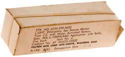
|
Fig 2 The Aluminum tube is to protect the
plastic
light housing from being broken and is supposed
to be in place when deployed.

|
Fig 3 There are loose crystals in the
left end.
There is a small opening that shows up as a light
circle about where the rubber plug is located.

|
Related Marker Lights:
SDU-30
SDU-5/E
A-7 AAF Flashlight Floating
Identification (on One Man Life Raft web page)
Table of Sonobuoys
Naval Consolidated Sonobuoys
@FAS
-
|
Function
|
Start
|
End
|
Links
|
AN/CRT-1
|
5 vacuum tubes single
channel FM transmitter between 67 & 72 Mhz.
See Roswell Connection below where
this was used with "disk microphones" on Project Mogul
CANADIAN
LANCASTER - AN/CRT-1 SONOBUOY SYSTEM - drawing of
aircraft equipment & buoy
Chapter 16 - SOFAR,
HARBOR DEFENSE, AND OTHER SONAR SYSTEMS
Naval History -
RADAR - MAD and CRT-1
CRT-1A: 67.7 to 71.7 MHz
CRT-1B: 62.9 to 66.9 MHz
|
Jun 1942
|
|
|
AN/CRT-4
|
RDRH
Mechanical rotation of hydrophone (Ref 6)
also see SSQ-53 DIFAR patents,
|
Feb 1943
|
|
|
AN/CRT-1A
|
6 channels
|
1944
|
|
|
AN/CRT-1B
|
separate web page (Differences to -1 and
-1A? Let me know)
|
|
|
|
AN/SSQ-1
1951
Ref 6
|
upgraded CRT-4
15 kHz to 17 kHz rotating directional, Magnavox, B-size
(6-7/8" dia x 5' long). 60 lbs.
The US bought the SSQ-20 (UK T-1946) while the bugs
were worked out of the SSQ-1.
|
SSQ-20
until
1954
|
|
|
SSQ-2
1956
Ref
6 |
Magnavox & Bell Labs.
Jerry
Proc SSQ-2B - 4 blade "rotochute"
|
|
15 Feb
1955
|
|
1950
start of: LOFAR Sound Surveillance System (SOSUS, Wiki)
|
SSQ-20
|
|
1951
|
|
|
SSQ-2B
|
Julie explosive
|
1956
|
|
|
AN/SSQ-15
1961
Ref
6 |
Julie RO B-size, Tx 26 kHz
to 38 kHz CW,
|
|
|
|
SSQ-23
1957
Ref
6
|
Julie 100 to 3000 Hz
|
1956
|
19 Nov
1964 |
|
SSQ-28
|
Jezebel-LOFAR
Photos from
John M
|

|
 |
|
1960
|
19 Nov
1964 |
|
SSQ-36
|
BT Moved to the Bathythermographs\SSQ-36
web page.
The BT sonobuoy is an expendable thermal gradient
measurement sonobuoy that operates on one of three or one
of 99 Radio Frequency
(RF) channels. It consists of a thermistor (Wiki)
temperature probe that descends through the bottom of the
sonobuoy canister producing a continuous reading of
temperature versus depth. The thermistor temperature probe
will descend to 1000, 2000, or 2625 feet, depending upon
the sonobuoy selected.
2017 Oct 11 - Navy
places order for 166,500 anti-submarine warfare (ASW)
sonobuoys - many types including -36, -53, -62,
-101, 110, -125, Mk-84
2019 Dec 20 - 600
AN/SSQ-36/53/62 Sonobuoys to Denmark
|
|
|
|
SSQ-38
|
30 day omni-directional
LOFAR
(replaced SSQ-28)
10 to 6,000 Hz
31 chan
|
1964
|
1 June
1961
|
|
SSQ-41
1965
Ref
6
SSQ53A/Ref24&25
|
single hydrophone, Rx:
10-20,000 Hz
replaced both SSQ-23 & SSQ-28
ARR-52 receiver (or ARR-75 with AN/UYS-1, i.e. modern
displays)
Made in large numbers for the Navy.
|
1964
|
|
|
SSQ-47
late 1960s
Ref
6
|
(replaced SSQ-15 Julie
explosive system) Tx (once every 10 seconds): 13 kHz to19
kHz
active ping omni directional range only
replaced by SSQ-50
|
1968
|
|
|
SSQ-48
|
replaced by SSQ-41B
|
|
26 Feb
1981
|
|
SSQ-50
1970s
Ref
6
|
CASS Command Activated
Sonobuoy System, A-size, Pings only on UHF radio command.
Tx: 6.5 to 9.5 kHz.
replace the SSQ-47
in 31 Second Generation Channel frequency plan.
|
|
|
|
SSQ-53
1965
Ref
6
|
31 RF Channels
10 Hz - 2.4 kHz
90 feet fixed depth
|
|
Sep
1967
|
|
SSQ-53A
1979 (YouTube)
|
90 or 1000' depth
1 or 8 hours
YouTube: FixitFrank: SS-Q53A Hydrophone
Sonobuoy Teardown Part 1 - Jun 22, 2021, 2:14:40
|
|
|
|
| SSQ-53B |
DIFAR
fitted with microprocessor
controlled EFS capabilities,
with three depth selections [100, 400 or 1000 feet],
three operating time selections of 1, 3 or 8 hours,
99 vhf channels.
Operation
Before inserting
the launch tube into the aircraft chute the
sonobuoy is programmed for operational life,
channel number and depth by using the SET
button. If done incorrectly pulling the
TEST plug for a few seconds will allow
reprogramming. Power for this comes from a
couple of coin cell batteries. The correct
programming can be confirmed by pressing and
holding the VERIFY button for a couple of
seconds.
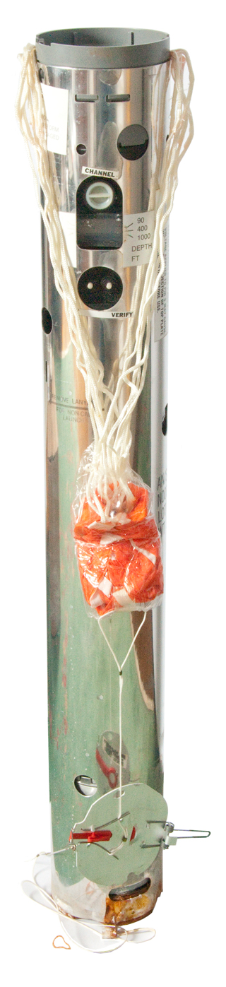
When forced from the aircraft chute by means of
compressed air the lid is blown off the launch
tube deploying the parachute on the metal
sonobuoy housing. The plastic launch tube
stays in the chute.
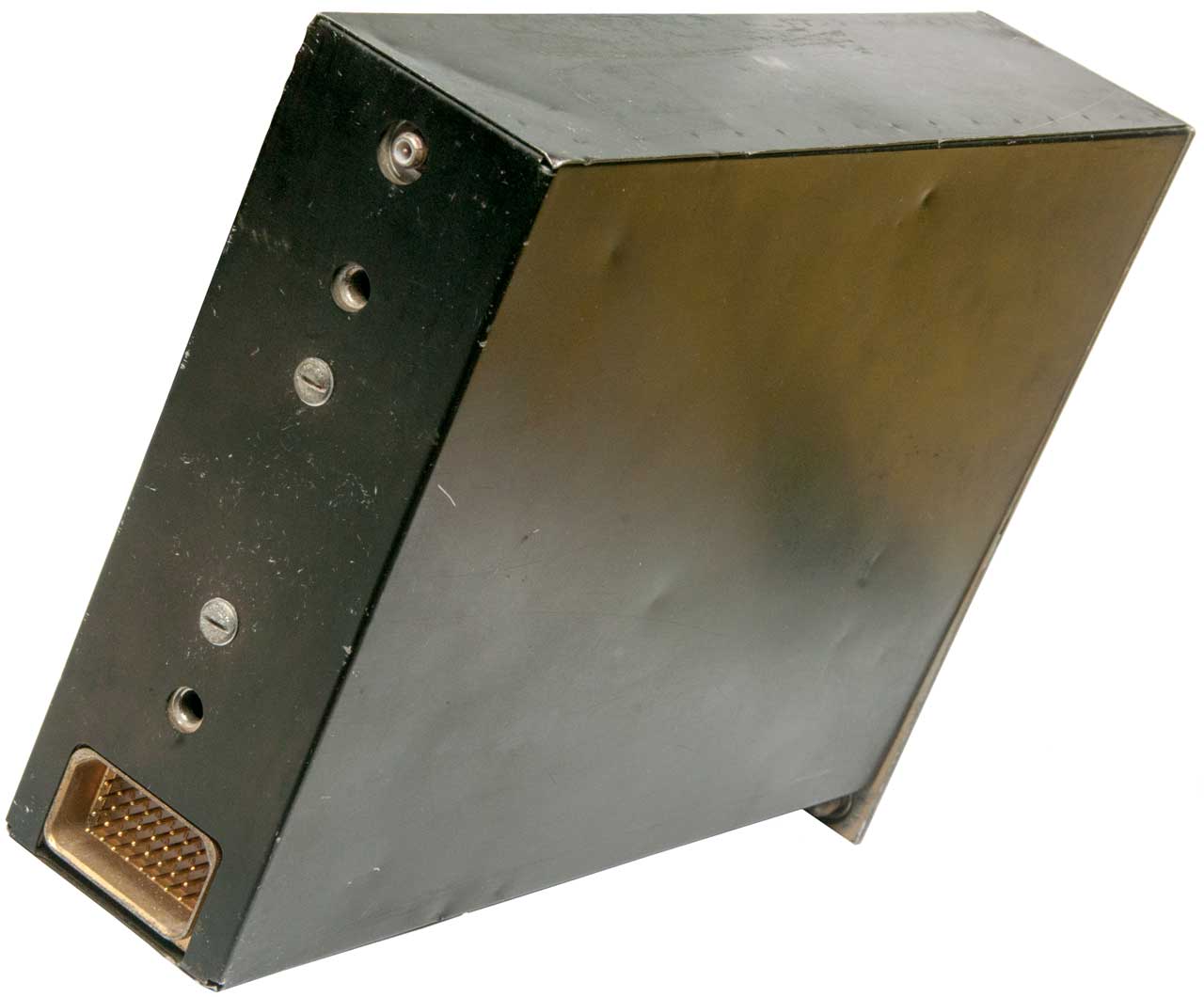
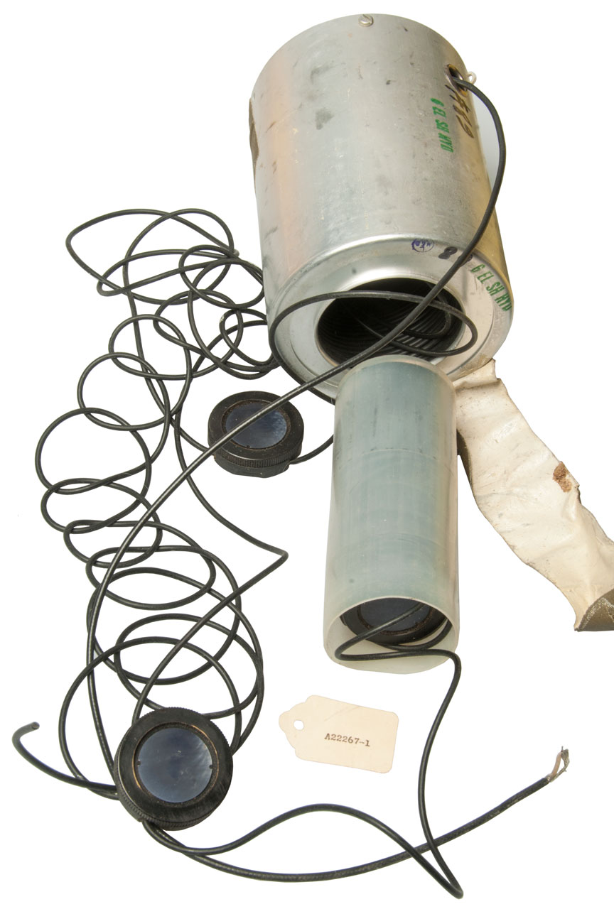
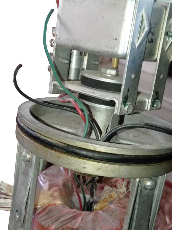
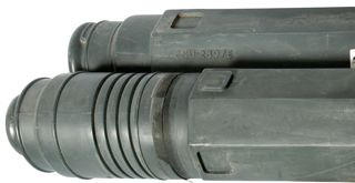
When the metal sonobuoy ( Fig
53-8) impacts the water is starts to
sink and water activates the reserve
battery. As soon as the battery has power
(probably within a few seconds) the squib
retaining the large spring allows an arm to
puncture a compressed gas bottle inflating the
buoy/antenna ( Fig 53-17). At the
same time, depending on the programmed depth one
or both rods ( Fig 53-21) are driven
down to set the amount of cable that will
unspool controlling depth of the sensor. A
very short time later the three main components
of the sonobuoy are separated as the metal outer
housing is blown clear and sinks.
With power the radio transmitter begins to send
it's signal.
The duration may be determined by a simple
electric timer that shuts off the transmitter
after the programmed time, or . . . there
may be some provision to do more?
Although very old I believe this unit would
still work.
|
Fig 53-1

Launch Tube 5-3/8" diz x 39-5/8" long
dated 5/87 - it's 12/11 now so this is just under
25 years old.
The shipping container probably was left on the
ground.
If you know the deployment sequence let me know what it
is. |
Fig
53-2
Top: Channel (01 to 99), Duration (1, 3 or 8 hrs),
Depth (90, 400 or 1000) Ft., Verify
What was a transparent membrane has aged and is
falling apart. When intact would
provide a moisture barrier so the discussant could
keep the inside dry.
|
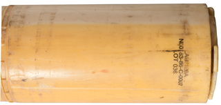
Sonobuoy Launch Container LAU/126A
NOO 83-86-C-0007
.OT 036
|
Fig
53-4
LAU/126A Launch Container Cap

|
Fig
53-5
Cap Off by removing 4 black plastic clips

It's not clear how the sonobuoy was programmed and
in what order loaded into the aircraft launch
chute.
|
Fig
53-6
Inside the Launch Tube, marked:
Caution: - Disengage before launch
Caution: Spring Loaded
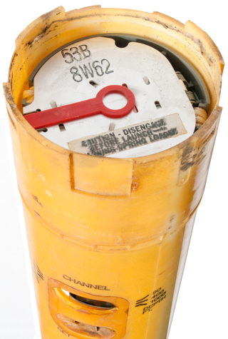
|
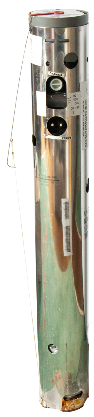
Fig
53-7
SSQ-53B Ready to launch (string holding spring
snare)
The metal SSQ-53B housing is 4-3/4" O.D.
The label just to the right of the depth scale
says:
WARNING Remove Plug Prior to Test
EFS Battery may be damaged if pins 1
and 2 are shorted or voltage is
applied across pins 1 and 2.
Voltage applied to pin 3 may cause high velocity
ejection of top plate.
Reinstall plug before use.
|
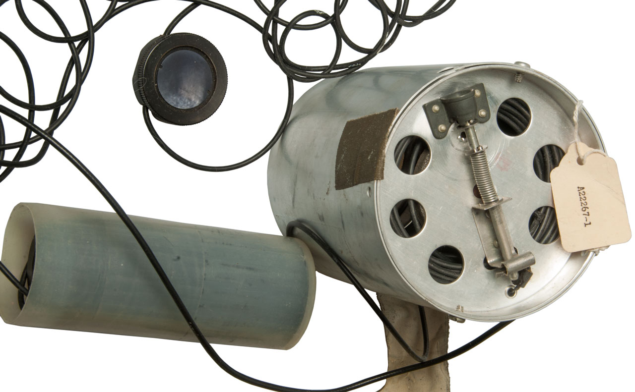
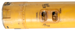
Fig
53-8 With parachute deployed
|
The gray plastic
cap was preyed off instead of submerging in water
and dissolving the two metal links?
|
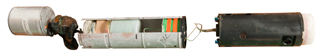
Fig
53-9
There are three functional parts. The right
is the antenna-buoy cover and
receiver/transmitter,
the center is cable spools and the bottom (left)
is the sensor.
|
Fig 53-10
Three Major Components:
Left: Radio, Antenna, Battery
Center: cable
Right: Sensor
|
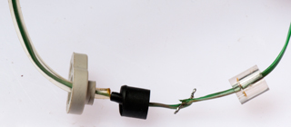
Fig
53-11
Sensor, marked:
Sparton
Corporation
120-0127-002
Clock Number: 0358 Date
06/03/87
{bar code]
SIN: -67.1 db COS: -68.4
db OMNI: -72.1 db
the latter three parameters are related to the
DIFAR aspect of the sensor.
The black cylinder hanging out the bottom is
probably the omni hydrophone.

Note: There's a single green/white wire
(cable) going to/coming from the sensor. I expect
it's a small coax cable, but it remains to be
seen.
|
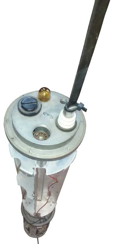
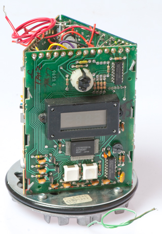
Fig
53-12 Radio Buoy

|
Fig
53-13
With cap pulled off and buoy opened, but not
inflated.
There appears to be small wire antenna with a
resistor at the top.
|
Fig
53-14 Test Socket & Memory Battery
Test Socket cap held by O-Ring, need big pliers to
pull/twist it out.
There was a jumper plug in the socket, more
later.

|
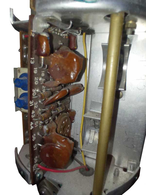
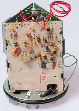
Memory Battery and
PCBs
There's a big spring that can puncture what's
probably a good size CO2 cylinder in
order to inflate the buoy/antenna. There's
what looks like a fusible link holding the spring
in tension that could trigger the gas.
Also at the bottom of the PCB chamber there are a
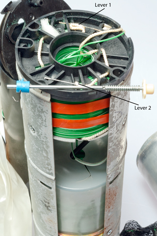
couple of lever arms that have a resistor wrapped
around their ends. If the resistor was
exploded (over powered) then it would release
these arms to do something (maybe control the
depth through the cable spools?
The two coin cells are in the white plastic
holder. They provide about 6 Volts and are
still good.
On the left board there are three red wires
(Battery +), a bare stub where I wiggled off the
battery + wire, and a yellow wire (to socket pin
3). The bare wire at the top (just under the
coin cells) that's soldered to a lug on the
central metal plate is ground (same as the cast
metal frame where the battery- wire connects.).
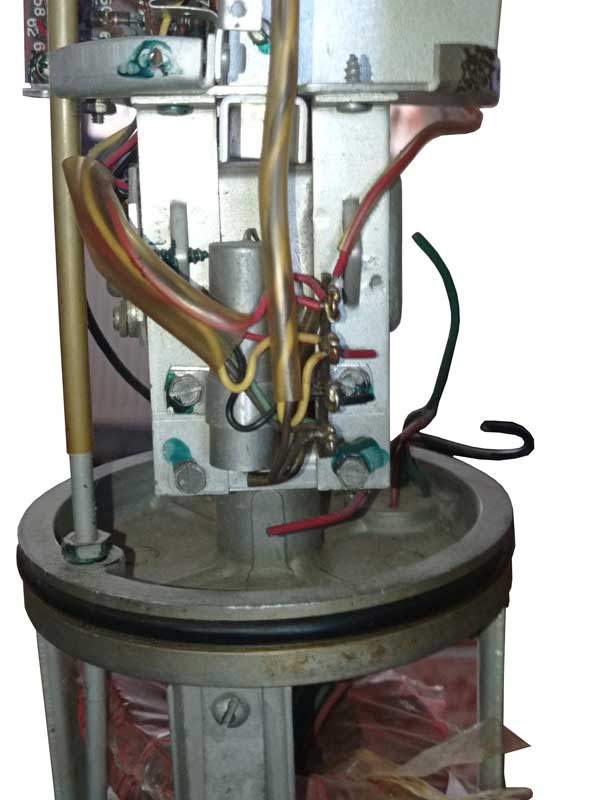
Fig 53-16
|
Battery
Fig 53-17 Main Battery held
to cylinder with double sided foam tape.
1 lb 11 oz. 4-1/4" hi x 3-1/8" w x 2-9/16" d (11 x
8 x 6 cm)
There is a hole on two sides just under the top
cover to allow water to enter.

This is a water activated reserve battery. 1986
Mfg date.
Fig 53-18
In the other photos you can see green deposits on
the inside of the radio/buoy black plastic.
I think that's because this reserve battery
contains Copper in a form that allows it to
escape. This may be a limiting factor for
the shelf life. The Copper deposits are
probably the result of the failure of the moisture
proof membrane that covers the programming push
button switches. Once the moisture in
the air gets to the reserve battery it's going to
become a carrier for the copper and also will
lower the battery capacity.
Idea: Rather than depend on the moisture
proof membrane (and Desiccant (Wiki))
to keep the reserve battery fresh, it should be in
a compartment that's sealed until the metal
housing is separated from the launch tube..
2021 July 29 - That idea will not
work. The battery must allow sea water to
enter the instant the sonobuoy is in the
ocean. It will sink below the surface for
some distance as the battery activates then when
it does activate it will trigger the float.
A better idea might be to use peel off plastic
like is used on Zinc-Air batteries to keep them
fresh. Maybe a way can be found so that
happens when the parachute opens?
The two coin cells are still good condition after
almost 25 years since this was
manufactured.
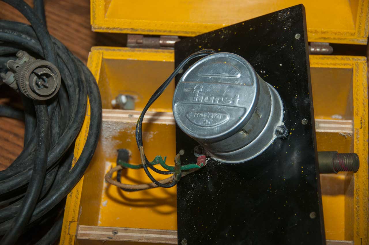
4262069
Lead chloride
battery plate, John
L. Devitt, Douglas
E. Johnson, Robert
S. Willard, Sparton
Corporation, Apr 14, 1981
-
Cites:
3468710
Sea water
battery, Jerome
Goodman, Philip
I Krasnow, Nuclear
Research Associates, Sep
23, 1969 -
Cites:
2692215
Alkaline dry cell, Ruben
Samuel, Oct 19, 1954 -
3005864
Sea water battery, Duncan
T Sharpe, Bell
Telephone Lab, Filed: Mar
29 (16 year delay), 1945, Pub: Oct 24, 1961 -
maybe the Mk 18 torpedo
(Wiki)
|
Fig
53-19 High Pressure Gas bottle to inflate
buoy/antenna
There are three PCBs:
Blue: modulator & RF exciter
Green: I/O panel
Tan: RF Power Amp
|
Fig
53-20 Test Socket Message
Socket Pin
|
Ohms
to Gnd
|
Ohms
to Bat+
|
|
Plug
|
1
|
1M8
|
1M8
|
1-7
|
2
|
876k
|
1M4
|
|
3Note1
|
>1M
|
0.2
|
3-4
|
4
|
0.2
|
405k
|
3-4
|
5
|
1M
|
1M
|
|
6
|
1M |
1M
|
|
7
|
0.1
|
405k
|
1-7
|
Note 1: pin 3 is connected to one side of the
squib that can cut the lanyard holding
the arm that will puncture the high pressure gas
for deploying the buoy/antenna.
Pins 7 & 4 are connected to the ground
bulkhead (0.0 Ohms).
Pin 3 is connected to the red battery wire (0.0
Ohms)
The jumper plug connects:
1 to 7
3 to 4
With the jumper plug removed:
Red test lead to red battery wire (black lead to
ground) = 1M00 Ohms
Black test lead to red battery wire (red lead to
ground) = 401k Ohms
Pin 1 is connected to the negative (black wire)
leading from the two stacked coin cells).
The jumper plug connects pin 1 to pin 7. Pin
7 is connected to the micro controller. So
these two pins relate to zeroing the programming.
If you have information on how the test socket is
used please let me know.
|
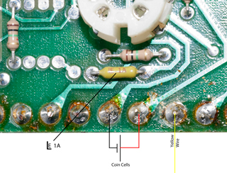
Fig
53-32 Test Socket Schematic
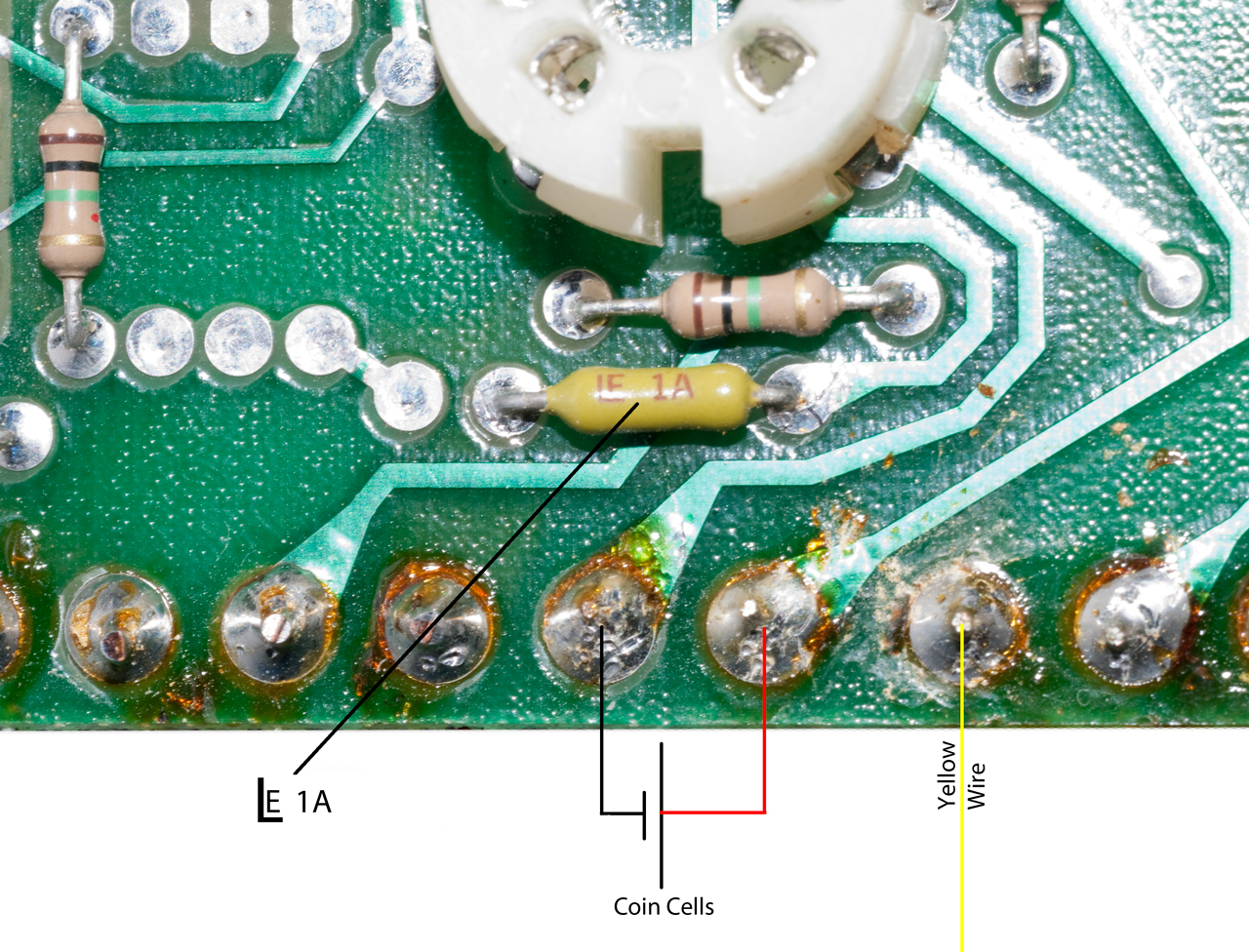
See Fig 55-29 & Fig 53-31 for photo of Fuse
1 (LE 1A)
A few of possible reasons for placing a fuse
directly across the reserve battery. One or
more of them might be the reason. For Now I'll
just remove the fuse.
1) Shorting the main power supply protects the
squibs from being fired by static
or electromagnetic fields (like high
power transmitters on board ships).
2) The reserve battery may activate better with a
heavily loaded. Note: The
BA-4386 Magnesium battery
needs to see a heavy load in order to fully
activate.
3) When the fuse blows the battery is delivering
at least 1 amp and that surge current
would next go to blowing
the squibs. This might be more reliable than
ramping up
the squib voltage.
Pins 5 & 6 each connect to one of the pins on
the micro controller. The Test plug (cable)
probably has a jumper between pins 1 & 7 to
connect the EFS (coin cell) battery thus powering
the micro controller, and when it's powered up the
test socket pins 5 & 6 can be used. But
for what? Data In/Out, firmware programming,
verification check sum, something to do with the
hard wired option jumper to the upper right of the
LCD housing? let me
know. |
Fig 53-21 Buttons (now
working) maybe because of cycling the plug.
Pressing and holding Verify for a couple of
seconds will show the function settings.
To change the settings the plug must be removed
for a few seconds.
Pressing SET starts the channel number counting 0
to 9 to 0.
Pressing SET fixes the tens digit and the units
start counting pressing set fixes the channel
number and the life bars start cycling.
Pressing SET sets the life and then the depth bars
start cycling, pressing SET fixes the depth.
Now pressing Verify for a few seconds will display
the function settings.
They were set for: 1 hr, chan 63 & 1000'
Now set for 3 hrs, chan 54 and 400'.
|
Fig
53-22 EFS LCD (plug shown installed)

|
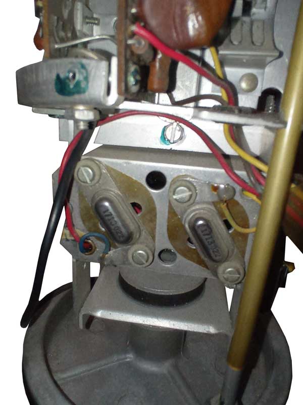
Fig
53-23 Depth Selection
The two levers are either in the position shown or
they are pushed toward the center
to select how much cable is deployed. The
selection is made by the two blue plastic
actuators using a push (or pull) of the rod with
the spring. Note this rod is smooth and
would not support a rotary motion. Also the
two levers in the bottom of the radio compartment
work in an up or down fashion, not in a rotary
fashion. See Fig 53-9 and
a close up from it Fig 53-22 below..
|
Fig
53-24 Close up photo of depth selection blue
plastic parts.
|
Fig
53-25 Cutting Squib Wires
Three red wires have been cut deactivating the
three squibs so DC power can be applied.
|
Test Socket
Resistance readings after cutting the wires:
Pin
|
Ohm
to Gnd
|
Ohms
to Bat +
|
|
Plug
|
1
|
1M9
|
OL
|
1-7 |
2
|
860K
|
OL
|
|
3
|
>1M
|
1.9 |
3-4
|
4
|
0.6
|
>1M |
3-4 |
5
|
1M0
|
1M3
|
|
6
|
1M0 |
1M6 |
|
7
|
0.5
|
1.9 |
1-7 |
Gnd to Batt+ (w/0 Plug) = 1M0
Gnd to Batt+ (w Plug) = 0.7
There is still a dead short across the
battery terminals!
pin3 is yellow wire to Battery + terminal (and red
wires)
pin 4 is the metal frame (battery -) the black
battery wire with the internal tooth lug.
This is confusing.
The hi pres gas squib is 36.2 Ohms.
One of the depth squibs is 18.5 Ohms (red to
violet) not to ground.
The other depth squib is 18.3 Ohms (red to blue)
not to ground.
These may be 1/8 Watt 18 Ohm resistors. Rated
power would be at 1.5 Volts, 10X power at 4.7V,
100X power at 15 Volts, so if the battery is about
15 volts the resistors would fail mechanically.
Note the plug must be installed for the
programming to work, so operation without the plug
is not an option. The plug has a
jumper between pins 3 and 4 that is part of the
path shorting the battery + and - terminals.
The coax feeding the antenna reads 42.7
Ohms.(resistor is Yel-Org-Blk-Red)
|
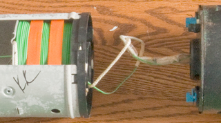
Fig
53-26 Green Cable
10K0 Ohms either polarity.
This joint is located on the black plastic bottom
plate of the Transmitter section.
White to White, Green to Green.
See: Fig 53-10 and Fig 53-12.
|
How to take apart
the transmitter? It may be possible to push
everything out the bottom, but that would break
the two push button switches. Probably the
best way is to saw from top to bottom at two
places 180 degrees apart.
|
Fig
53-27
The switch buttons are mechanical working through
a rubber boot and can be pulled
out of the plastic housing.

After letting the top sit overnight after applying
some Kroil to the joint between the plastic
housing and the metal plate with O-ring seal the
assembly pressed out the bottom easily. It
was necessary to un-solder the antenna cable and
the green wire to isolate the top section.
|
Fig
53-28 RF Amplifier
Tan PCB from top section
The antenna was connected at the top of this board
where the notch is.
Gnd to the left and center to the right of the
notch.
This is probably the Tx power amplifier and
antenna matching/filtering board.
|
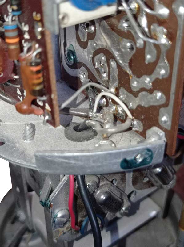
Fig
53-29 Command and Control Board
Green PCB from top section.
This is the digital board.
I doubt the micro controller is doing anything
with the sensor data, so it's
probably running at a very slow clock frequency to
conserve power.
So there's no need for a crystal for it.
There are three 2N6724 2 Watt NPN Darlington
transistors just to the left of the push buttons
used for firing the three squibs. The
collectors go to the squibs and all three emitters
are connected to the bulkhead ground plate.
Top: RF Amp board depth squib
Center: Synth board depth squib
Bottom: CO2
Maybe the transistor that blows the antenna squib
is on the RF amp board? or maybe it's just the
battery?
Above the upper right corner of the black plastic
LCD housing there is a row of 6 holes and a jumper
is installed in the right most of
these.
What option is this selecting? Let me know.
|
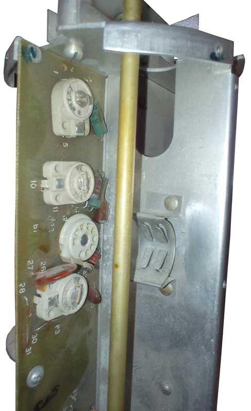
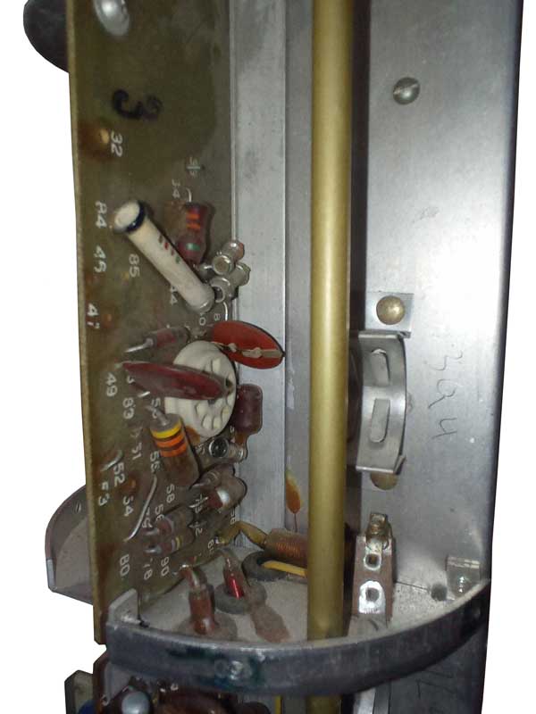
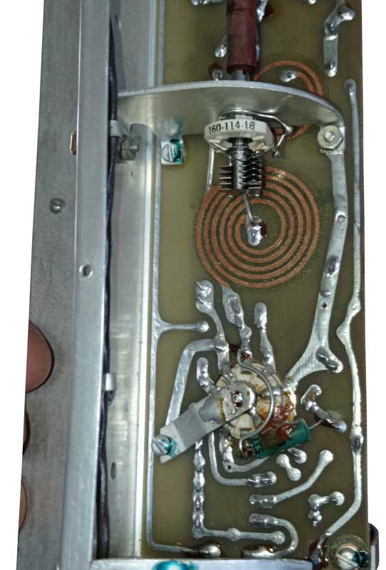
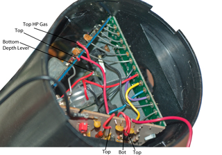
Fig
53-30 Synthesizer and Modulator Board
Blue PCB from top section.
This board interfaces with the sensor package.
The crystal at the lower left is marked:
10.2985 MHz. This is a non standard value,
see my Crystals web
page.
Maybe related to the DIFAR spectrum.
This board seems to be mostly analog in nature.

On the bulkhead plate at the bottom there are the
two depth programming levers.
As shown the squibs (resistors) are intact and the
lever is held in the down position.
The two rods are spring loaded and trying to lift
up. When the squibs are broken
the depth programming rods are forced up by their
spring.
At the bottom right the green/white sensor cable
can bee seen coming through a hole
and its connection to two pads.
All three squibs measure 500K Ohms to Bat+ and
open to Ground. So they are not causing the
dead battery short.
The date codes on the ICs are 1984, 1985 &
1987.
|
6 Jan 2012 - New Idea about the direct
battery short.
The short may be
part of a Safe And Arm system that would prevent
the buoy
from becoming active prior to an actual
launch. This may be a common system
used not only on sonobuoys but also things like
countermeasures equipment like
flares and chaff
dispensers.
If that's the case then something about the
pneumatic launch would disable the short.
|
Fig
53-31 Fuse on digital PCB
This appears to be the cause of the dead short
across the reserve battery terminals.
|
Power Up (with
sensor disconnected, antenna attached)
For about 15 seconds the current is in the 30 ma
range then jumps up to150 to 200 ma when the
transmitter turns on.
After battery power the Verify button does not
work.
The battery voltage appears on the green/white
cable.
|
On reconnecting the
green cable between the floating buoy and the
sensor.
Buoy
The resistance between the two wires and ground
is: left: 1M and right 10k.
The resistance between the two wires and
Batt+ is: left: 0.2 and right 1M
Sensor
The resistance between either wire and the sensor
metal is an open circuit.
So as of 12 Jan 2012 it's still not clear how to
be sure the polarity is correct to reconnect the
sensor.
|
Thanks to Ugo in
Italy there are two conductors in the cable, one
supplies power to the sensor package (which has
input filter caps) and the other is the audio
signal to be modulated onto the transmitter.
Seawater forms a ground return between the
floating transmitter and the sensor. This is
confirmed by the book The Ears of
Air ASW. pg 241 (Ref 2)
|
|
|
1984
|
|
| SSQ-53D |
Dwarf "G" size version of
the B
|
1991
|
|
|
| SSQ-53D |
DIFAR only sensor, 90, 400
or 1000 feet, no CFS
-53D(2)
5 Hz - 2.4 kHz
1/2, 1, 2, 4 or 8 hours
-53D(3)
sea state 6
----------------
Ref 32: The
AN/SSQ-53D DIFAR sonobuoy incorporates the Electronic
Function Select (EFS) capability which provides the
operator with the capability of electronically selecting
one of the available 99 RF channels, sonobuoy life of
one-half, one, two, four, or eight hours, and hydrophone
depth of 90, 400, or 1000 feet. The AN/SSQ-53D also has
improved suspension, wider sonic response curve, and
electronic upgrades compared to previous DIFAR sonobuoys.
|
2003
|
|
|
| SSQ-53E |
Digital version
Additional hydrophone @ 45' for CSO
CFS
100, 200, 400 or 1000 feet
AGC
91.44 cm long
-----------------------
Ref 32: The
AN/SSQ-53E DIFAR sonobuoy incorporates Command Function
Select (CFS). Through CFS, a suitably equipped ASW
aircraft can transmit Ultra High Frequency (UHF) radio
commands to the sonobuoy. These commands select Very High
Frequency (VHF) operation (on/off), hydrophone reception
(Constant Shallow Omni (CSO)/Normal, Automatic Gain
Control (AGC) operation (on/off), and change RF channel
frequency. The CSO is an omnidirectional hydrophone
positioned at a depth setting of 45 feet. It is less
sensitive than the normal DIFAR hydrophone, but is useful
against an evasive submarine. AGC selection provides the
operator additional flexibility when operating in a noisy
environment. The ability to select VHF operation and
change RF channels enhances operations in the littoral
environment. Also, the AN/SSQ-53E includes an additional
200 feet EFS depth setting. |
|
|
|
SSQ-53F
|
DIFAR,
CSO
made by combining the
305 cm long
SSQ-53E & SSQ-57
NSN 5845-01-475-9870
adds CO hydrophone with directional units (replaces
SSQ-57)
CFS Rx - single channel UHF
Tx - 96 selectable frequencies (136 - 173.5 MHz), 1W
90, 200, 400, 1000 Ft.
"In order to process the DIFAR 53F, a demodulator strips
the NEMA GPS stream off a 30 kHz carrier on each audio
channels before transmitting it through a 232 serial
interface to the STB (SDR System Test Bed), which has a
component that reads this serial stream and parses the
associated NEMA GPS messages for use by the system." TM2011-140_i.pdf
|
2000
|
|
|
SSQ-57A
1970s
Ref
6
|
Calibrated-LOFAR
-57 Rx: 10 to 10,000 Hz, -57A Rx: 10 to 20,000 Hz.
See separate web page
|
1972
|
|
|
SSQ-57B
|
Ref
32: The LOFAR sonobuoy is an expendable,
omnidirectional passive sonar unit. It consists of an
omnidirectional hydrophone that descends through the
bottom of the sonobuoy canister to a pre-selected depth.
The LOFAR operates from one of 31 RF channels preset
during manufacturing. There is a selectable operating life
of one, three, or eight hours and selectable operating
depth of 90 or 400 feet. |
|
|
|
SSQ-62
late 1970s
Ref
6
|
DICASS
Directional Command Activated Sonobuoy System
FM sweeps (FM-CW allows determining range (Wiki)
a 4-hour life and 50 seconds of ping time, provides an
instant range and bearing to the contact for each command
and active ping.
99 channel Third
generation frequency plan.
|
1976
|
|
|
| SSQ-62B |
Ref
32: The AN/SSQ-62B DICASS may be command activated
to change depth, to activate sonar transmissions and to
scuttle the sonobuoy. The AN/SSQ-62B DICASS operates on
one of four preset sonar channels and one of 31 preset RF
channels. These channels are preset by the manufacturer
and cannot be changed. Upon deployment, the AN/SSQ-62B
DICASS will initially deploy to a depth of 90 feet. Upon
receipt of a command signal, the transducer will deploy to
a depth of 400 or 1500 feet. |
|
|
|
SSQ-62C
|
Ref 32: The AN/SSQ-62C DICASS also
operates on one of 86 preset sonar channels. The channels
are preset prior to flight to one of 86 preset RF channels
that correspond with the preset sonar channel. Upon
deployment, the AN/SSQ-62C DICASS will initially deploy to
a depth of 90 feet. Upon receipt of a command signal, the
transducer will deploy to a depth of 400 feet or 1500/2500
feet. The 1500 or 2500 foot depth option must be selected
through the EFS during preflight. |
1993
|
|
|
| SSQ-62D |
Ref
32: The AN/SSQ-62D DICASS has been improved with the
replacement of the lithium chemistry battery with a
thermal battery. Additionally, the sonobuoy includes the
EFS option of selectable depth families. During preflight,
either a shallow or deep family of depth option shall be
selected. If the shallow family is selected, depth
settings of 50, 150, or 300 feet are available. If the
deep family is selected, depth settings of 90, 400, and
1500 are available. These depth options provide sufficient
flexibility for both littoral and open ocean ASW
operations. |
|
|
|
SSQ-62E
|
Command Function Select
Electronic Function Select
96 chan 136.000 - 173.500 MHz
CW Out: 6.5, 7.5, 8.5 or 9.5 kHz
--------------------------
Ref 32: The
AN/SSQ-62E DICASS includes the following improvements and
modifications to the AN/SSQ-62D DICASS design. It
incorporates CFS, allowing a suitably equipped ASW
aircraft to transmit UHF radio commands to the sonobuoy.
These commands select VHF operation (on/off), change RF
channel frequency and associated sonar channel frequency,
change sonar frequency independently, and change depth
setting. These features all provide enhancements for both
deep water and littoral ASW environments. Additionally,
the AN/SSQ-62E DICASS will include all four available
sonar channel frequencies into a single sonobuoy which
provides significant logistics savings. |
|
|
Sonobuoy Tech
Systems
|
SSQ-77
1970s
Ref 6 |
VLAD |
|
|
|
SSQ-77A
1981
Ref
6
|
VLAD
(Vertical Line Array DIFAR) |
1981
|
|
|
| SSQ-77B |
" more hydrophones, 2
depths, 2 beams
Ref 32: The
VLAD sonobuoy is an expendable, omnidirectional passive
sonar unit. The VLAD uses a multi-element omnidirectional
hydrophone array and a beamforming filter assembly to
enhance acoustic sensitivity. The VLAD has a selectable
configuration incorporated into the EFS. This allows the
operator to select either bottom bounce or convergence
zone sound reception. The EFS will also allow selection of
one of 99 RF channels, two operating depths of 500 and
1000 feet, and selectable life settings of one, four, or
eight hours. In all other respects, the VLAD is comparable
to the DIFAR. |
1989
|
|
|
SSQ-77C
|
" adds RF command function
selection |
|
|
|
SSQ-86
|
DLC
Ref 32: The
DLC sonobuoy is an expendable, acoustic communication
device designed to transmit a preprogrammed message to a
submerged submarine. It consists of an omnidirectional
acoustic transducer that descends through the bottom of
the sonobuoy canister to a shallow transmission depth of
75 feet. After completing shallow depth transmissions, the
transducer automatically descends to the deep transmission
depth of 350 feet. The messages are encoded through the
EFS prior to launch. The acoustic transmission frequencies
are classified. The message transmission includes an
address group, an addressee group, and two word groups.
The sonobuoy does not have an RF transmitter. |
|
|
|
SSQ-101
early 1990s
Ref
6
Ref 49
|
ADAR
Advanced Deployable Acoustic Receiver SSQ-101 NSN:
5845-01-453-8699
Ref 32: The
ADAR sonobuoy is an expendable unit capable of receiving
UHF downlink commands and sending real-time beamformed
acoustic data via a VHF digital uplink to the monitoring
unit. The ADAR will be a free-floating acoustic data
receiver that will operate in conjunction with an acoustic
source. The buoy will also scuttle automatically upon
detection of a low voltage state or completion of its six
hour life. |
FY97
|
|
|
SSQ-101B
Q101B.pdf
|
NSN: 5845-01-629-8534
|
|
|
|
| SSQ-110 |
Ref
32: The AN/SSQ-110 EER sonobuoy operates on one of
31 selectable RF channels and is composed of two sections.
The upper section is called the control buoy and is
similar to the upper electronics package of the AN/SSQ-62
DICASS sonobuoy. The lower section consists of two
explosive payloads of Class A explosive weighing 4.2
pounds each. The arming and firing mechanism is
hydrostatically armed and detonated. |
|
|
|
SSQ-110A
|
EER
MIL-S-29593, 30 July 1997
Ref 32: The
EER sonobuoy is an expendable sonobuoy that is a
commandable, air-dropped, high source level acoustic
source.
The SSQ-110A EER includes the following improvements and
modifications to the AN/SSQ-110 EER design. The
AN/SSQ-110A EER includes the EFS feature. EFS allows the
selection of one of 99 RF channels. Additionally, the
sonobuoy adds a classified depth setting for a total
number of two depth settings. Upon deployment, the
AN/SSQ-110A EER can be sent to its deeper depth setting
via UHF radio commands. |
|
30 July
1997
|
|
SSQ-120
|
(Wiki)
Transportable Radio Direction-Finding system, ...has HF,
VHF, and UHF antennas and direction-finding logic. FBOdaily
March 22, 1999
|
|
|
|
SSQ-125
|
advanced EER ADLFP sound
source
used with: ADAR sonobuoys like SSQ-53F, SSQ-77C and
SSQ-101 |
|
|
|
SSQ-536
|
BT |
|
|
|
SSQ-801
|
BARRA |
|
|
|
SSQ-906
|
LOFAR Omni
|
|
|
|
SSQ-926
|
ALFEA, GPS
5452262
Radio telemetry buoy for long-range communication, James
D. Hagerty, Navy,
1995-09-19, - 3 to 6 MHz Rx/Tx, GPS Rx, 162 to 173 Tx.
|
|
|
|
SSQ-937C
|
BT |
|
|
|
SSQ-954
|
DIFAR |
|
|
|
SSQ-955
|
HIDAR |
|
|
|
SSQ-963D
|
CAMBS |
|
|
Janes
|
SSQ-981
|
BARRA |
|
|
|
Sonobuoy Aircraft Systems
Receivers
R-2/ARR-3 see the CRT-1 Sonobuoy page.
CIA-46186 (RBF-1)
ARR-52 sonobuoy Aircraft Receiver
The ARR-52 was a 16 channel receiver and the ARR-52A is a 32
channel receiver. (See: RxControl: ARR52A)
R-1170/ARR-52A
The internal modules have markings like:
Module 1
|
p/o R1170/ARR-52A |
16 Tuning caps for crystal oscillators
|
Module 2
|
R-962 A/ARR-52
|
|
| Module3 |
R-962 A/ARR-52 |
|
| Module4 |
R-962 A/ARR-52 |
|
| Module5 |
R-962 A/ARR-52 |
|
This suggests the ARR-52 (no letter) was made up of modules which
were all marked R-962 A/ARR-52.
The R-962/ARR-52 has
NSN:
5845-00-835-6218 and is 11.687x7.437x2.187", runs on 18 VDC,
16 channels (?) between 162.0 - 174.0, F9
The R-1170/ARR-52A has NSN
5845-00-999-6284
(4 March 1966)
Fig 1 Front Test Points: AGC, Disc &
AFC.
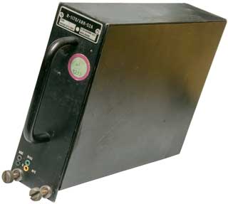
|
Fig 2 Back antenna and system connectors.
 |
Fig 3 Inside Top View
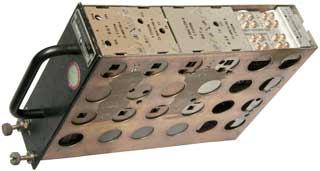 |
Fig 4 Inside Bottom View
 |
Fig 5 Module 1 has 16 crystals on each side
(32 total)
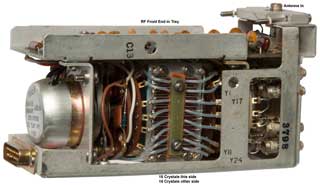 |
Fig 6 Module 2 Function???? (blank back
side)
 |
Fig 7 Module 3 Guess 5 MHz second IF (blank
back side)
 |
Fig 8 Module 4 Guess 26 MHz first IF
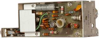 |
Fig 9 Module 4 Guess 26 MHz first IF
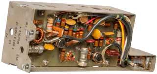 |
Fig 10 Module 5 Guess power supply &
audio amp
DE-9P-C7 on DB-15 connector
 |
Fig 11 Module 5 Guess power supply &
audio amp
 |
Fig 12 Chassis with 26 Mhz filter between
Module 1 and Module 4.
5 MHz filter between Module 4 (cap to Module 1) and Module
3.
 |
Fig 13 Module
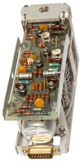 |
|
|
CQ magazine October 1974, Conversion to 2 meters?
Some info from Radio
Nerds:
ARR-52,A	R-962/1170 Sonobuoy Receiver  162.5-173.5 MC  AM-FM-Video
 AM-2375,76/	ARR-52 RF Amps.
 ARM-53		ARR-52 Test Set
 AT-933/	ARR-52 Antenna (2 used)
 C-3109,10*/	R-962/ Control Boxes, 4 & 2 Signal Channels, 16 RF Channels
 C-4505,06*/	R-1170/ Control Boxes, 4 & 2 Signal Channels, 31 RF Channels NSN: 5845-00-999-6285
 C-4506         NSN: 5845-00-999-6286
 MT-2258/	ARR-52 4-Receiver Rack Case
 MT-2259/	ARR-52 Shockmount for MT-2258/
 PP-2479/	ARR-52 PS 115 VAC & 28 VDC in, -6, +18, +135 VDC out
 RD-53/ARH	ARR-52 Bathythermograph Recorder  U/W AM-1569/ARR-26 & IP-347/
 SB-1084,85/	Signal Level Meters, 4 & 2 Channels
ARR-52 Patents
Channel select rotary solenoid - about 1-18" diameter.
2496880
Magnetically operated device,
George
H Leland, 1950-02-07, - first application was for air
dropped bomb fuzes - "
Ledex" is the
brand name, Channel select rotary solenoid
2501950
Commutating switch mechanism, George H Leland, 1950-03-28, -
Channel select rotary solenoid
2790153
Polarized electrical plug and socket connector having a plurality
of contacts, Samuel L Arson, Cannon Electric Co, 1957-04-23- the
original DB connector series? the prior patents used a rectangular
array of contacts and something other than the contacts to prevent
installing 180 degrees from the correct orientation, such as male
and female threads on the screws.
General Sonobuoy Receiver Patents
3778728
Phaselocked-fm detector apparatus, R Nupp,
EDMAC
ASS, 1973-12-11, -
3845402
Sonobuoy receiver system, floating coupler, R Nupp,
EDMAC
ASS, 1974-10-29, -
ARR-75
 |
ASA-20 Control
Drift - Compute - Reset
PDI (Pulse Doppler Indicator): BDHI (Bearing Distance
Heading Indicator): Marker 1 to 6, GTP: Marker 1 to
6 Insert
ASA-20 or
AQA-1
ASA-20 or AQA-1
A-B: 1 to 6
Computer
Ellipse
A: Off to
6
Data
Release
B: Off to 6
|
ASA-31 Julie Control
Panel

|
Julie Control
|
ASA-20 Sonobuoy Recorder "Jezebel".
The AQA-5 is a 4 channel paper chart recorder.
Youtube video:
AN/AQA-5 Acoustic Charts
Recorder
1:16 - monitors 4 sonobuoys in parallel
P-3 Orion Aircraft -
Walk Around
-
BDHI: Bearing Distance Heading Indicator
PDI: Pulse Doppler Illuminator
3582871
Ellipictal Computer System, Morris Snyder (Navy), Jun 1, 1971,
367/3; 367/107; 701/300; 708/801 - determines sub position using
sonobuoys
AN/ARR-502 Multichannel Sonobuoy Receiver (
data
sheet,
data
sheet)
AQA-7(V)1/2 Directional
Acoustic-Frequency Analysis and Recording System (DIFAR)
ASQ-114 digital computer has a memory loaded with a large number
of sound profiles of submarines and radar- and radio signals for
comparing ESM measurements
Forward Looking Infra Red (FLIR) replaced the Low Light Level
TeleVision system (LLLTV)
ASR-3 Sonobuoy Reference System (SRS) - used multiple antennas to
determine bearing to sonobuoy
Digital magnetic Tape System (DMTS) -
Integrated Acoustic Communication System (IACS) - sub coms
Litton LTN-72 navigation system used with the INS and Doppler
navigation systems
ALR-66 (
Wiki)
ESM systems (
Wiki)
using the Adaptive Controlled Phased Array System (ACPA) (ESM is
closely related to
RWR)
Deinterleaver
Technology for Future ESM systems, Dec 1992 NSWC - each
pulse received from a single emitter can be agile in frequency,
pulse width, pulse amplitude, pulse repetition interval, but not
direction. So using the Pulse Descriptor Word from the ESM
sensor a future deinterleaver can sort out each emitter and
differentiate between friendly and hostile emitters. ESM
systems mentioned:
Racal SADIE
IBM Associative Comparator
Anaren ESM Processor
ALQ-32 Inner Processor
Instantaneous Frequency Measurement
(IFM) receivers are part of the ESM sensor. But this
type of receiver can have problems with two signals at the same
time or with a CW signal anywhere in it's frequency range. The
proposed configuration is to use narrow band receivers (many
channels) and for each channel two paths, one for angle of
arrival and the other for characterization of the received
signal.
Outdoor Intrusion Detectors based on Sonobuoy
Technology
15 April 2023: The AN/TSQ-108(*) Radar Sonar Surveillance
Center "van's" are basically a P-3 Orion without wings or
torpedoes..( FAS, USNI)
SRQ-17 (Wiki, Ref 48)
Link between Vietnam Intrusion
Detectors and Navy
6 Sep 2019 Discovered the next 3 patents while looking for
information on the RR-97/AL chaff
brick. The inventors of Navy Sonobuoy containers also
invented seismic and acoustic intrusion detectors. This is
the link that was obvious 7 years ago in 2012, but now is
confirmed.

|
3891865
Intrusion detector, Salvatore
R Picard, Robert
F Starry, US Navy, 1975-06-24, 327/37;
340/539.1; 340/522; 340/566; 340/539.14 - "A
low-current detection device responsive to both audio and
seismic input signals received over predetermined periods
of time at preselected amplitude levels."
Seismic & Audio inputs. Optional night
operation. 3 tones (United Aircraft H2102 tone
generator) in the range of 19 kHz to 32 kHz depending on
code select plug.
|
Citations
Publication
number Priority date Publication date
Assignee Title
US3139539A *1962-03-30
1964-06-30 Gen Electric Control circuit
producing output signal so long as input pulses occur within
certain time interval
US3517316A *1966-03-22
1970-06-23 Res Instr & Controls Inc
Surveillance equipment and system
US3552520A *1968-02-27
1971-01-05 Us Navy Detecting and transmitting
system with interval timing means
US3569923A *1967-10-30
1971-03-09 Us Navy Adaptive acoustic detector
apparatus
US3585581A *1969-07-22
1971-06-15 Honeywell Inc Seismic sensor
apparatus
US3613061A *1968-08-29
1971-10-12 Bryant D Lund Pressure-responsive,
timed, electronic control apparatus and method
US3691549A *1970-12-02
1972-09-12 Sylvania Electric Prod Signal
processor
US3714622A *1969-12-12
1973-01-30 Us Navy Adaptive agc system
Cited by
Publication
number Priority date Publication date
Assignee Title
US4604738A *1982-02-22
1986-08-05 Honeywell Inc. Method and
apparatus for classification of a moving terrestrial
vehicle as light or heavy, compensates for different
distances from vehicle to sensor by comparing the energy
in the acoustic and seismic signals.
Citations
Publication
number Priority date Publication
date Assignee Title
US3585581A *1969-07-22
1971-06-15 Honeywell Inc Seismic
sensor apparatus
US3824532A *1971-09-27
1974-07-16 Us Air Force Seismic signal
intrusion detection classification system
US3891865A *1973-11-14
1975-06-24 Us Navy Intrusion detector
US3903512A *1974-03-07
1975-09-02 GTE Sylvania Inc Signal
processor
US3984804A *1971-11-29
1976-10-05 Navy Acoustic and seismic
troop movement detector
US3995223A *1970-02-19
1976-11-30 Navy Seismic-acoustic
detection device
US4081785A *1974-02-13
1978-03-28 Air Force Dual class
amphibious target discriminator
US4090180A *1976-03-16
1978-05-16 Elliott Brothers (London)
Limited Vibration-responsive intruder alarm
system
US4158832A *1961-06-19
1979-06-19 Army Seismic apparatus for
discrimination between track-type vehicles and
wheel-type vehicles
US4271491A *1978-11-20
1981-06-02 Simpson Ronald R Intruder
alarm system
US4337528A *1972-12-13
1982-06-29 Air Force Moving vehicle
seismic target detector
Cited by
Publication
number Priority date Publication
date Assignee Title
US4953144A *1989-09-11
1990-08-28 Shell Oil Company
Third-party detection around pipelines
US5007032A *1990-06-08
1991-04-09 Honeywell Inc. Acoustic
alert sensor
EP0535570A1 *1991-10-01
1993-04-07 Rockwell International
Corporation Transient detection
processing, especially underwater acoustic
signal recognition
US5229765A *1991-05-08
1993-07-20 Halliburton Logging Services,
Inc. SP noise cancellation technique
US5737433A *1996-01-16
1998-04-07 Gardner; William A.
Sound environment control apparatus
US6385130B1 *2000-09-11
2002-05-07 Navy Dual channel
switch with frequency band limiting
EP1222445A1 *1999-10-06
2002-07-17 George W. Herndon
Seismic weigh-in-motion system
DE4212072C2 *1992-04-10
2002-09-26 Stn Atlas Elektronik
Gmbh A method of detecting and
classifying sound sources, in particular of
vehicles
WO2005034062A1 *2003-10-02
2005-04-14 Robert Bosch Gmbh
Method for the evaluation and temporal
stabilization of classification results
US20070062289A1 *2005-09-07
2007-03-22 Luna Innovations
Incorporated Method and apparatus for
acoustically weighing moving loads
EP1835308A12006-03-16
2007-09-19 SmartTrig AB Detection
unit and a method of using the same
WO2009019706A2 *2007-08-09
2009-02-12 Elta Systems Ltd Method
and apparatus for detecting pedestrians
US20100157729A1 *2008-12-19
2010-06-24 Bae Systems Information And
Electronic Systems Integration Inc.
Seismic Method For Vehicle Detection And
Vehicle Weight Classification
US20110199861A1 *2007-03-12
2011-08-18 Elta Systems Ltd.
Method and system for detecting motorized
objects
US8331195B1 *2008-10-20
2012-12-11 Army Computer
implemented sensor data analysis
US20150168545A1 *2013-12-13
2015-06-18 Agency For Defense
Development Distance estimation device
and method using the difference of wave speed
between waves
US8331195B1 *2008-10-20
2012-12-11 Army Computer implemented sensor
data analysis - Igloo White (
Wiki)

|
3995223
Seismic-acoustic detection device, George
A. Gimber, Edward
J. Cotilla, Salvatore
R. Picard, Robert
F. Starry, US Navy, Priority: 1970-02-19, Pub:
1976-11-3, 327/25; 367/93; 181/122 -
"an acoustic sensor, a seismic sensor and an acoustic
signal transmitter." Inventors are with Navy and have
sonobuoy related patents.
The illustrations in this patent are almost identical to
patent 5054006 below.
|
Citations
Publication
number Priority date Publication date
Assignee Title
US3543172A *1968-09-19
1970-11-24 Anderson Jacobson Inc Digital
frequency discriminator
US3641443A *1969-12-11
1972-02-08 Westinghouse Electric Corp Frequency
compensated pulse time discriminator
US3705417A *1971-12-16
1972-12-05 Tel Tone Corp Pulse ratio detector
Cited by
Publication
number Priority date Publication date
Assignee Title
US4107616A *1976-01-22
1978-08-15 M. L. Engineering (Plymouth) Limited
Signal monitoring circuit
US4230992A *1979-05-04
1980-10-28 Minnesota Mining And Manufacturing
Company Remote control system for traffic signal
control system
FR2521307A1 *1982-02-11
1983-08-12 Krupp Gmbh Passive method for
acquiring data relating to a target that is a mobile
preferably acoustic source
DE3306155A1 *1982-02-22
1983-09-01 Honeywell Inc Device for
weight-dependent classification of vehicles
FR2592200A1 *1985-12-24
1987-06-26 Maisonnette Miche lElectronic device
for detecting any untimely triggering of an alarm
US4811308A *1986-10-29
1989-03-07 Michel Howard E Seismo-acoustic
detection, identification, and tracking of stealth aircraft
US5007032A *1990-06-08
1991-04-09 Honeywell Inc. Acoustic alert sensor
WO1991006874A1 *1989-11-02
1991-05-16 Rheinmetall Gmbh Process for
determining the direction and range of noise-generating
targets
US5054006A *1970-02-19
1991-10-01 The United States Of America As Represented
By The Secretary Of The Navy Seismic-acoustic
detection device
WO1997019368A1 *1995-11-17
1997-05-29 Stn Atlas Elektronik Gmbh Method and
device for detecting pedestrians
ES2170603A1 *1998-06-19
2002-08-01 Tzn Forschung & Entwicklung
Surface mine defense
US8331195B1 *2008-10-20
2012-12-11 Army Computer implemented sensor data
analysis
Citations
Publication
number Priority date Publication date
Assignee Title
US2646559A *1949-06-09
1953-07-21 Nutzler Paul Gustav Adolf Approach
detection by high frequency radiation
US3094929A *1960-07-29
1963-06-25 Singer Inc H R B Detonating system
US3147467A *1961-09-07
1964-09-01 American District Telegraph Co
Vibration detection vault alarm system
US3375376A *1964-02-20
1968-03-26 Navy Usa Anti-intruder device using
vibration responsive member between light and photocell
US3474405A *1968-05-17
1969-10-21 Us Navy Method and apparatus for
detecting the presence of enemy personnel in subterranean
chambers
US3543261A *1968-06-14
1970-11-24 Us Air Force Upper threshold circuit
US3569923A *1967-10-30
1971-03-09 Us Navy Adaptive acoustic detector
apparatus
US3995223A *1970-02-19
1976-11-30 Navy Seismic-acoustic detection
device
Cited by
Publication
number Priority date Publication date
Assignee Title
US5373486A *1993-02-03
1994-12-13 DOE Seismic event classification system
- "...provide a method and apparatus for classifying
seismic signals to verify nuclear test ban treaties."
EP1835308A1
2006-03-16 2007-09-19 SmartTrig AB
Detection unit and a method of using the same
US8331195B1 *2008-10-20
2012-12-11 Army Computer implemented sensor
data analysis - Igloo White (
Wiki)
US9851461B1 *2012-04-04
2017-12-26 Navy Modular processing system
for geo-acoustic sensing - Igloo White (
Wiki)
Construction
Since the sonobuoy has a cylindrical ( 4-4/7" O.D.) shape it makes
sense to have the electronics in the form of cylindrical modules
that can be stacked end to end. These modules are about 2-3/4"
O.D. and have a circular connector around the outer edge.
For use as an outdoor
intrusion detector the hydrophone is replaced with a
geophone (Wiki),
or other sensor like used to listen for the RF generated from
spark ignition engines.
April 2023: After getting an ADSID I not longer
think the GSQ-160 (and others) use of the TCnnn cylindrical
modules came from or are related to sonobuoys. This is
because these modules are very heavy and sonobuoys require light
weight construction both because of the need to maximize the
number of sonobuoys that can be carried on a plane and to allow a
small flotation device to keep the electronics package on the
surface.
1st Generation
I think this outdoor intrusion sensor was made by modifying a
sonobuoy. The Automatic Radio Frequency Buoy (ARFBUOY) may
be this unit or something very similar.
See
Popular
Mechanics March 1976 "War watch in the Sinai" references the
"electronic battlefield" aka the "McNamara Line" (
Wiki).
Mentions sensors:
- MAGID - Magnetic Intrusion Detector can discriminate between
T-48 and T-60 tank or between 2-1/2 Ton and 5 Ton truck.
- Noiseless Button Bomblet (NBB) - a transmitter triggered my
the slightest movement
- T-4 - senses RF from vehicle ignition systems.
- MINISID III - combines a geophone with another sensor (an IR
beam breaker for example) and does not transmit an alarm until
both sensors are being triggered.
See the web page:
http://1stwave553rdreconwing.com/AboutUs.html
and/or search on keywords:
John T. Correll,
Igloo White (Wiki),
the McNamara Line (Wiki),
AF Magazine Nov 2004 - Igloo
White the
quotes below are from this article.
http://en.wikipedia.org/wiki/Igloo_White#Sensors_and_Weapons
http://en.wikipedia.org/wiki/McNamara_Line
The barrier would consist of a 20,000 air dropped
listening devices combined with 240,000,000 Gravel mine and 300,000,000 Button mines and 19,200 Sadeye cluster
bombs at a cost of around one billion dollars a year, not
including 1.6 billion dollars for research and development, and
the construction of a 600 million dollar command center in Thailand.
Spikebuoy - seismic sensor
"The Spikebuoy (66 inches long, 40
pounds) planted itself in the ground like a lawn dart.
Only the antenna, which looked like the stalks of weeds, was
left showing above ground."
3995223
Seismic-acoustic detection
device, George
A. Gimber, Edward
J. Cotilla, Salvatore
R. Picard, Robert
F. Starry, Secretary
Of The Navy, Nov 30, 1976 (7 year
delay),
327/25,
181/122,
367/93 -
5054006
Seismic-acoustic detection
device, George
A. Gimber, Edward
J. Cotilla, Salvatore
R. Picard, Robert
F. Starry, Secretary
Of The Navy, Oct 1, 1991 (21 year
delay),
367/136 - ADSID
(Air-Delivered Seismic Intrusion
Detector) sensed earth motion to detect people and
vehicles. It resembled the Spikebuoy, except it was
smaller and lighter (31 inches long, 25 pounds). It was the most
widely used sensor in the program.
|
3474405
Method and apparatus for detecting the presence of enemy
personnel in subterranean chambers, Louis
R Padberg
Jr, Navy,
1969-10-21, -
Uses sonobuoy design elements.
|
Acoubuoy - microphone
"The Acoubuoy (36 inches long, 26
pounds) floated down by camouflaged parachute and caught in the
trees, where it hung to listen."
Arfbuoy - repeater
Photos courtesy of Dennis Starks
ARFBUOY Acoubuoy
This is an 18 pound steel cylinder 4-3/4"x22".
It's designed to be air dropped with a drag chute
and get hung up in the trees. There is a central
tape whip and four ground plane tape whips each 17" long.
which is a quarter wave at about 190 MHz.
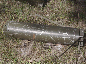
|
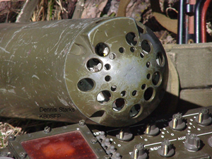 |
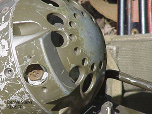 |
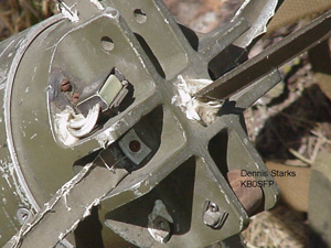 |
 |
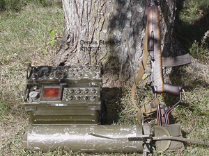 |

The central gold colored thing is the microphone.
Note all the holes in the front to let sound in and
protect the microphone from tree limbs.
|

|
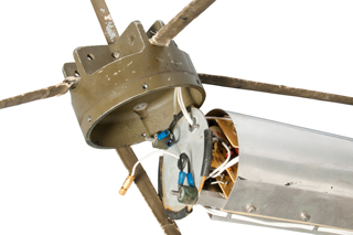
|
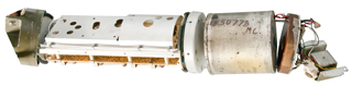
|
Battery
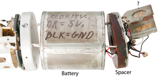
This is a battery type I don't recognize. If you
know about it please let me
know what it is.
|
Sound Observer (Locator)
Remote Microphone.
It's identical to the mike in the Acoubuoy.
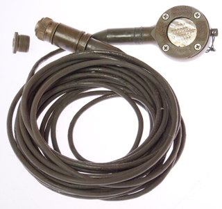
This is the same mike that's in the photo at left with
the question mark. The 5 socket connector is marked:
7004 Deutsh
DBA36-10-5SN-10-6032
The contacts are numbered 1, 2, 3, 4 (but no 5).
There's a knurled and slotted screw head on the back that
can be unscrewed about 1 turn, maybe to normalizing the
pressure inside to match atmospheric.
See RT-1185 for a similar
application.
Maybe one of the applications was to locate enemy small
arms or big guns?
|
3226670
Apparatus for determining characteristics of the ocean bottom,
Joseph
D Richard, 1965-12-28, - uses explosive gas to generate
accoustic pulse and condenser microphone
(2965877
Capacitive-type line hydrophone, Navy, 1960-12-20) to sense the
reflected waveform.
3555502
Aerial drop telemetering sensor,
Paul
D Davis Jr,
Edwin
B Neitzel,
Texas
Instruments, 1971-01-12, - "...seismic exploration by means
of an air-droppable telemetering sensor..."
3360772
Geophone,
Massa
Frank,
Dynamics
Corp of America, 1967-12-26, - piezo sensor, transmitter
& antenna all in one small unit - interesting
cites
&
cited
by.
3704764
Air deliverable seismic system,
Harold B Henderson,
Texas
Instruments, Filed: 1969-12-23, Pub: 1972-12-05 - a motor
rotates a cylinder until a pendulum is plumb, then feet extend and
the antenna is raised. Note TI and Vietnam time frame.
What is this?
Let me know.
Has the feel of "Metalhead" the dog robot in Black Mirror (
YouTube).
Does not call other patents but is cited by:
5434828
Stabilizer for geophone, Roger M. Logan, Ion Geophysical Corp,
1995-07-18 - adds bumps so it will not roll around when on the
bottom under water.
6531965
Modular open system architecture for unattended ground sensors,
Stephen G. Kaiser, Mark D. Hischke, Shannon Mary Nelson, Stuart
J. Collar, Dana Lynn Bourbonnais, Northrop Grumman Systems Corp,
2003-03-11 - the sensor modules look like those on the GSQ-154 & GSQ0160.
"unattended ground sensor" (Wiki)
mentioned many times.
History of the U.S. Army Research Laboratory -
page with mention of UGS.
6823262 Method for conducting seismic surveys
utilizing an aircraft deployed seismic source, Phillip Andrew
Bahorich, Michael Stephen Bahorich, Apache Corp, 2004-11-23 -
plane drops iron bomb w/o explosives, just it's weight hitting
the ground makes the signal.
6831699
Deployable monitoring device having self-righting housing and
associated method, Yu-Wen Chang, William Grainger, Michael
Johnson, William Traeger, Pablo De Los Rios, William Osterholm,
Chang Ind Inc, 2004-12-14 - egg shaped device with TV
camera.
20060010998
Autonomous reconnaissance sonde, and method for deployment
thereof, Roke Manor Research Ltd, 2008-05-20 - based on TV
camera in Clay pigeon (Wiki).
WO2016139503
- sounds like a seismic sensor glues itself to the ground
3806908
Perimeter intrusion detection system,
L
Bound,
A
Hunting,
Texas
Instruments, 1974-04-23, -
3859598
Aerial drop penetration device,
Jack
W Mcelwain,
Jr
Alvis D Stephenson,
Texas
Instruments, 1975-01-07, - a two part probe, the top stays
above ground and the electronnics and seismometer go deep,
sonobuoys are too expensive, see 3226670, braking action for both
soil and water applications,
Cites
sonobuoy related patents,
Mines for Noise
The Turd,
Gravel Mines (Wiki),
and the BLU-43 Dragontooth (Wiki)
were used as part of Operation Igloo White (Wiki).
More about land mines at Blasting
Machines/M21 Training Land Mine -
Description
Operation
When powered there is no
indication on the front panel that the receiver is
working. Pressing the test buttons to the right of the
display will light up each row of digits if the DIM control is
clockwise. If a handset is connected and the SQUELCH is
turned down you can hear hissing in the speaker.
GSQ-171 Directional Infrared Intrusion
Detector
An eBay ad showed the GSQ-171 beside the USQ-46
receiver. It has what appear to be Vietnamese markings.
What is this:
Contact me
Fig 1
 |
Fig 2
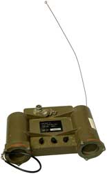 |
PP-6446A/USQ-46 Power Supply (Receiver, Test Set)
The following two units use "modular cylindrical building blocks).
SLOT Buoy (Wiki)
"Submarine-Launched One-Way Transmitter Buoy";
AN/BRT-1; NSN: 5820-01-233-6651
Patents
Wave Buoy
Wave rider buoys were used for station keeping the Glomar
Explorer.
2402143
Parachute pack, Gilbert
H Arenstein, 1946-06-18, - buoyant radio transmitter
parachuted from plane.- cited
by 21 patents.
2497852
Transmitter buoy, Gilbert
H Arenstein, 1950-02-21, - CW radio beacon, maybe to mark
a wreck.
2839920
Sea state wave meter, Thomas
G Macanespie, Glenn
L Martin Co, 1958-06-24, - designed to sense many
parameters, for radio transmission
3110178
Disposable accelerometer wave buoy, Marks
Wilbur, Robert
G Tuckerman, Willis
S Campbell, sNavy, 1963-11-12, - accelerometer has aluminum
cylinder and permanent magnet damper as part of a variable
capacitor that senses acceleration. For signal processing
see: Pierson and Marks, "Power Spectrum Analysis of Ocean Wave
Records,' Trans. Amer. Geophys. Union, v. 33, 1952. 100 kc FM
modulation on a 132 Mc carrier.
Sonobuoy
1154272
Marine Mine, Emil
Senger, Raimund
Sauter, Sep 21, 1915, 102/408
- a plug dissolves after a predetermined time scuttling
the mine
1308003 Apparatus for detecting and indicating the
presence of submarine boats, G.E. Elia (Italy), June 24, 1919, -
raises a flag when sub entangles net
1426337 Signaling apparatus for detecting
submarines, Sperry
Elmer A, Filed: Jul 9, 1917, Pub: Aug 15,
1922, 455/97, 441/11, 343/709,
174/138.00R, 294/111, 313/553,
114/240.00R, 313/243, 102/402,
174/77.00R, 455/99, 174/153.00R,
343/896, 200/83.00R - when net is entangled by a sub
the buoy sends a radio signal
203399 Improvement in Buoys, George D. Wyckoff, 1878-05-07, -
Floating surface marker buoy with bell.
2629083 Expendable radiosonic buoy, Barkson
Joseph A, Mason
Russell I, Mcnary
James C, Filing: Sep 21, 1944, Pub: Feb
17, 1953, 367/3, 343/709, 455/99,
441/33, 441/23, 343/705,
343/901 - CRT-1
1471547 Production of submarine signals and the
location of submarine objects, Chilowsky
Constantin, Langevin
Paul, May 19, 1917 (W.W.I) Oct 23, 1923
367/87, 367/174, 89/41.8,
89/41.7, 310/337 - uses the term "ultra-sonorous" 50
kHz to 200 kHz
1426337 Signaling apparatus for
detecting submarines, Sperry
Elmer A, Jul 9, 1917, Aug 15, 1922,
- triggered by net 455/97, 441/11, 343/709,
174/138.00R, 294/111, 313/553,
114/240.00R, 313/243, 102/402,
174/77.00R, 455/99, 174/153.00R,
343/896, 200/83.00R
2310017
Emergency transmitter, Hartman
B Canon, Joseph
L Swallow, Gard
Well Co, Wells-Gardner, App: 1941-05-05, W.W.II, Pub:
1943-02-02, - beacon Tx, no sensors
2311079
Transducer, Jr
Josephus O Parr, 1943-02-16, - seismometer
2361177 Method and apparatus for the
detection of submarines by airplanes, Constantin
Chilowsky, Apr 25, 1941, Oct 24, 1944, -
fluxgate probe towed by cable from plane flying in a circle
367/120, 102/419, 244/137.1,
367/130, 102/427, 434/6
1829474 Method and device for
establishing communication between aircraft in full flight and
the ground, Chilowsky
Constantin, 1931-10-27, -
2397844
Signaling
apparatus, Wallace
W DeWhurst (RCA)
Apr 2, 1946, 367/3,
138/89, 114/198, 455/99, D10/107, 441/11, 73/322.5 - sonobuoy
2402391
Submarine
detection, De
Witt R Goddard, Rca
Corp, Filed: Aug 30, 1943, Pub: Jun 18, 1946, 367/115,
124/51.1,
89/1.51,
367/112,
221/279
- time from explosive detonation until pulse
returned is range.
2420676 Submarine signaling apparatus, Robert
E Peterson, Jan 23, 1943 (W.W.II) May 20, 1947, 114/23,
367/150, 114/21.1, 116/27, 181/402, 114/21.3 - uses
the term "superaudible frequencies"
2422337
Submarine Detecting Buoy, C. Chilowsky, Jun 17 1947, 367/4;
441/11; 441/25; 441/26; 441/28; 455/99 - acoustic listen ing to
Sonorous and ultrasonorous vibrations is suing from the ship or
its propeller
Calls:
1249486
Sunken Ship Locating Device, Dec 11, 1917, 441/25; 242/156;
441/26 -
1195317
Observation-buoy and Fire Control for Floating Mines, Aug 22
1916,
1426337
Signaling Apparatus for Detecting Submarines, Aug 15 1922,
455/97; 102/402; 114/240.00R;
174/77.00R; 174/138.00R; 174/153.00R; 200/83.00R; 294/111;
313/243; 313/553; 343/709; 343/896; 441/11; 455/99 -
- sub hits net closing circuit keying a transmitter that uses
a code wheel to identify it's serial number.
1427560
Means for Detecting Submarines, Aug 29, 1922, - another net type
1430162
Apparatus for Detecting and Indicating the Presence of Submaring
Boats, Sep 26, 1922
1466284
Detecting System, (Western Electric) Aug 28, 1923, 367/122;
340/384.1 - multiple zone vibration detection
1610779
Signalling Apparatus, (GE) Dec 14 1926, -
1749444
Signal System, - police
2320610
Apparatus for Detecting and Indicating the Presence of Submarine
Boats - net type
2417830
Compressional wave signaling
device
2444069
System for receiving sounds in the presence of disturbing
noises, Leon
J Sivian, Bell
Labs, App:1945-03-02, Pub: 1948-06-29, - null out own
ship's propeller noise to allow hearing distant sub noises.
2447069
Signaling buoy, Jr
Philo Holcomb, App: 1940-02-05, Top Secret, Pub:
1948-08-17, - Sentinel buoys
with cable to shore.
2448713 Radio listening buoy, Hansell
Clarence W, Rca
Corp, Dec 2, 1944, Sep 7, 1948,
367/3,
343/709,
441/13,
455/99,
343/702
- listen for subs
2465696
Method and Means for Surveying Geological Formations, LeCoy C
Paslay, Mar 29 1949, 367/23; 114/245; 346/33.00C; 367/16; 367/20;
367/155 -
Calls:
1378960
Method and Apparatus for Detecting Under Water Vibrations, J.W.
Horton (WE), May 24 1921, 367/130 - submarine specific
1584613
Wave Detector, D.F. Comstock et al, May 11 1929, 367/130;
361/280; 361/283.1; 361/285; 367/129; 367/154 - sub detection
directional array of sensors
2212988
Apparatus for Transmitting and Recording Shot Moments, D.K. Kirt
(Gulf Oil R&D), Aug 27 1940, 367/77; 367/55 - seismograph
prospecting
2241428
Apparatus for Underwater Seismic Surveying, D. Silverman
(Standard Oil), May 1941,
2283200 Method
and Apparatus for Subsurface Mining, J.W. Flode, 1942 -
seismograph prospecting
2324378
submarine Prospecting, J.W. Flude, 1943 - seismograph
prospecting
2440903
Underwater Transducer, F. Massa (Brush Dev Co), May 4 1948,
367/160; 381/163; 381/190 - piezoelectric or magnetostrictive
transducers in towable rubber hose.
2511689
Submarine signaling apparatus, John
T Beechlyn, Raytheon,
1950-06-13, - various designs of magnetostriction using
multiple elements
2521136 Hydrophone,
A. Thuras, (USA) Sep 5,
1950, 310/26, 381/190, 367/168, 381/163
2586828
Radio buoy, Royal
V Keeran, 1952-02-26, - has sea anchor to
prevent drift

|
2593432
Automatically operated radio buoy, Freas
Raymond L, Apr 22, 1952,
455/96,
455/99,
244/149,
455/91,
343/705,
455/98,
441/11,
455/97,
343/709,
367/4,
343/902
Falls straight down from aircraft over
water. Rights itself, an explosive
extends the telescoping antenna, sends
distress signal, after timer scuttles.
2637862
Buoyant chamber scuttling device, Raymond
L Freas, 1953-05-12, -
|
2629083
Expendable
radiosonic buoy, Barkson
Joseph A, Mason
Russell I, Mcnary
James C, Filed: Sep
21, 1944, Pub: Feb 17, 1953,
367/3,
343/709,
455/99,
441/33,
441/23,
343/705,
343/901 -
2641751
Hydrophone Casing, (Navy), 367/173, Jun 1953 -
Calls:
806730 Device for locating and recovering sunken
articles, Dec 5, 1905
1252877 Means for indicating the position of
self-propelled vessels, Jan 8, 1918 - buoy released
from practice torpedo at end of its run
1292755
Submarine detector or
telltale, Jan 28, 1919 - net with alarm
1427560 Means for detecting submarine boats, Sperry
Elmer A, Aug 29, 1922 - net with alarm
2261513 Mechanical boat lifter and indicator, Nov
4, 1941 -
2361177 Method and apparatus for the detection of
submarines by airplanes, Oct 24, 1944 - fly in circle
with long cable attached to hydrophone
2396960 Means for locating lost aircraft Mar
19, 1946 -
Control Compass, (Navy), 361/280; 33/363.00Q, Jul 1953 -
Calls:
1639000 Wave modulation, Western
Electric Co, Aug 16, 1927 -
2036833
Tuning condenser arrangement
2116103
Compass for automatic
pilots, May 3, 1938 -
2277027 Telemetric system, West
Instr Co Inc, Mar 24, 1942 - servo
compass repeater
2319212 Photoelectric control device, May
18, 1943 - used to read compass rose
2346839
Baking utensil?
2363500 Gyro magnetic compass system, Sperry
Gyroscope Co Inc, Nov 28, 1944 -
Sonobuoy, R.H. Rines et al, Jun 5 1956, 455/99; 342/6; 367/3;
455/91; 455/107; 455/116; 455/129 -
Calls:
2063944
Means for Locating Crashed Airplanes, Jan 22, 1957, 116/210;
244/1.00R; 244/137.1 - based on sonobuoy technology
2063945 Diaphragm and Method
2063946 Sound Communication System
2063947 Compensator
2539594 System and Method of Communication
2361177 Method and Apparatus for the Detection of Submarines by
Airplanes, C. Cilowsky, Oct 24 1944, - flying in circle lowers
cable with hydrophone
2397844
Signaling Apparatus, W.W. Dewhurst (RCA), Apr 2, 1946, 367/3;
73/322.5; 114/198; 138/89; 441/11; 455/99; D10/107 - sub Tx buoy
2422337
2448713
Radio Listening Buoy, (RCA), Sep 7, 1948, 367/3; 343/702;
343/709; 441/13; 455/99 - very early sonobuoy
2448787
Apparatus for Detecting and Locating Enemy Vesels, (Ferrel Ind),
Sep 7, 1948, - above surface microphone(the wrong place)
Aug 7, 1956,
455/99,
342/5,
367/4
- shock absorber in cable to reduce noise & hydrophone
electronics in descending pod, not in floating part
2760180 Long range explosive sonobuoy, George
Sipkin, Filed: Oct 6, 1949, Pub: Aug 21,
1956,
367/2,
102/390,
367/133,
367/127
- EER type Underwater Sound Source
2790186
Sono-buoy stabilizer,
Lawrence
T Carapellotti, Navy, 1957-04-30, - To obtain stability of a
sono-buoy when floated in water, it is necessary to place the
center of gravity of the buoy well below the center of buoyancy. .
. . .the static center of gravity is not materially altered, but
wherein the dynamic center of gravity is placed well below the
center of buoyancy." without adding weight. This is done be
allowing water to enter the cavity left when the cable spool drops
down.
2817909
Training Device for Operators of Underwater Detection Appratus,
B.M. Taylor, et al, Dec 31 1957, 434/9; 434/10
Calls:
1731127 Signal Control System (railroad), Oct 8 1929
1859423 Sound Recording - multiple needles for echos
2039405 Remote Metering System (AT&T) -
2066156 signaling Means, Apr 25 1929, - relative motion
2206156 Conveyer?
2206036 Distance Measuring Apparatus and System, J.
Herson, Jly 2 1940, - optical aircraft altitude blind
landing
2329612 Apparatus for Training Aircraft Pilots, G.E. Hill et al,
Sep 14 1943, - includes real time position output
2332523 Ground Track Tracer and Landing Recorder, E. Norden et
al, Oct 26 1943, - servo controled pen recorders
2358793 Navigation Instruction Device, C.J. Crane, Sep 26 1944,
- scaled movement of student over floor
2373560 Sound Recording Method and Apparatus, J.M. Hanert
(Hammond Inst Co), Apr 10 1945 - adding vibrato
2375004 Training Apparatus, May 1 1945 - sound and recoil of a
real gun
2444477 Automatic Miniature Radio Range (A-N), 1948 - used with
pen recorder
2452038 Photoelectric Radio Compass Trainer Control, 1948 -
based on scale map
2459150 Interception Trainer 1949 - call "Link" patents:
1825462, 2099857
2828475
Remote Control or Measurement Indicating Means, (Sec of
Navy), Mar 19 1958 - Sonobuoy that adds direction to sound
in addition to just omni directional listening
Calls:
1571006 Signaling system, Western
Electric Co, Priority: Sep 8, 1920 (16
year delay) Pub: Jan 26, 1926 - motor based secret signaling
1592940 Secret signaling, Western
Electric Co, Priority: Sep 9, 1920 (16
year delay) Pub: Jul 20, 1926 - motor based secret signaling
1718497 Telemetric system, Gen
Electric, Jun 25, 1929 - servo remote
indicating
1732741 Duplex radio transmission system, Westinghouse
Electric & Mfg Co, Oct 22, 1929 -
combined audio & coded signals from a single source
1913512 Meteorological indicator, Jun 13,
1933 - radio transmitter hung below tethered - early
radiosonde
1928969 Well survey instrument, Union
Oil Co, Oct 3, 1933 - probe in pipe
sends attitude info to surface
2089987 Means for operating a repeating device, Pioneer
Instr Co Inc, Aug 17, 1937 -
2103847
Signaling, RCA - HF radio multiplex, Dec 28, 1937
2151747 Receiving system, Westinghouse,
Mar 28, 1939 - simultaneously receives AM and FM
signals
2177493 Fire detecting apparatus, works by
photocell seeing movement of light
2316317 Frequency-responsive network, Hazeltine,
Apr 13, 1943 - FM receiver for narrow band
modulation ( 1 kHz)
2334704 Automatic pilot, Nov 23, 1943,
uses magnetic sensors to control frequency generator (very
similar to how DIFAR encodes direction)
2357975 Frequency modulation system, Rca,
Sep 12, 1944 - receiver suitable for both AM and
FM reception
2361177 Method and apparatus for the detection of
submarines by airplanes, Constantin
Chilowsky, Oct 24, 1944 - see
MAD patents
2448787 Apparatus for detecting and locating
enemy vessels, Ferrel
Ind, Sep 7, 1948 - rotating
hydrophone and radio transmitter (DIFAR)
calls:
1610779
Signaling
apparatus, Gen
Electric, Dec 14, 1926 - an
underwater device that sends a signal when it receives
a signal. aimed at ship positioning, but could
also be used for sub detection? A
number of patents reference
this on.
2838741
Underwater sound detection system,
Warren
P Mason,
Bell
Labs, 1958-06-10, - SOSUS (
Wiki)
idea started in 1949) this is the correct time frame.
for use on a continental shelf where there's constant
depth where the low frequency cutoff is given by f = v/4H.
If H = 1640 feet (500 meters) (Wiki: Blake
Plateau) and v = 1500 meters/second; then
f = 1500/(4*500) = .75 per second or about 1 Hz.
This is very similar if not identical to waveguide propagation
modes (Wiki).
Uses a shore station.
Cites:
2432083
Hydrophone Jr
Robert Black, Frank
F Romanow, Oscar
A Shann, Bell
Labs, App: 1942-12-08, W.W.II, Pub: 1947-12-09, -
2885565
Azimuth sensing device, Davis Alfred, Army, 1959-05-05, - for
positioning an Az-El antenna in a remote location.
3022448
Modular sub-assembly, Feb 1962
3061249
Floating means,
Chipperfield
Victor James,
Ultra
Electronics, 1962-10-30, - parachute or roto-chute, bag
that's inflated to form a float,
3081466
Scuttling device, Paul
C Bailey, Navy, 1963-03-19, - dissolving plug below
water line
3093808
Air-dropped
miniature sonobuoy, Gimber
George A, Scarcelli
Albert F, Tatnall
George J, Secretary
of the Navy ,
Jun 11, 1963, 367/4,
441/33, 441/25, 343/709, 455/99 - Prior art sonobuoys were
3' long, 5" diameter and weighed 16 to 20 pounds
limiting aircraft time on station and had a max depth
of about 50'. This one is 15" long, about 3" dia
and weighs about 5 pounds with a max depth of 300'.
3116471
Radio
sonobuoy system, Jesse
J Coop, Dec 31, 1963, 367/3, 367/5, 367/113, 367/101, 367/126, 367/115, 318/638 -
In the present invention a
multi-beam directional hydrophone is utilized in a
radio sonobuoy system whereby an immediate quadrant
location and an accurate distance measurement of a
reflecting object from the multi-beam directional
sonobuoy can be obtained from a single pressure
pulse generated in the water area of interest.
- DIFAR
3132322
Radiosonic
buoys, Guy
Maes, Electronique
Appliquee, Feb 9, 1959, May 5, 1964,
367/4,
340/870.28,
343/710,
441/23,
455/127.1,
455/99,
441/11,
340/870.1,
343/880
3140886
Coupling Device,
E.J.
Cotilla,
George
A. Gimber, Navy, July 14, 1964, - for separating the float
from the hydrophone,
3141148
Underwater sound apparatus,
Theodore
F Hueter,
Honeywell
Inc, 1964-07-14, - "...phone arrays. The invention is
especially directed toward hydrophone arrays which are expanded
when low ered into the water and which is collapsed upon being
retrieved from the water." Not sonobuoy, maybe used from
surface ship? Incorporates the modern idea of increased
baseline between hydrophones.
3213409
Condition selector apparatus, Paul C Bailey, George A Gimber,
Navy, Aug 19, 1963, -
3234503
Drag chute and flotation device,
Francis
X Wojciechowski,
Harald
E Karlson,
Hoffman
Electronics, 1966-02-08, - parachute is onion shaped and (1)
pulls out telescoping antenna and (2) acts as a float. -I
question if it would last as long as the battery, also if it would
work after the sonobuoy goes down ten or twenty feet.
3248688
Ball configured electronic device,
George
J Shomphe,
Sanders
Associates, 1966-04-26, - spherical shape prior to launch -
free fall i.e. no parachute,
3262094
Discontinuous hollow cylindrical transducer,
Leon W
Camp,
Bendix,
1966-07-19, - polarized magnetostriction transducer 7 to 10
kHz
3276049
Deep water buoyancy apparatus,
Thomas
E Stixrud, Navy, 1966-10-04, - "A more particular object of
this invention is to provide a deep water buoy which utilizes the
vaporization of a liquid gas as a source of buoyancy. "
3276366
Deep depth line charge,
Robert
M Johnson,
Carl
A Axelson, Navy, 1966-10-04, - exploding line charge,
horizontal energy concentration, for detecting submarines. depth
can be set from 1,000 to 18,000 feet.
3281765
Minature Sonobuoy and Cable (ITT), Oct 25, 1966 - small dia
(0.030") cable which acts as a spring, Ni-Cad batt charged prior
to use.
Calls:
2422337
2641751 Hydrophne Casing,
Bernier
Jr Hector F, Mason
Russell I, Ripken
John F, Us
Navy, Filed: May 11, 1944, Pub: Jun 9,
1953,
367/173 - about playing out
the line supporting hte hydrophone below the buoy.
3093808
Air Dropped Miniature Sonobuoy, (Navy), Jun 11, 1963, 367/4;
343/709; 441/25; 441/33; 455/99 -
Directional Sonobuoy, (Navy), Dec 6, 1966, 367/4; 367/120;
367/129; 441/33 - weight driven rotating sensors
3309649
Sonobuoy with Depth Selection Capabilities,
Sanders
Assoc, Mar 14 1967, 367/4; 441/33 - spherical shape
3328750
Entrapped air flotation device, George
A Gimber, Roy
L Shipman, Navy, June 27, 1967, - instead of using a CO2
cartridge
3355544
Small diameter high tensile strength coaxial electrical cable, Vivian
G Costley James
E Cottrell, Navy, 1967-11-28, - "...diameter of no greater than approximately
70 mils and a tensile strength in excess of approximately 150
p.s. i. for suspending a hydrophone assembly of a sonobuoy...",
"This invention relates to
low noise electrical cables and more particularly to a new and
improved coaxial conductor of such construction as to have a
small diameter, reasonably low attenuation for a 400 kc.
electrical signal, watertight under high hydrostatic pressures
and yet being capable of supporting high tensile loads. "...predetermined depth many thousands of feet
below the water's surface."
3377615 Compliant suspension system, Sparton
Corp, Apr 9, 1968
3384867
Underwater transponder assembly including flotation unit,
Robert
M Bridges,
Bendix
Corp, 1968-05-21, - underwater unit uses glass balls to keep
upright, even at great depths.
3460058
Radio Sonobuoy,
Ronald
H Taplin,
ITT,
Aug 5, 1969, 367/4 - operates below thermocline, uses rotochute,
hydrophone at 12,000' down.
3480907
Neutrally buoyant hydrophone streamer, Joel D
King, Texas
Instruments, 1969-11-25, - used in towed linear array
3500209
Stabilized radio rescue beacon, Gordon
William Fletcher, Kenneth
William Lee-Kemp, 1970-03-10, - paddles in the water to
keep whip antenna in the up position
3517378 Underwater long-distance sound-detection
system, Barrett
Robert E, Us
Navy, Filed: Nov 6, 1959, (11 year
dealy), Pub: Jun 23, 1970,
367/2,
367/134
- EER explosive
3526002
Magnebuoy,
Ramond
C Waddel, 1970-08-25, - Proton Precession (kerosene) (
Wiki)
3543228
Sonobuoy suspension system,
Everett
Walter Farmer,
John
F Kaster,
Samuel
S Ballard,
Navy,
1970-11-24, - "An air-launchable, free-floating sonobuoy having a
deployable dynamic mass suspension system for reducing noise on
the sonic signal caused by excessive water flow at the hydrophone
in the lower unit. A cloth bag included in the lower unit fills
with water during its deployment. The mass of the water enclosed
in the bag constitutes a virtual mass which, added to the dry
weight of the Sus pension system, substantially reduces the
resonance fre quency of the suspension system; and the enlarged
bag substantially increases the lateral drag of the lower unit to
decrease the velocity of the water passing the lower unit."
3564489
Radio command buoy system,
Samuel
Pure,
James
R Howard,
Navy,
1971-02-16, - 291.4 MHz, 200 Hz to 200 kHz bandwidth, Seven Tones:
5.2, 6.2, 7.5, 8.7, 10.1, 11.8 & 13.8 kHz.
3622962
Free fall oceanographic beacon,
Clifford
L Winget,
Thomas
B Aldrich,
Navy,
1971-11-23, - See
Crypto\SOSUS\K129\2025_Update
3646505
Automatically deployable sonobuoy,
Woodrow
P Kirby,
Naval
Air Systems Cmd, 1972-02-29, - Rotochute, directional
hydrophone (41), maybe the SSQ-2?
3671928
Automatically energizable Sonobuoy, Aquatronics, Jun 20 1972,
367/4; 441/11; 441/33 - some similarity to acoubuoy.
3701319
Underwater sound signal for explosive echo ranging,
Carl
A Axelson,
John
R Hinves,
Elton
Y Mcgann,
Robert
M Johnson, 1972-10-31, - float, det cord, weight - line
charge explodes.
3720909
Directional Hydrophone System, Spartan Corp, Mar 13 1973, 367/173
- seismic sensors in sonobuoy
Calls:
3451040
Spring Suspension for a Low-frequency Geophone, W.R. Johnson,
)MarkProd Inc), Jun 17 1969, 367/183 -
Calls:
2751573
3344397
2390328
Directional Seismograph Pickup, R.J. Roberts (Std Oil), Dec 4,
1945, 367/185; 340/870.35 -
2856594
Seismic Detector, K.W. McLoad (Vector Mfg), Oct 14 1958,
367/154; 73/652 - underwater
3325778
Seismic Sonobuoy, S.S. Ballard (Sanders Assoc), Jun 13, 1967,
367/21; 330/51; 330/124.00R; 330/278; 367/66; 455/99 -
| 3377615 |
|
April 1968 |
Lutes |
| 3281765 |
|
October 1966 |
Taplin |
| 2435587 |
Compressional wave signaling device
|
February 1948 |
Harry |
| 3372368 |
|
March 1968 |
Dale et al. |
| 3539979 |
|
November 1970 |
Crall |
Apr 3, 1973,
181/116,
367/3,
367/145,
102/417
- used with sonobuoys, multiple charges triggered by radio from
the aircraft
3786403
Underwater Acoustical Detection, Navy, Jan 1, 1974, 367/4;
441/25; 441/26 - (Search-In-DEpth Concept of Acoustic Ranging =
SIDECAR),
Calls:
app 549209 Apr 19 1966 A.S. Will et al
app 452460 Apr 18 1965 Urick et al
app 502713 Oct 22 1965 Urick
| 2422337 |
June 1947 |
Chilowsky |
Submarine detecting buoy |
| 3222634 |
December 1965 |
Foster |
Underwater locating device |
| 3275976 |
September 1966 |
Farmer |
Bottom release mechanism for a sonobuoy |
3803540
Inflatable underwater platform, J
Mar, F
Vigneron, R
Gerrish, T
Garrett, A
Reynaud, Canada,
1974-04-09, - water is pumped into tublar structures what hold
hydrophones thus increasing the size of an array even though it
fits in a standard A size (5" x 3') container. Cited
by 16 patents.
|
Calibrators & Test Sets
3875548
Calibrator plug-in-module for sonobuoy, Robert
S Acks, Navy,
1975-04-01, - inserted between the hydrophone and sonobuoy
(how?).
4057778
Built-in test equipment for sonobuoy, Albert
M. Bates, Anthony
J. Madera, Navy,
1977-11-08, - for DIFAR
Includes block diagram of DIFAR sonobuy shown at left.
4092627
Calibration circuit for expendable sonobuoys, Donald
Murdock, Thomas
E. Stixrud, Navy,
1978-05-30, - a 10 Ohm resistor between the hydrophone and
ground is driven from a high value resistor to supply a 10
Hz test signal for one minute every 17 minutes.
4393483
Test set for a directional command active sonobuoy system
(DICASS), David
C. Hammond, Stephen
M. Elchenko, John
M. Tralies, Peter
W. Verburgt, Leon
R. Robinson, Navy,
1983-07-12, - flight line test set for aircraft, not
the sonobuoy.
5978646
Method and apparatus for simulating a LOFARgram in a
multipath sonar system, Henry
Weinberg, Navy,
1999-11-02, - Cites
28 prior art patents,
|
3921120
Float Actuated Release Mechanism, Sparton Corp., Nov 18 1975,
367/4; 116/209; 441/33 -
Calls:
| 2778332 |
January 1957 |
Talbot |
Means for locating crashed airplanes |
| 3093808 |
June 1963 |
Tatnall et al. |
Air-dropped miniature sonobuoy |
| 3140886 |
July 1964 |
Cotilla et al. |
Coupling device |
| 3220028 |
November 1965 |
Maes |
Radio-sono-buoys |
| 3309649 |
March 1967 |
Ballard et al. |
Sonobuoy with depth selection
capabilities |
| 3646505 |
February 1972 |
Kirby |
Automatically deployable sonobuoy |
| 3701175 |
October 1972 |
Widenhofer |
Hydrophone damper assembly |
Pinging controlled anti-torpedo device,
LeRoy
C. Paslay,
Navy,
App: 1950-10-24, Korea & Vietnam, Pub: 1976-03-16,
anti-torpedo filtered by speed of torpedo and triggered by
distance from own ship. Improvement on 2979015.
3944964 Air
Dripped Linear Acoustic Detector, (Navy), Mar 16, 1976,
367/4 -
3982222
Deep hydrophone string,
Robert
J. Urick,
Navy,
App:1965-10-22, Pub: 1976-09-21, - "...long range detection,
surveillance and communication by means of sonobuoys operating in
the deep sea and is more particularly concerned with a deep
hydrophone string operatively connected with a specialized
sonobuoy for this purpose. "
3991475
Depth selecting spool device, Navy, Nov 16, 1976, 116/209; 367/4;
441/24 -
calls:
| 3093808 |
June 1963 |
Tatnall et al. |
Air-dropped miniature sonobuoy |
| 3262090 |
July 1966 |
Farmer |
Sonobuoy depth selection mechanism |
| 3921120 |
November 1975 |
Widenhofer |
Float actuated release mechanism |
4004265 Thomas E. Woodruff,
4096598
Selected Depth Mooring System, R.J. Mason, 441/25, Jun 1978 -
Calls:
3631550
Mooring Devices, (EMI), 441/25, Jan 4, 1972 -
Modular buoy system,
Thomas
E. Woodruff,
Roger
I. Saunders,
Lockheed
Sanders Inc, 1977-05-31 -
Publication
number Priority date Publication date
Assignee Title
US2913198A *1955-10-04
1959-11-17 Leona A Bonbrake Sonobuoy
dispenser
US3010396A *1957-12-31
1961-11-28 Western Co Of North America
Selective firing apparatus
US3095814A *1960-06-30
1963-07-02 Tor W Jansen Dispensing apparatus
US3116689A *1959-07-07
1964-01-07 Halliburton Co Well perforating
apparatus and switch
US3142959A *1959-09-11
1964-08-04 Phillips Petroleum Co Range
control of self propelled missile
US3246707A *1964-02-17
1966-04-19 Schlumberger Well Surv Corp
Selective firing system
US3266372A *1964-08-27
1966-08-16 Harold J Mack Shipping and
launching container
US3368480A *1966-04-15
1968-02-13 Navy Usa Folding cone sonobuoy
delivery system
US3451306A *1967-01-26
1969-06-24 Susquehanna Corp Safe and arm
ejection system
US3768408A *1971-09-30
1973-10-30 Gearhart Owen Industries
Selective firing apparatus
US3787012A *1973-02-05
1974-01-22 Mc Donnell Douglas Corp Internal
ejector mechanism for stacked sequentially releasable
separable
4092627
Calibration circuit for expendable sonobuoys,
Donald
Murdock,
Thomas
E. Stixrud,
Navy,
1978-05-30, - a dual 555 timer (Wiki) circuit generates a signal
that's applied to a 10 Ohm resistor between the hydrophone and
ground to make a test signal. 15VDC supply, R5 & 10
Ohms. 17 minutes off and 1 minute one using a 10 Hz test
signal. The value of R5 is not mentioned so the amplitude of
the signal in series with the hydrophone can only be
guessed. If R5 was 1 Meg then the current would be 15V/1M =
15 uA. 15 uA * 10 Ohm = 150 uV.
4093934
Free-falling sonobuoy,
Robert
J. Urick,
Robert
L. Parris,
Navy,
App: 1965-04-28,
TOP SECRET,
Pub: 1978-06-06, -
4114137
Directional Sonobuoy, (Navy), 367/171; 441/1; 441/28, Sep 12 1978
- a spherical balloon is inflated with water to keep moving water
away from the hydrophone.
Calls:
768568
Sound transmitter and receiver, Submarine
Signal Co, Aug 23, 1904 - stereo
hydrophone with 2 long pole earphones
1345717 Acoustic device, Western
Electric, Jul 6, 1920 - carbon button
microphone mounted in a tear drop shape for use underwater.
3382481 Cantilever mounted hydrophone, Texas
Instruments, May 7, 1968 - marine
seismometer insensitive to cable strumming (5 Hz and above).
3803540 Inflatable underwater platform, Nat
Defence, Apr 9, 1974 - water pumped
into tubes to from a structure for sonobuoy (to make hydrophone
array) many patents
reference
this one
3864771 Deployable load buoyancy support
container or shelter system, Textron,
Feb 11, 1975 - telescoping sonobuoy construction
Mar 6, 1979,
367/4,
441/1,
439/391 -
4161716
Very low frequency sonobuoy (VLF sonobuoy),
Thomas
E. Stixrud,
Navy,
1979-07-17, - all about audio decoupling from sources of noise.
Patent Citations (4)
Patent
Priority
Pub
Assignee
Title
US3204708
1962-07-24 1965-09-07 Inst Francais Du
Petrole Method and apparatus for submarine
well drilling, using a flexible tubing as drill string
US3295489
1964-06-20 1967-01-03 Bossa
Eduardo
Plastic compound catenary for anchorage and pipeline
and/or cable support in any sea zone and depth
US3711821
1970-11-23 1973-01-16 Us
Navy
Sonobuoy suspension system
US3992737
1975-12-11 1976-11-23 Motorola,
Inc.
Suspension system for underwater equipment
4186370
Stabilized sonobuoy suspension, Raytheon, Jan 29, 1980, 367/4;
367/130; 441/11; 441/33 -
4189786
Radio Buoy Assembly, R.E. Adler, Feb 19 1980, 367/4; 367/5;
367/133 -
4246671
Buoy anchoring system, Richard
C. Swenson, Navy, 1981-01-27, -
4247143
Payload release mechanism, Stephen
G. Putman, Navy,
1981-01-27, -
4323988 Sonobuoy system, Albert
S. Will, Earl
A. Schuchard, John
P. Buckley, Armand
Cioccio, John
C. Hetzler, Jr., Sylvan
Wolf, Donald
E. Jefferson, Jim
B. McQuitty, Robert
A. Urick, Secretary
Of The Navy, Apr 6, 1982 (
TOP SECRET),
367/4,
367/173,
367/153 - A deep water
explosive echo ranging system capable of detecting high
performance submarines by using favorable acoustic paths
available at deep depths.
4357688 Low
cost sonobuoy, Navy, Nov 2, 1982, 367/4; 367/173 -
4358834
Self-deploying Buoy System, Navy, Nov 9, 1982, 367/4; 367/173 -
4404666
Quick deployment vehicle,
Arthur
P. Stevens,
John
De Matteo,
Richard
M. Beard,
Navy,
1983-09-13, - "A quick deployment vehicle (QDV) for implanting a
transponder or beacon on the ocean bottom in an upright position
exposed for receiving or transmitting acoustic signals."
4406631
Flotation device,
John R.
Dale,
Navy,
1983-09-27, - two liquids mix and form foam.
4493664
Sonobuoy Float Inflation and Depth Selection Initiators,
Navy,
Jan 15, 1985, 441/7; 222/5; 367/4; 441/26; 441/30; 441/33 -
open CO2 & select depth
4494024
One shot spring activated motor,
Gerald
W. Braun, undersea sensor systems,
Magnavox
Electronic Systems, 1985-01-15, - spring activated motor
that can turn CW or CCW depending on which holding rope is
cut/burned, maybe for setting depth?
4530269
Remotely Initiated Speration Latch Assembly, Burroughs Corp, Jul
23 1985, 89/1.14; 102/293; 102/378; 220/261; 367/4; 367/173; 403/2
- electrical match for seperation
4546459
Method and apparatus for a phased array transducer, John C.
Congdon, 1985-10-08, - DIFAR directional hydrophone
4590590
Sonobuoy Multiple Depth Deployment Apparatus, Magnavox, May 20
1986, 367/4; 441/25; 441/33 -
4656616
Volumetric transducer array and erecting structure,
Derek
J. Bennett,
Gene
Anderson,
Navy,
1987-04-07, - uses two umbrella structures, top and bottom,
with hydrophones on the wires between the tips to form a 8-sided
cylinder, greatly expanding the baseline between hydrophones.
4689773
Extendible sonobuoy apparatus,
John
C. Congdon,
Thomas
A. Richter,
Joseph
J. Slachta,
Magnavox
Government and Industrial Electronics,
4709359
End weighted reed sound transducer,
Rayford
A. Loftin,
Magnavox
Electronic Systems, Undersea Sensor Systems, 1987-11-24, - 4
hydrophones for DIFAR
4727520 (
RE33014)
Cable Deployment Unit,
Sparton
of Canada, Feb 23, 1988, 367/4; 367/3; 441/25 - hot wire
(35) melts line allowing spring to activate stop setting
hydrophone depth.
4901288
Compact cylindrical sonobuoy, Sparton Corp, Feb 13 1990, 367/4 -
4924445
Sonobuoy Cable Pack, Royal Navy, May 8, 1990, 367/4; 114/326;
367/3; 441/8 -
4927057
Automatic Infiltrator for Inflatable Articles, Inflation Tech, May
22, 1990, 222/5; 222/23; 222/41; 222/52; 222/63; 222/93; 222/94;
441/93 -
4493664
Sonobuoy float inflation and depth selection initiators,
John
R. Dale,
Secretary
Of The Navy, Jan 15, 1985,
441/7,
441/26,
222/5,
441/30,
367/4,
441/33
-
4560228
Electrical connector for sonobuoy launch system,
Roland
Bender, Navy, Dec 24, 1985, - pogo pins and metal contacts
4691305
Automatic attenuator for sonobuoys,
John
H. Kuck,
AF,
1987-09-01, - for use in
Missile Impact Location System (
Wili:
SMILS) "The attenuator for the sonobuoy device is divided into a
high gain, narrow band channel for detection of ping signals and a
low gain, wide band channel for detection
of impact signals.
4777627
Extendible sonobuoy apparatus,
John
C. Congdon, undersea sensor systems,
Magnavox
Electronic Systems, 1988-10-11, -
5073136
Collapsible sonobuoy floatation device,
Paul
H. DeWitt,
James
J. Majewski,
Thomas
A. Richter, undersea sensor systems,
Magnavox
Electronic Systems, 1991-12-17, - cylindrical bellows,
5076468
Squib Inflator Adapter, Halkey-Roberts Corp, Dec 31, 1991, 222/5;
222/91; 441/93 -
5117396
Large, air deployable, volumetric hydrophone array,
Brett
D. Castile,
Shelby
F. Sullivan,
Navy,
1992-05-26, - the key element, the STEM, is similar to a measuring
tape, but unlike the tape this device, when unrolled forms a
tube. The tube acts like the stay of an umbrella to support
the wires holding hydrophones. A major increase in the base
line between hydrophones in both horizontally and vertically.
"...a minimum of three horizontal booms radiating from
a central hub, sus pended at the array operating depth. The
booms are preferably comprised of metal tapes which are treated
in such a way that they curl and form tubular boom members that
can be flattened and rolled onto a com pact spool for storage
within an array deployment canister.
The present invention further incorporates loose lines of
hydrophones hung from pairs of points on the boom structure and
allowed to hang in arcs approximating catenaries. Utilization of
the hydrophone array disclosed in this application provides
considerable flexibility with the spatial arrangement of the
hydrophones as well as good acoustic performance.
...has ten db more array gain than any current array deployable
as an off-board sensor."
5119341
Method for extending GPS to underwater applications,
James
W. Youngberg,
AF,
1992-06-02, - GPS to Sonobuoy (fro P-3), acoustic signal to
underwater vehicle.
5197036
Sonar Array Mounting for Sonobuoy, Mar 23, 1993, 367/4; 367/153 -
5426617
Long baseline tracking system,
Reginald
J. Cyr,
Secretary
Of The Navy, Jun 20, 1995,
367/6
- uses multiple underwater transponders
6400645
Sonobuoy Apparatus, (
Navy),
Jun 4, 2002, 367/4; 367/3; 367/153 - six telescoping rods, like
the stays of an umbrella have wires at their tips supporting
hydrophones.
"Basically, in acoustic systems, the larger the
receive array, the greater will be the Sensitivity of the
System. However, a large receive array is incompatible with a
relatively Small ("A" size 5" x 3') Sonobuoy container. To
achieve the Sensitivity of a large receive array, many Small
Sonobuoys, or larger sized containers must be utilized. The
present invention provides a Solution to this incompatibility
problem."
1124917
Aerostat deployable from sonobuoy launch container, James Joseph
Bonang, Steven Lee Gall, Michael Jeffrey Greenfield, Randall L.
Mosten, Matthew Joseph Ragozzino, Boeing
Co, 2022-02-15, - sonobuoy deploys a blimp containing a
radio repeater that works for a group of sonobuoys to increase
their radio range by incfeasing the antenna height.
Magnavox
3299375
Elastic stretchable coaxial cable having constant capacitance
using woven or helically wound conductors,
Charles
S Thompson,
Magnavox,
1967-01-17, - for sonobuoy hydrophones
3336892
Cable dispensing and locking means,
Gerald
J Barry,
Thomas
B Harker,
Magnavox,
1967-08-22, - for sonobuoy hydrophones
Cites:
3035285
Explosively anchored buoy, Jr
Walter G Squires, 1962-05-22, - for marking applications
where buoy is under water until a timer runs out then it
surfaces.
3054123
Buoy with explosive anchor, Adolph
F Moeller, Navy, 1962-09-18, - "Navy dan buoy": "A
temporary marker buoy used during minesweeping operations to
indicate the boundaries of swept paths, swept areas, known
hazards, and other locations or reference points."
2722018
Float marker, Walter
V Mueller, 1955-11-01, -
3036542
Embedment anchor, Russell S Robinson, Pneumo Dynamics,
1962-05-29
2993461Embedment anchor
3603921
Sound transducer,
Robert
H Dreisbach,
Magnavox
Electronic Systems, 1971-09-07, - 4 lobe hydrophone for
sonobuoy
3656151
Digital function generation network,
William
E Richeson Jr,
Mike B
Feher (N4FS),
Magnavox,
1972-04-11,
341/147; 341/153 -
"In the early days of DIFAR there was no real
grayscale on the chart paper which indicated signal strength.
Essentially you either had nothing or a real dark line. My
logarithmic converter remedied that in that it allowed smooth
transitions as signal strength varied. Of course now there would
be so many better ways of doing it. However, at the time it
worked and everyone was pleased. 73 – Mike" See AQA-7 below.
4007316
Deferred action battery having an improved depolarizer,
Ralph
F. Koontz,
Magnavox
Co, 1977-02-08,
429/118; 429/220; 429/229 - sea water
activated
4086560
Secret depth sounder,
Thomas
F. Johnston,
Aaron
Z. Robinson,
Navy,
App: 1959-04-03,
TOP SECRET,
Pub: 1978-04-25, - uses recorded ambient noise as the signal
transmitter and a correlator processes the received signal.
4192913
Deferred action battery having an improved depolarizer,
Ralph
F. Koontz,
Lloyd
E. Klein, Magnavox Electronic Systems, 1980-03-11,
429/119; 429/220 -
4261853
Deferred action battery having an improved depolarizer,
Ralph
F. Koontz,
Lloyd
E. Klein,
Magnavox
Govt & Ind, 1981-04-14,
252/182.1; 429/118; 429/119; 429/220 -
4268912
Directional hydrophone suitable for flush mounting,
John
C. Congdon,
Magnavox,
1981-05-19,
367/163; 310/337; 310/365; 310/366; 367/164;
367/174 - for use on submarine
4494024
One shot spring activated motor,
Gerald
W. Braun,
Magnavox
Govt & Ind, 1985-01-15,
310/75A; 200/61.08; 310/273 - a squib
(resistor) severs a cord releasing a CW or CCW spring to drive a
shaft (for setting depth of hydrophone). Note some torpedo
gyroscopes use a very similar
squib released spring motor.
4546459
Method and apparatus for a phased array transducer,
John
C. Congdon,
Magnavox,
1985-10-08,
367/155; 367/157; 367/159; 367/165 -
DIFAR beam forming
4590590
Sonobuoy multiple depth deployment apparatus,
James
R. Toone,
Robert
L. Barker, Magnavox, 1983-11-29,
367/4; 441/25; 441/33 - See Fig: 53-21, 53-23, 53-24,
4611293
Method and apparatus for automatic calibration of magnetic
compass,
Ronald
R. Hatch,
Richard
G. Keegan,
Magnavox
Electronic Systems, 1986-09-09,
702/92; 324/245; 33/355R; 33/356 -
360 deg turn compensates for both soft and hard iron. 3-phase
Earth Induction compass (aircraft application?) [Hatch holds
many GPS related patents)]
4654832
Sonobuoy retaining and release apparatus,
Robert
L. Barker,
Magnavox,
1983-11-29,
367/4; 441/33 - Sonobuoy parachute,
see figs:
53-6,
53-7,
53-8
4660040
Target range sensing apparatus,
Norman
Grandos,
Magnavox
Govt & Ind, 1987-04-21,
342/128; 342/193; 342/68 - "Target
range sensing apparatus" - maybe a bomb fuze using FM-CW, or a
sonobuoy range detector?
4689773
Extendible sonobuoy apparatus,
John
C. Congdon,
Thomas
A. Richter,
Joseph
J. Slachta,
Magnavox,
1982-12-02,
367/3; 367/159; 367/165; 367/169; 367/173 -
DIFAR sonobuoy "The components typically include an
electronics canister, acoustic wave phase controls and one or more
active electroacoustic transducers. The components are attached to
a plurality of flexible support cables. The cables are attached at
their respective upper ends to the bottom of the canister and are
attached at their lower ends to the bottom of the tube. The cables
are collapsed during the pre-deployed state and tautly extended
during the deployed state. Axial guide strips are affixed to the
inner surface of the tube. The canister and transducer have
recesses engaging the strips in a sliding fit to prevent rotation
about the tube longitudinal axis during deployment. The electro
acoustic transducer may be mounted to the tube at a predetermined
axial location on the tube. "
4700100
Flexural disk resonant cavity transducer,
John
C. Congdon,
Thomas
A. Whitmore,
Magnavox,
1987-10-13,
310/332; 310/324; 310/326; 310/337; 367/155 -
improves the frequency response of
Helmholtz
cavity in the 1 to 2 kHz range.
4709359
End weighted reed sound transducer,
Rayford
A. Loftin,
Magnavox
Govt & Ind, 1987-11-24,
367/155; 367/161 - four vanes
4797841
Method and apparatus for automatic calibration of magnetic
compass,
Ronald
R. Hatch,
Magnavox
Govt & Ind, 1989-01-10,
702/92; 324/245; 33/355R; 33/356 -
3-phase Induction compass
4777627
Extendible sonobuoy apparatus,
John
C. Congdon,
Magnavox,
1985-06-26,
367/3; 367/159; 367/173; 367/4; 441/1 -
EP0098017A2
End weighted reed sound transducer, Rayford
A. Loftin, Magnavox
Electronic Systems, 1985-08-28, - four bars
4970703
Switched capacitor waveform processing circuit,
Peruvamba
R. Hariharan,
Robert
W. Downing,
Magnavox
Govt & Ind, 1990-11-13,
367/138; 367/122 - sonar beam forming
or sonobuoy?
5018116
Inter-element mounting for stacked piezoelectric transducers,
John
C. Congdon,
Magnavox
Govt & Ind, 1991-05-21,
367/165; 310/334 -
5046031
Method and apparatus for automatic flux-gate compass calibration,
Richard
E. Wanous,
Magnavox
Govt & Ind, 1991-09-03,
702/92; 33/356; 324/245; 73/1.76 -
compensates for loading & unloading the vehicle (not sonobuoy,
but shows a lot of understanding in fluxgate magnetometers as used
on DIFAR sonobuoy).
5073136
Collapsible sonobuoy flotation device,
Paul
H. DeWitt,
James
J. Majewski,
Thomas
A. Richter,
Magnavox
Electronic Systems, 1990-03-29,
441/7; 441/11; 441/21; 441/30; 441/32 -
Pagoda/ Accordion shape can be pressed flat for stowage.
5286462
Gas generator system for underwater buoyancy, Jonathan
E. Olson, Magnavox,
1994-02-15, - water + Lithium Hydroxide = Hydrogen
SONAR
Around August 2021 I realized that the displays used for
Sonobuoys and passive SONAR are identical. During W.W.II
it looks like they did NOT have frequency and/or bearing
waterfall displays which are the norm today. So I'm trying
to find when and who the waterfall display was introduced.
There are a number of Audio
Analysis patents on the SSQ-53A web page. They
typically show human voice or bird calls as the thing being
analyzed and often use the term "complex waves" which I think is code
for underwater sounds. Also see Ref 68.
From the web page: SQS
Series Sonars:
model
|
Freq
kHz
|
Pulse
mS
|
Range
k yards
|
Scan
RPS
|
| SQS-1 |
20 - 28
|
12/36
|
1.5/4/6
|
90
|
SQS-4
Mod 1
|
8
|
|
5.5
|
|
SQS-4
Mod 2
|
10
|
|
4.5
|
|
SQS-4
Mod 3
|
12
|
|
4.5
|
|
SQS-4
Mod 4
|
14
|
6/30/80
|
4.5
|
|
SQS-7
|
12
|
3/10/60
|
2.5/5/10
|
|
SQS-10
|
20
|
6/30/80
|
1/3/6
|
150
|
SQS-23
|
4.5/5/5.5
|
.005/.03/.12
|
1/2.5/5/10 |
150
|
Were the SQS-nn SONAR sets all after the searchlight
type. What was the nomenclature for the searchlight type?
2391678
Sound detecting and indicating system,
Schuck
Oscar Hugo,
Leon G
S Wood, Navy, App: 1944-08-14, W.W.II, Pub: 1954-12-21, - A
single ring of 36 magnetostrictive elements. This is the
"OMNI" system which is much faster than the Prior Art searchlight
system.
2405134
Distance measuring system,
Walter
J Brown,
John E
Shomer,
Brush
Development Co, App: 1942-08-03, W.W.II, Pub: 1946-08-06, -
FM CW special shape of variable cap plates.
2431854
Apparatus for suppressing reverberation,
Leon G
S Wood, Navy, App: 1944-08-03, W.W.II, Pub: 1947-12-02, -
uses narrow band filter to only listen to the Doppler shifted
frequency associated with the target thus eliminating other
returns.
2438580
Compensator for doppler effect,
Schuck
Oscar Hugo,
Navy,
App: 1943-11-06, W.W.II, Pub: 1948-03-30, - he worked for Hunt at
the Harvard Underwater Sound Lab. For searchlight type SONAR to
cancel the Doppler of the own ship motion.
2473974
Underwater sound detecting and indicating system,
Schuck
Oscar Hugo, App: 1944-05-18, W.W.II, Pub: 1949-06-21, - Omni
ping, motorized searchlight receiver.
2515154
Transducer, Charles
H Lanphier, Sangamo
Electric, App: 1946-07-15, W.W.II, Pub:
1950-07-11, -
2695371
Control transformer and generator, Herbert
O Barnes, Sangamo
Electric, 1954-11-23, - an electrical commutator for a
fixed SONAR array and synchronous drive for a CRT tube. SQS-4
2697822
Sound detecting and indicating system, Schuck
Oscar Hugo, Leon
G S Wood, App: 1944-08-14, W.W.II, Pub: 1954-12-21, - has
the look and feel of patent 2391678, SQS-4
2709796
Automatic target training, Isaac
P Rodman, Nolle
Alfred Wilson, Allen
A Chernosky, Leon
G S Wood, Navy, App: 1945-03-30, W.W.II, Pub: 1955-05-31,
- for searchlight SONAR. Cites 2666192 by Hunt et al. also see
2987698 for range gating.
2762447
Cavity radiometer, Walter
G Cady, Navy, 1956-09-11, - o improve the art ofunder water
radiation-pressure-measuring apparatus
2791756
Target doppler indicator, Leon
G S Wood, Paul
B Sebring, Navy, App: 1946-06-11, W.W.II, Pub: 1957-05-07,
- for active SONAR. Mentions: "The recorder may be any of several known
types of which an example is manufactured by the Sangamo
Electric Company, Springfield, Illinois, and described in a
publication of that manufacturer entitled "Instructions for Type
CAN-55070 Range Recorder.” see Sangamo patent 1350485.
2987698
Indicating a selected target echo in an echo wave train
obtained by echo ranging, Isaac
P Rodman, Nolle
Alfred Wilson, Allen
A Chernosky, Leon
G S Wood, Navy, App: 1945-03-30, TOP
SECRET, Pub: 1961-06-06, - range gating, Sangamo Electric Co electro-chemical
chart paper, trace gets much darker when return signal appears
- maybe the start of waterfall displays.
2991445
Echo ranging system, Haynes
James Burney, Charles
H Lanphier, Sangamo
Electric, 1961-07-04, - spiral sweep PPI (Wiki)
type CRT display of range and bearing. SQS-4
3016513
Fm echo-ranging system, Karl
S Van Dyke, App: 1943-05-26, TOP
SECRET, Pub: 1962-01-09, -
3497868
Echo ranging system, Charles
H Lanphier, Sangamo
Electric, App: 1957-06-17, TOP
SECRET, Pub: 1970-02-24, - A cylindrical
stack of four fixed rings of 48 transducers (7.5
degrees). Prior Art SONAR systems worked on the
searchlight principle where it took about 4 minutes to
make a 360 degree scan. An improved Prior Art system
was the "OMNI" where the transmitted ping was in all
directions but only a segment of the transducers were used
for receive as described in patent 2515154.
Mentions SQS-4 MOD 4 NAVSHIPS
92283 (A).
3613069 Sonar system, Cary
Boyd B Jr, Fenlon
Francis H, Gen
Dynamics Corp, Oct 12, 1971, 367/92,
367/104,
367/107,
367/101
- combines two Tx frequencies (Mixer Transducer
& Pump Transducer- higher SPL), 12, 48 & 60
kHz.
4194246
Noisemaker beacon, Ralph
P. Crist, US
Navy, 1958-05-12, -
4197591
Facsimile recording of sonic values of the ocean bottom,
Julius
Hagemann, App: 1958-08-04,
TOP
SECRET, Pub: 1980-04-08, -
4320474
Saturation
limited parametric sonar source, John
M. Huckabay, Reuben
H. Wallace, Secretary
Of The Navy, Mar 16, 1982, 367/138,
367/92
- phased array?
4777627
Extendible sonobuoy apparatus, John
C. Congdon, Magnavox,
1988-10-11, - DIFAR
4939699
Sonar system, Francis
J. Murphree, Henry
L. Warner, Edward
G. McLeroy, Navy,
App: 1966-12-08, TOP SECRET, Pub: 1990-07-03, - "A
sonar system having a sonar transmitter which is programmed to
broadcast two sets of several increasing frequency signals, with
the frequency gap between each set thereof sufficient to cause
them to distinguish between deep and shallow water targets,
respectively. A heterodyne receiver receives target
echoes of said sets of several frequency signals and converts them
to two sets of identical frequency signals which are then readout
as a single continuous target display signal."
4939702
Barrier sonar, Francis
J. Murphree, Secretary
Of Navy, Filed: Jul 19, 1968(12 year
delay) Pub: Jul 3, 1990,
367/138,
367/87,
367/93
-
4998224
System for providing improved reverberation limited sonar
performance, Mar 5, 1991
5138587
Harbor Approach- Defense Embedded System, (Navy), 367/136, Aug
1992
5144487
Expendable moving echo radiator, (Navy), 367/1; 367/137;
367/165, Sep 1992 - countermeasures equip
5235558 Choke point bistatic sonar, Harvey
C. Woodsum, Joseph
J. Stapleton, Gte
Government Systems Corp, Aug 10, 1993,
367/92,
367/104,
367/15,
367/908
-
5808580
Radar/sonar system concept for extended range-doppler coverage,
6018493
Sonar Suspension Apparatus, Dowty Maritime Sys, Jan 25,
2000, 367/16; 367/20; 367/153; 367/155; 367/165; 441/33 -
6707760
Projectile sonar,
Andrew
C. Coon,
Howard
Allen Lazoff,
Richard
Phillip Taschler,
Raytheon,
2004-03-16, - a surface ship fires special shells (explode at set
depth) and using sonar processes the returned sub echo.
Dr. Breed & Hughes
5134369
Three axis magnetometer sensor field alignment and registration,
Allen K.
Lo,
Wilbur
W. Eaton,
Jr.Ben
R. Breed, Raytheon (
Hughes),
1992-07-28, -
5239474
Dipole moment detection and localization,
Wilbur
W. Eaton,
Jr.Ben
R. Breed, Raytheon (
Hughes),
1993-08-24, - based on Anderson Localization (
Wiki)
5617099
Adaptive filtering of matched-filter data, Ronald W. Warren, Ben
R. Breed, Raytheon (
Hughes),
1997-04-01, -
Launching
Photo from Wiki
Sonobuoy
page
From Ships and Aircraft of the U.S. Fleet (2005):
The P3C Orion. . . tail-mounted ASQ-81 Magnetic Anomaly
Detector (MAD) and 48 external (fuselage) sonolbuoy chutes and
four in-flight reloadable (internal) chutes; a total of 84 buoys
normally are carried.
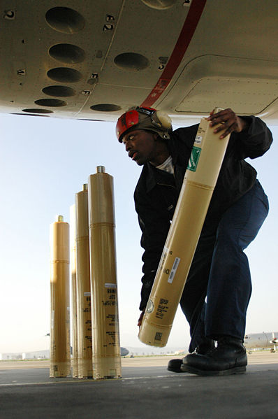 |
Note The silver cylinder on the top of each sonobuoy.
It's a gas generator that's electrically triggered.
Cartridge-Actuated Device = CAD
MIL-C-83124
An alternative to using compressed gas from a tank.
See patents directly below.
Fig 1 from patent 3905291:

|
2707904
Sonobuoy Dispensers, Breeze Corp, May 10, 1955, 89/1.51; 367/3 -
revolver,
3093808
Air-dropped miniature sonobuoy,
George
J Tatnall,
Albert
F Scarcelli,
George
A Gimber, US Navy, 1963-06-11, -
3228281
Tactical navigation display system,
Pliny
G Holt,
Navy,
1966-01-11, - mission from aircraft carrier, sonobuoy triangle
pattern & return to carrier at new position. looks like
aircraft instrument.
3266372
Shipping and launching container,
Harold
J Mack,
Albert
F Scarcelli, US Navy, 1966-08-16
3451306 Safe
and Arm Ejection System, Susquehanna Corp, Jun 24 1969, 89/1.1;
89/1.51; 102/259; 102/357 -
3905291
Cartridge-Actuated Device and Launching Assembly using same, G.T.
Corbin, Sep 16 1975, 102/430; 42/96 -
4026188
Modular Buoy System, Sandars Assoc, May 31 1977, 89/1.51; 102/351;
102/352; 102/354; 102/406 -
4263835
Sonobuoy Launcher System, Navy, Apr 28, 1981, 89/1.51; 89/1.3;
89/1.806; 89/1.818 - bouys loaded from outside
4397433
Revolving-cylinder jettison device for transporting and releasing
buoys on and from Aircraft, , Aug 9 1983, 244/137.4; 89/1.51;
89/1.801; 244/118.1 -
5052270
Multi-sonobuoy launch container with constant force spring, Navy,
Oct 1 1991, 89/1.51; 244/137.4 -
7278416
Pneumatic projectile launcher and sonobuoy launcher adaptor,
Lockheed-Martin, Oct 9, 2007, 124/72; 89/1.51 -
Magnetic Anomaly Detector (MAD) (Wiki)
Note that MADs need to be within a few hundred feet of the
ocean surface in order to detect a sub. They do not work
at high altitudes.
The Earth's magnetic field varies between 25,000 and 70,000
Gamma (aka: nanoTesla) (Wiki)
depending on the location.
These were originally called Magnetic Airborne Detectors (Ref 3)
and was developed by the NDRC (Wiki,
Executive
Order 8807 June 28, 1941) and was paired with the use of
sonobuoys.
Maximum range 1 to 2 thousand feet. I'm guessing the range
includes the depth of the sub, so the deeper the sub the more
likely MAD will miss it.
When I lived in Mountain View it was a very common sight to see
a P-3 Orion (Wiki)
landing or taking off from Moffett Field Naval Air Station (Wiki).
They had a "stinger" on the tail that held the magnetic anomaly
detector. Here's a Youtube
video of the MX-1361/ASQ-8 MAD
It appears to have 3 coils, each about 4" in diameter by 2"
thick made by TI
mounted in 3 orthogonal directions (X, Y & Z)
The ASA-65 is the motion compensator for the ASQ-81 MAD
system. That's to say that any motion of the P-3 will
cause the X, Y & Z components of the Earth's magnetic filed
to change. To back that out three coils can be placed over
the magnetic sensors and those coils driven from the output of
the ASA-65.
When testing a MAD a small portable "Gamma Slinger" is used that generates
a known (1045' c.g.s units) rotating magnetic field.
1045 Gauss converts to 104,500,000 nanotesla. Since the
Earth's field is about 50,000 nanotesla the Gamma Slinger is
about 2000 times as strong as the Earth's filed.
It's probably made using a modern permanent magnet rotated on a
shaft by a clock work where the shaft and clockwork are all non
magnetic. This test device could be used on the flight
line to check out the MAD system.
It can easily be detected at over 20 feet using the ASQ-81.
The AN/ASQ-208 is a digital processing type MAD system.
The ASQ-1, ASQ-1A, ASQ-3 and ASQ-3A was used in conjunction
with the CRT-1 sonobuoy
in W.W.II.
Ref pg 302,
Chapter 16, SOFAR, Harbor Defense, and other SONAR Systems,
Naval Sonar, NAVPERS 10884, 1953 (another source: NavalSonar.pdf)
The ASQ-3A was used as the basis of an magnetic survey of the
world.
Ref: Airborne
Geomagnetic Surveys by the United States Hydrographic Office,
Henry P. Stockard, USN Hydrographic Office, NAVIGATION,
Journal of The Institute of Navigation, Vol. 4, No. 8,
1955, pp. 320-323. modified to use the Vector Airborne
Magnetometer type 2A (VAM-2A)
NOL
vector airborne magnetometer type 2A (VAM-2A)
The Pave Mace system that used the Black Crow MAD sensor was
optimized to pickup the magnetic filed from ignition system in
Vietnamese vehicles (probably a cover story). (link
to external web page with photo of it). The plate to
the side of the dome with 3 rows of holes along the top and 3 more
rows of holes on the bottom has the feel of a slot antenna for VHF
or UHF signals, so more of a radio system than a MAD system.
If you have any definitive information let
me know.
It's not clear if this is a magnetic system or a VHF/UHF radio
system.
Jerry Proc: AN/ASQ-81 Magnetic Anomaly Detector - helium magnetometer
ASQ-8
The system weighs 150 pounds, occupies 7,700 Cu. In., is made
up of 6 boxes, uses 44 vacuum tubes and requires 700 Watts of
power (115VAC 400~ 3phase & 28VDC). The ASQ-10
weighs 32 lbs., has a volume of 1,200 Cu. In., uses 16 Vacuum
tubes and needs only 117 Watts of power. (from NAVPERS 10317-A)
MX-1361 Three Channel (X, Y, Z)
Magnetic Sensor
YouTube: Magnetic anomaly
detector - 3 orthogonal coils made by Texas
Instruments p/n: 29604 - This is not the anomaly detector
but rather the aircraft magnetic orientation sensor used
to drive the X-Y movement of the DT-37 magnetometer.
See References
below.
C820 Control Panel
Label on back: C-820/ASQ-8, NOas 53-340, 439:CGO
Sticker on front panel: RCAF Inspection Due 0439?, 23/68,
7690-21-801-0255, RCAF S69
Labels above grommets: P1301 and P1302 and the cables have been
cut off.
Changes 05 and 06 are scratched.
Side panel label: RCAF Instection Due, Batteries Installed 7 Dec
67, 7690-21-801-0255, RCAF S69.
There were internal batteries. What voltages?
Fig 1 Front
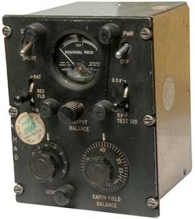
|
Fig 2 Back
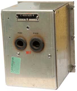 |
Fig 3 Inside top to right.
 |
Fig 4 Inside Maybe precision wire wound
resistors at right side.
 |
17H-4 Gamma Slinger
Wiring: A & B = AC input (Voltage TBD), C= ground.
Fig 1

|
Fig 2 North pole near nut.
 |
Fig 3 Motor: Hurst, Princeton, M.D.
about 60mm diameter
 |
Black Crow ASD-5
Wiki and other sources call this a MAD device used to detect
trucks along the Ho Chi Minh trail (Wiki)
in Vietnam, but I suspect that's a cover story since MAD
sensors need to be on a boom or stinger at the tail far away
from moving metal in the plane. But it's a plausible
cover story since MAD detects ferrous metal that trucks are
made from.
The ASD-5 was a system designed to detect spark ignition
systems. Since there are filters to specifically eliminate
impulse noise (Wiki)
I expect there are filters that pass impulse noise and reject
other sounds. Typical spark plug wires may be on the
order of 1 or 2 feet long (0.3 to 0.6 meters) so frequencies
around 1,000 MHz may be emitted. A test with a spectrum
analyzer on a Chi Com truck would give a more accurate
estimate. It would not detect a diesel engine.
My guess is that it also could detect the Hark-1 hand held
transmitters used by ground observers along the Ho Chi Minh
trail. Because the antenna array is on the left side of the
C-130 the body of the plane could be used to shield the
antenna from some RADARs that caused interference.
See: Ref 69
References
Aviation
Electronics Technician 3 & 2, Bureau of Naval Personnel,
Navy Training Course, NAVPERS 10317-A,
Ch. 14 Magnetic airborne detection equipment.
Ch. 15 Airborne Sonar and Sonobuoys. - SSQ-2B sonobuoy
contains an X-band or S-Band RADAR beacon receiver that
effects the output frequency in the 162 to 174 Mc range.
This is used as an aid in locating the sonobuoy.
I'm guessing to make them show up on the search RADAR is
bright dots.
The data on the ASQ-10 in the below table is my best guess
based on comments in NAVPERS 10317-A (page 401).
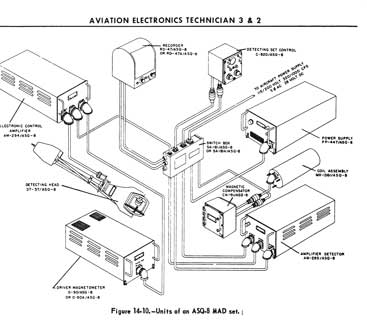
|
System Components
/ASQ-8
|
Description
|
/ASQ-10
|
/ASQ-81
|
| AM-294 |
Electronic Control
Amplifier
|
AM-1967
|
AM-4535
|
| PP-447 |
Power Supply |
|
O-90
O-90A |
Driver
Magnetometer |
|
| CN-19 |
Magnetic
Compensator |
|
| AM-295 |
Amplifier Detector |
|
DT-37
|
Detecting Head
(stinger)
|
DT-37B
|
|
RD-47
RD-47A
|
Recorder
|
RD-47
RD-47A
RO-32
|
|
SA-181
SA-181A
|
Switch Box
|
na
|
|
C-820
|
Detecting Set
Control
|
C-2548
|
|
MX-1361
|
Coil Assembly
|
MX-1361 |
|
|
TR-218
The Influence of the Natural Enviornment on MAD Operations
1969 - The ASQ-10 will be followed by the ASQ-81 on the
P-3 Orion. The ASQ-81 uses an optical pump type
magnetometer (Wiki)
rather than the flux-gate type magnetometer used on the ASQ-8
and ASQ-10.
YouTube - Andrew Ochadlick: Optically Pumped Magnetometer
Sensitivity and Helium-4 Energy Levels 2015 - Part1 (theory), Part 2 (ASQ-81
details), Part 3 (Uncertainty Principal) - very technical/physics. -
Google
Search "Princeton Lorentz Violation"
The War against Trucks, Aerial Interdiction in Southern Laos
1968 - 1972, Nalty, (WarAgainstTrucks.pdf)
Magnetic Anomaly Detector (MAD) Patents
Also see
the MAD
patents on the Flux Gate Patents web page.
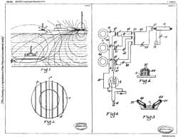
|
GB130050
Improvements in Means for the Detection and Location
of Metallic Bodies, particularly applicable to
Detecting Submarines, Vannevar
Bush (Wiki),
1919-07-31, - 3-axis magnetic detector that can be
manually turned on shaft. |
|
2361177
Method
and apparatus for the detection of submarines by
airplanes. Constantin
Chilowsky, Filed: 25 Apr 1941, Pub :24 Oct 1944, 367/120,
102/419,
244/137.1,
367/130,
102/427,
434/6
- Referenced
by 35 patents - not MAD but rather audio
|
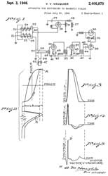
|
2406870
Apparatus
for responding to magnetic
fields, Vacquier
Victor V, Gulf
Research Development Co, filed: Jul
21, 1941, Pub: Sep 3, 1946, 324/253,
102/417, 33/361, 318/647, 324/326, 324/345, 324/255, 340/870.33, 102/427
This is THE MAD patent and is referenced by a
very large number of others.
|
The
following detectors are towed on a cable from a plane flying at
300 feet above the water:
2379447
Antisubmarine device, Lindsey
Henry A D, Jul 3, 1945, 102/417, 102/212, 340/551, 324/247,
324/67, 307/652, 324/258, 340/552
2404806
Submarine detector, Lindsey
Henry A D, Jul 30, 1946, 340/850, 102/402, 324/247, 324/331
2415808
Detection of large magentic bodies, Oliver
E Buckley, Bell
Labs, App: 1941-07-31, TOP SECRET,
Pub: 1947-02-18, - "The invention is particularly applicable to
the detection and location of submerged submarine or other vessels
having hulls of magnetic material but it is applicable as well to
the detection and location of other magnetic bodies, Such as large
magnetic Ore deposits."
2424772
System for detecting magnetic masses, Frank
Rieber, Interval
Instr Inc, Jul 29, 1947, 324/247, 324/331, 322/1, 324/257,
322/59, 340/870.32
2485847
Combination magnetometer and gradiometer, Otto
H Schmitt, Navy,
App: 1944-09-23, (Secret?), Pub: 1949-10-25, 324/244; 340/870.33;
324/255 - two sensors in each wingtip, sum and difference outputs.
Cites 6 including:
2238072 Method and means for locating concealed bodies, Dale H
Nelson, William D Buckingham, Western Union Telegraph Co,
1941-04-15, 324/67; 102/406; 324/326; 324/243;
324/345; 405/173 - "...for locating and determining
the depth to which a cable, or other body capable of afiecting,
distorting and/or producing magnetic lines of force, is buried
in the ground or otherwise concealed, and more particularly to
locating and determining the depth to which submarine cables and
the like are buried in the bed of the ocean or other body of
water."
2549845
Ship's magnetic submarine detector, James
C Mouzon, Edward
S Lamar, Bardeen
John, 1951-04-24, - big coils on surface ship to detect
subs.
2549857 Cable-suspended aerodynamic
body, Schonstedt
Erick O, Apr 24, 1951, 324/260, 324/262,
114/24, 244/3, 74/5.00R,
324/331, 324/246, 33/397,
33/366.11
2555209 Method and apparatus for measuring the
values of magnetic fields, Gary
Muffly, Vacquier
Victor V, Gulf
Research Development Co, Filed: Nov 1, 1943, Pub: May 29, 1951, 324/246,
324/345, 324/253, - aligns MAD
sensors with Earth's magnetic filed
2632884 Orienting mechanism for magnetic
detector devices, Murphy
Paul M, Mar 24, 1953, 324/253, 318/647,
324/246, 324/331
2696602
Compensated
magnetometer, Richard
Evans Chauncey, Dec 7, 1954,
324/253, 324/345 - uses term "magnetic
anomalies"
3039559
Sound producing device, William
M Ellsworth, Pneumo
Dynamics Corp, 1962-06-19, - a couple of CO2
like pressure cartridges holding Hydrogen and Oxygen
fill a rubber balloon which then is exploded
producing water vapor which causes a strong
implosion or cavitation.
3258687
Wide range linear fluxgate magnetometer, J.P.
Heppner & H.R. Boroson, NASA, Jun 28 1966, -
range 1 gamma to 10E-5 Gauss.
3412371
Detection system, Arnold
A Shostak, Navy,
1968-11-19, - magnetic micro pulsations
3530375
Aircraft magnetometer system with means to
compensate said system for disturbing magnetic field
generated by the aircraft, Fransiscus
A Passier, Navy,
1970-09-22, -
3644825
Magnetic detection system for detecting movement of
an object utilizing signals derived from two
orthogonal pickup coils, Paul
D Davis Jr, Thomas
E Mccullough, Texas
Instruments Inc, 1972-02-22 -
Cited
by 133 patents. - two coils allows determining
direction of movement, like trucks along road - Outdoor Intrusion
Detectors
3697869
System for generating compensating signals for magnetic effects of
aircraft on mad system, Myron
M Greenberg, Steven
A Macintyre, Navy,
1972-10-10, -
------------------ Helium Magnetometer (Wiki)
-------------
3577068
Optically pumped magnetic gradiometer, Richard
C La Force, Atlantic
Richfield, 1971-05-04, -
4546317
Free nuclear precession gradiometer system, George
F. Hinton, Navy,
1985-10-08, -
4766385
Underwater buried mine classifier, Donald
G. Polvani, Westinghouse
(Northrop
Grumman), 1988-08-23, -
5182514
Automatic compensator for an airborne magnetic anomaly detector, Joseph
A. Rice, Jr., TI,
App: 1974-11-19, TOP SECRET,
Pub: 1993-01-26, - mentions it's for the AN/ASQ-81.
SONAR Countermeasures
Also see Torpedo
Countermeasures (some are the same but some are different)
You see this in movies like The Hunt for Red October or
Crimson Tide. A small can is ejected from the sub and a
stream of bubbles comes out of it.
2710458
Underwater acoustic decoy, Donald
G Reed, App: 1945-06-14, W.W.II, Pub: 1955-06-14, -
torpedo that sounds like a sub for training SONAR operators.
2901997 Sound generator, Arthur
H Brooks, Sep 1, 1959 (14 year delay), 116/27,
116/137.00R, 102/418, 367/1 -
2981927
Underwater sound transmitter See below
3180295
Submarine simulator, Niederer
Otto Christopher, Navy,
1965-04-27, - a special torpedo with mag tape loop,
3194207
Underwater
sound sources, Dunne
Brian B, Gen
Dynamics Corp, Jul 13, 1965, 116/27, 367/142 -
electric motor driven noise maker + flotation device,
cylindrical shape (torpedo tube or smaller?) 3771115 Simulated
submarine target apparatus, McLinden
Hugh, - a viscous,
gelatinous material having metalic particles suspended in
it, is ejected by the sub to form a hollow bag-like structure
which is filled with water.
3408621
Submarine tracking apparatus, Franklin
A Dobson, Philco
Ford (Space Systems Loral), App: 1961-02-14, cold war,
Pub: 1968-10-29. - noise maker magnetically attached to sub. "NATO Designed
Magnetic Noisemakers to Track Soviet Submarines. The Plan Failed."
Book: Hunter Killers, by Iain Ballantyne (Ref 59)
3612211
Method of producing locally occurring infrasound, William
T Clark, 1971-10-12, - maybe similar to the
Holosonics (Wiki)
system that uses ultrasonics to generate an audio sound.
3786405
System for low-frequency transmission of radiant energy, M
Chramiec, W Konrad,
Raytheon, 1974-01-15, - underwater sound generation
3872421
Standing wave acoustic parametric source, Peter
H Rogers, Buren
Arnie Lee Van, Navy,
1975-03-18, - underwater sound generation
3891961
Sonar countermeasure, Rudolph M Haisfield, Navy,
App: 1961-02-27, TOP SECRET,
Pub: 1975-06-24, - phase shift with <1 Hz frequency
difference. for submarines
3964013
Cavitating parametric underwater acoustic source, William
L. Konrad, Navy,
1976-06-15, - bubbles provide for non-linear mixing
4183008
Noise making device, Ralph
P. Crist, Navy,
App: 1958-05-12, TOP SECRET,
Pub: 1980-01-08, -
4194246 Noisemaker beacon, Ralph
P. Crist, Secretary
Of The Navy, Mar 18, 1980 (32 years
delay=TOP SECRET), 367/1,
441/22, 441/12 - 10 to 100 kHz output
4214313
Multiple sonar masking and jamming countermeasure
system, Keith
E. Geren, Warren
A. Sauer, Donald
A. Young, Navy,
Pub: 1961-04-27, TOP
SECRET, Pub: 1980-07-22, - noise
jamming for passive sonar over 5 to 70 kHz range and
maybe (Wiki: Range
gate pull-off, or Radar
jamming and deception)
5117731
Tactical
acoustic decoy, Mark
A. Mendenhall, Secretary
Of The Navy, Jun 2, 1992,
89/1.816, 102/348, 367/1, 102/501 - mounts
on ship and jamms infrared, sonar & microwave.
5268875
Acoustic decoy, John
D. Charlton, Navy,
App: 1967-05-11, TOP
SECRET, Pub: 1993-12-07, - contionous
loop tape with multiple tracks with staggered heads.
6252822
Countermeasure device with
air bag hover system and pressure compensated
acoustic projectors, Robert
J. Obara, Secretary
Of The Navy, Jun 26, 2001, 367/1
- uses compressed air for both depth control
and noise making
Maybe called sonar counter counter measures was a
type of sonar that was difficult for an enemy to
hear. Maybe
done using a pseudorandom sequence of frequencies called direct
sequence spread spectrum when done with radio frequency signals.
5301166
Remote control command system, John
D. Charlton, Navy,
App: 1967-06-29, TOP SECRET,
Pub: 1994-04-05, - applies to either radio or sonic signaling.
Sound
Ranging
One meaning of Sound Ranging (Wiki)
is to locate explosions (like a gun firing) beginning in
W.W.I. Based on measuring the differences in the time of
arrival of the gunshot sound at multiple microphones. It's the
nature of a gunshot that the sound only lasts for a fraction of
a second. There is not enough time to turn a bearing dial
back and forth to determine the bearing so this equipment needs
to work without a human in the loop.
Another meaning of Sound Ranging is to get the bearing on a
source of sound. This was done by the Navy using binaural
headphones. Based on human hearing being able to determine
the direction of a sound. This we the first form of
passive SONAR. The sound of a ship or submarine is
continuous so there's time for a human to use their hearing to
determine the bearing to the source of the sound.

|
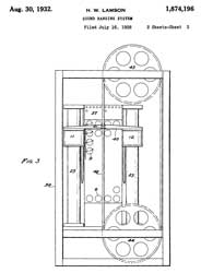 |
1874196
Sound ranging system, Horatio
W Lamson, General
Radio, 1932-08-30, -
A pair of microphones (1 & 2) pick up sound.
A pair of delay lines ("lag" or "retardation" lines15
& 16) are tapped by movable coils (11 & 12) which
when adjusted by the operator wearing binaural headphones
(75 & 76) displays the bearing to the sound.
Since this is a time delay system it is also frequency
independent.
Very similar to the Fenwick time delay beam steering
antenna patent.
|
|
|
1901342
Sound ranging system, Horatio
W Lamson, General
Radio,1933-03-14, - like 1874196 except has six
microphones and delay lines.
|
Hydrophones
A hydrophone (Wiki) is the
common sensor for sonobuoys and can be deployed at various
depths. A sonobuoy might have many depth settings that can
be set prior to ejecting it from an aircraft. This is
important because of what's called the thermocline (Wiki) which
is where the temperature of the water changes rapidly. This
changes the speed of sound (Wiki).
This causes the sound to change direction just as light will be
bent by a change in refractive index (Wiki).
And just like light there's conditions where the bending acts like
a mirror and all the sound (or light) is reflected off the layer
instead of just changing angles. So if the hydrophone is on
the wrong side of the thermocline it may not hear a sub that's on
the other side. The key parameter is how the water
temperature changes with depth which is measured by a Bathythermograph.
Arthur J. Mundy coined the term "hydrophone in the following
patent:
793896
Submarine signal, Arthur
J Mundy, Submarine
Signal Co, 1905-07-04, - "The invention relates to that
portion of a submarine signaling system which includes the means
for taking the sound-signals conducted by the water from a
submerged signaling apparatus from the water and transmitting
them, preferably electrically, to a telephone receiver on a
vessel. This portion of the apparatus as a whole I have named a
'hydrophone.” The part of the hydrophone which is immersed in the
water and receives sound impulses from it and transmits them I
term the "hydrophone-transmitter,” or, for short, the
'transmitter.” The part which receives the impulses from the
transmitter and delivers the sound to the hearer I call the
'hydrophone-receiver," or for short, the "receiver."
See the SSQ-53A\Audio Analysis
web page for the analysis of the sounds from hydrophones.
YouTube: PeriscopeFilm: Sounds in the Silent Deep
Hydrophones Underwater Sound Documentary, Moody Institute of
Science, Educational Film Division, "Sounds in the Silent Deep",
27:13, @4:33
underwater Disk microphone,
@5:35 Hydrophone,
5:56 SONAR, @9:50
URI study marine animal sounds (Vibralyzer, I can not read patent
number, Kay Electric Co. may be the same as Ohmega Lab), The
Analysis of Bird Songs by means of a Vibralyzer; Kay 3090-A
Vibralyzer - see SSQ-53A\Audio Analysis
1345717
Acoustic device, George
B Thomas, Western
Electric, 1920-07-06, - omni-directional
1393471
Submarine signaling, Raymond L Wegel, Western
Electric, 1921-10-11, - directional
1681963
Magnetophone, Robert
L Williams, Submarine
Signal Co, 1928-08-28, - - used directly with earphones
1803257 =
RE20680
Piezoelectric device, Charles
B. Sawyer, Brush
Development Co, 1938-03-29, -
2222056
Piezoelectric device, Alfred
L W Williams, Brush
Development Co, 1940-11-19, - lollypop shape
2353089
Transducer, Harry
B Shapiro, Brush
Development Co, App: 1942-03-26, W.W.II, Pub: 1944-07-04, -
2405472
Diaphragm, Tuttle
William Norris, General
Radio, App: 1934-06-12, Top Secret,
Pub: 1946-08-06, -
2434900
Sonic translating device,
Jr Robert Black, Frank
F Romanow, Bell
Labs, App: 1943-07-14, SECRET, Pub: 1948-01-27, -
2576155
Submarine compressional wave receptive apparatus, Horace M Trent,
1951-11-27, - piezoelectric transducer in rubber dome filled with
Castor Oil.
2589403
Transducer construction and method, Franz
N D Kurie, Navy,
App: 1943-12-14, Pub: 1952-03-18, - bonding Rochelle salt to metal
with min. capacitane and good mechanical coupling.
2594948
Electromechanical transducer unit, Thomas
E Lynch, Brush
Development Co, 1952-04-29, - crystal encased in petroleum
jelly for use in photograph pickup
2602836
Instantaneous (audio) frequency analyzer, Harry
R Foster, Elmo E
Crump, Ohmega
Lab, 1952-07-08, 324/76.29; 704/276; 324/76.19; 324/76.68;
324/76.44 - Vibralyzer?
2615078
Frequency analyzer system, Harry
R Foster, Elmo E
Crump, Ohmega
Lab,1952-10-21, 324/76.19; 101/DIG.37; 346/33R; 704/205;
360/137; 324/76.13 - Vibralyzer? Sonogram (Wiki: Spectrogram)
2774035
Magnetostrictive frequency analysers, Martin
R Richmond, Blitz
Daniel, Raytheon,
1956-12-11, - maybe for ground based radar
3603921
Sound transducer, Robert
H Dreisbach, Magnavox,
1971-09-07, - hydrophone, cited
by 15 patents
3803546
Broad band hydrophone, R Leon, Navy,
1974-04-09, - 4 cantilevered elements, 30 to 1000 Hz,
3903497
Opto-acoustic hydrophone, Morton
Stimler, Zaka
I Slawsky, Navy,
1975-09-02
A hydrophone (Wiki) is
an underwater sound sensor. On purpose I did not call it
some type of microphone because that would imply it can only
respond to sound within the frequency band which human ears can
hear. So, I think, sensor (Wiki) or
transducer (Wiki)
are better terms to use. The key reason for that is most
SONAR (Wiki)
involves ultrasonic frequencies.
An early piezo electric material used for hydrophones was
Rochelle Salt (Wiki)
which can be made from ingredients from the grocery store using
instructions from YouTube. Since it's water
based, getting water on the crystal will dissolve it, so maybe
not idea for an underwater application. Barium Titanate (Wiki)
is another piezoelectric (Wiki)
material used for hydrophones. Although know in the W.W.II
time frame, Titanium was not readily available in war time, so
Magnetostriction (Wiki)
was used for hydrophones early in W.W.II, like used on the CRT-1 sonobuoy.
See my Magnetics web page for an example of Terfenol-D
material.
Got this hydrophone from
Fair Radio. It consists of a
bladder just under five feet long and about three inches in
diameter filled with mineral oil (or something similar).
Inside there are eight cylindrical Rochelle Salt Crystal
doublets, each about three inches long with about a three inch gap
between sensors (series or parallel connection?).
In the
Combat
Information Center magazine for July 1944 (Vol. 1 No. 5)
there's an article on harbor defense that mentions both a sonobuoy
with vertical hydrophone array (radio has 12 mile range and
hydrophone has 1,000 yard range) as well as multiple hydrophones
laid on the bottom and connected to multi-conductor cable.
At the cable end of the hydrophone is a matching transformer with
25 Ohm output impedance. Frequency response of 1Hz to 20 kHz
(i.e. young human hearing range).
The internal construction seems to be steel cylinders spot welded
to two steel rods that tie them toghther. The crystals are
glued into the cylinders and wired in parallel.
If buried in the ground as is the mineral oil will leak out
leaving air voids. If repackaged in a PVC pipe the sound
would travel up and down the pipe wall which doesn't happen with
the current rubber bladder. So maybe some type of flexable
hose would be a good replacement?
The idea is to bury it and have excellent low frequency (below 20
Hz) response. The
Infra sound
sensors use garden hose with a pin hole leak.
Official Description:
Hydrophone, U. S. Navy
Harbor Detection, Sonic, NT-51038F; P/O type JR-1 Harbor
Detection Equipment.
Sensitive listening, frequency range 1 - 20 thousand
cycles per second; with 8 Rochelle Salt Crystal Doublets
each approx. 3" x 2" x 1", in metal frame w/matching
transformer to 25 ohm line, in Castor (?) Oil, encased by
heavy rubber jacket 56" long x 2 1/2" in diameter; with 9
foot rubber covered cable 1/2" O.D. w/2 flexible copper
wires insulated, plus 2 steel strain wires; to be used
down to 400ft. depth while withstanding high pressure
explosion waves. Mfg by Brush Development Company. |
How can the transformer work over that frequency range?
3 Feb 2012 - When the 999 average spectrum plot finishes I'll have
a look at the impedance.
Fig
HP1

|
Fig HP2 Transformer

|
|
|
White
|
Red
|
Black
|
Green
|
Blue
|
Case Ground
|
White |
-
|
Opn
|
Opn
|
Opn
|
Opn
|
|
Red
|
-
|
-
|
Opn
|
Opn
|
Sht
|
|
Black
|
-
|
-
|
-
|
Sht
|
Opn
|
|
Green
|
-
|
-
|
-
|
-
|
Opn
|
|
Blue
|
-
|
-
|
-
|
-
|
-
|
The Red and Blue terminals are physically in line.
The Black and Green terminals are physically in line.
The White wire is not an electrical connection but rather
is where a couple of steel cables attach for supporting
the weight of the hydrophone.
It's not clear what this is.
|
HP 4395A Plot 1 Hz to 20
kHz RBW: 1 Hz, True RMS detection, 16 averages:
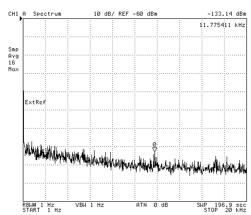
|
HP 4395A Plot 1Hz to 20 kHz
RBW: 1 Hz, True RMS detection, 999 averages (54.6 hours):

|
HP 4395A Z transform
Impedance Real & Imaginary

|
HP 4395A Z transform
Hydrophone Impedance Smith Chart with Marker List (It's a
50 Ohm device!)

|
Hydrophone Patents
The Submarine Signal Company (
Wiki)
developed the first hydrophones. They received a block of
patents all with the same application and publication dates.
The idea was to ring a bell under water and hear that sound with
an underwater microphone.
Note in Telephone technology by
1889 the Carbon Mike had replaced
Bell's dynamic mike and the Long Pole receiver was the cat's meow.
768567 Fig 1 Underwater Bell
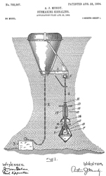
|
768567 Fig 2
Telephone transmitter and receiver
 |
Here's the block of 7 patents all granted on the same date with
sequential numbers:
768567
Submarine signaling,
Arthur
J Mundy,
Submarine
Signal Co, App: 1902-04-23, Pub: 1904-08-23, -
768568
Sound transmitter and receiver,
Arthur
J Mundy,
Submarine
Signal Co, App: 1902-04-23, Pub: 1904-08-23, -
768569
Telephone-transmitter,
Arthur
J Mundy,
Submarine
Signal Co, App: 1902-04-23, Pub: 1904-08-23, -
768570
Sound transmitter and receiver,
Arthur
J Mundy,
Submarine
Signal Co, App: 1902-04-23, Pub: 1904-08-23, -
768571
Sound transmitter and receiver,
Arthur
J Mundy,
Submarine
Signal Co, App: 1902-04-23, Pub: 1904-08-23, -
768572
Sound transmitter and receiver,
Arthur
J Mundy,
Submarine
Signal Co, App: 1902-04-23, Pub: 1904-08-23, -
768573
Submarine sound-direction finder,
Arthur
J Mundy,
Submarine
Signal Co, App: 1902-04-23, Pub: 1904-08-23, -
------------------------ end of Submarine Signal Co block of
hydrophone patents -----------------------

|
1378960
Method of and apparatus for detecting under-water
vibrations, Warren
Horton Joseph, Western
Electric 1921-05-24, -
|

|
1381640
Detecting underwater vibrations, Warren
Horton Joseph, Western
Electric, 1921-06-14, -
Carbon microphones 7 & 8 or 7 & 9 are fed to the
telephone receivers 11 and 16 and can be used to get a
rough bearing to the source of sound.
|
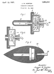
|
1624412
Submarine signaling, Joseph
W Horton, Western
Electric, Filed: 1919-10-31, W.W.I TOP SECRET, Pub:
1927-04-12, -
Fig 1: Carbon mike
Fig 2: Dynamic mike
Fig 3: Dynamic mike (to be used with an amplifier)
|
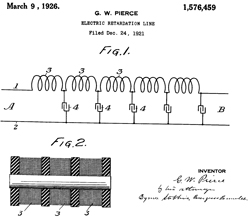
|
1576459
Electric retardation line, George
W Pierce, Submarine
Signal Co, App: 1921-12-24, Pub: 1926-03-09, -
"The present invention relates to electric retardation
lines, and more particularly to a retardation line for
introducing definite time retardation of electric currents
in a manner such that currents of a complex character will
be retarded in a rational and predeterminable way, with
out essential distortion, over a significant range of
frequencies. The present invention results in a
considerable extension over previous retardation lines the
range of frequencies for which the retardation time is
independent of frequency." - This
is a very important point. "The
present invention, however, is not limited to the
application of the retardation line herein disclosed, to
an electric compensator, ..."
I wonder if coax transmission lines were know then?
Ans: Yes (Wiki)
The Fenwick 1977 antenna patent is based on Time Delay
Beam Steering where the lobes are frequency
independent. Yet there are still many "phased array"
antenna systems where the main lobe modes with any change
in frequency, probably because they are much lower in cost
to make.
|
|
1682712
Electric compensator, George
W Pierce, Submarine
Signal Co, App: 1919-06-25, Pub: 1928-08-28, -
Although there is a "steering wheel" used to point the
SONAR beam, it is just an electrical switch, there is no
mechanical connection to a moving SONAR array.
For the switching scheme shown in Fig 2 to work the array
needs to be self similar, like a cylinder where the
elements are straight lines.
This is analogous to the motor driven Geionometer used on
the receive only Wullenweber antenna array (Wiki).
Since it dates from early in W.W.II the sound based
patents shown here predated it.
|

|
1893741
Arrangement for directional transmission and reception
with a plurality of oscillators, Hecht Heinrich, ELAC
Electroacustic GmbH, Priority: 1928-01-14, Pub:
1933-01-10, -
Fig 4 placement on the bottom of the sea (or on the bottom
of a harbor).
|
|
1969005
Apparatus for the directional transmission and reception
of wave energy, Hecht Heinrich, ELAC
Electroacustic GmbH, 1934-08-07, - |
|
1997974
Apparatus for the directional transmission or reception of
wave energy, Rudolph Wilhelm, ELAC
Electroacustic GmbH, 1934-10-23, -
|

|
1995708
Electrical compensator for the directional transmission or
reception of wave energy, Fischer
Fritz Alexander, ELAC
Electroacustic GmbH, App: 1929-11-21, Pub:
1935-03-26, -
|
|
2473974
Underwater sound detecting and indicating system, Schuck
Oscar Hugo, Navy,
App: 1944-05-18, W.W.II, Pub: 1949-06-21, - Hugo has a
number of SONAR patents.
Omni-directional 14 kHz transmit but rotating directional
receive beam. Spiral scan on CRT.
|
|
2582994
Underwater microphone, James
M Kendall, Geophysical
Research Corp, Priority: 1943-06-04, W.W.II, Pub:
1952-01-22, - seismic surveys or research
|

|
2592738
Electronically controlled low impedance phase shifting
device, Stanley
R Rich, Navy,
App: 1945-09-19, Pub: 1952-04-15, -
The U.S. BQR-2 & BQS-4 SONAR domes are a based on the
1929 German compensator.
The use of "phase shift" networks is a problem in that the
pattern is a function of frequency. Much better to
use time delay which can be frequency independent.
|
|
2597005
Method of calibrating microphones, James
M Kendall, Geophysical
Research Corp, Priority: 1943-06-04, W.W. II, Pub:
1952-05-20, -
also see patent 2582994 Underwater microphone,
|
|
2684449
Commutator tube, Stanley
R Rich, Jr
Edwin E Turner, Raytheon,
App: 1946-03-19, Pub: 1954-07-20, - for use with the SONAR
system of patent 2786193 below.
|

|
2703396
Underwater echo range and bearing apparatus, Stanley
R Rich, Navy,
App: 1944-11-11, TOP SECRET,
Pub: 1955-03-01, - The key benefit it reduced time to make
a 360 degree search.
Fig 1. TVG = Time Varied Gain. Scope shows spiral
pattern. Also see: SSQ-53A
Audio Analysis Patents 2418846 where the Tx and Rx
elements rotate at different speeds.
Fig 3 thin Nickel laminations with coil.
BQR-2 and/or BQS-4 SONAR?
|
|
2786193
Underwater sound system, Stanley
R Rich, Raytheon,
App: 1948-03-10, Pub: 1957-03-19, - no mechanical moving
parts. Uses commutator tube patent 2684449 above.
|
2138036
Compressional wave sender or receiver, Kunze
Willy, Submarine
Signal Co, 1938-11-29, - Quartz crystal, Rochelle-salt,
cited
by34 patents
2616223
Device for converting electrical energy into mechanical
oscillation energy, Jonker
Gerard Heinrich, 1952-11-04, - cited
by 23 patents.
2631271
Tubular
hydrophone, A.L. Thuras (New London, CT), Sec
of Navy, Mar 10, 1953, 367/168 - CRT-1
2973739
Underwater transducer, Nelson
N Estes, 1961-03-07, - for
actuating thereby acoustically sensitive mines or the like
submerged therein.
3255431
Hydrophone, Glenn
N Howatt, Gulton
Ind, 1966-06-07, - piezoelectric - looks like a
lolly-pop
3266011
Hydrophone, Massa
Frank, Dynamics
Corp of America, 1966-08-09, - low cost for sonobuoy
3659255
Hydrophone calibrator, Winfield James Trott, 1972-04-25, - 1 Hz
to 5 kHz, a pair of piezo electric cylinders in a pressure
vessel. uses static pressure change for calibration.
4965778 Helical
magnetostrictive core line hydrophone, David
E. Parker, Markay
Malootian, Secretary
Of The Navy, Oct 23, 1990 (21 year
delay), 367/168 -
Brush Development Co. Patents
Their early work with Piezoelectric
devices (Wiki)
was for microphones and speakers used in
air. But this was long after the Germans,
see SSQ-53A Ref 18.
1906758 Crystal and method of producing the same, Kjellgren
Bengt, Brush
Dev Co, May 2, 1933, 117/69,
117/68, 117/926, 252/1, 562/580 - Rochelle
salt - but the methods seem the same as used today for
silicon or any other crystal.
2105010
Piezoelectric
device, Baldwin
Sawyer Charles, Brush
Dev Co, Jan 11, 1938, 381/190,
310/331, 367/164, 601/2, 367/161, 381/173 - Rochelle salt disk or plate or
stacks or grids of them, mike or speaker
2126437
Apparatus for generating
electrical waves - tubes
2269403 Piezoelectric unit -
loudspeaker for use in air (for similar
loudspeaker see:
LS-685/U Crystal Loudspeaker)
2413462 Transducer, Massa
Frank, Brush
Dev Co, Filed: Jul 30, 1942, Pub: Dec 31, 1946, 367/157, 310/340, 381/190, 310/337, 310/362, 367/163 - early hydrophone (no
projector function)
2440903 Underwater
transducer, Massa
Frank, Brush
Dev Co, Filed: Jan 6, 1944, Pub: May 4, 1948, 367/160, 381/190, 381/163 - "piezoelectric and
magnetostrictive transducer devices adapted to
function underwater either as a microphone or as a
loudspeaker." 38
patents reference this one
3418624
Coaxially mounted line hydrophone, Frank
Massa, Dynamics
Corp of America, 1968-12-24, -
3489994
Line hydrophone, Frank
Massa, Dynamics
Corp of America, 1970-01-13, - Seismometer
The geophones used in Vietnam era outdoor
intrusion detectors are functionally seismometers. Hydrophones with good low frequency
response can also be used as seismometers. The MERMAID (Mobile
Earthquake Recording in Marine Areas
by Independent Divers - Earth
Scope Oceans) devices drift at a depth of about 1500 feet
to a mile and when they "hear" a P-wave (Wiki) they
surface, get GPS coordinates and use the Iridium satellite telephone
system to phone in the event. The hydrophone output has a
0.1 Hz high pass filter and is sampled at a 40 Hz rate.
Note P-waves are very useful for studying the interior structure
of the Earth. They are the first (Primary) wave from an
earthquake to reach a given location and so are the basis of
earthquake alarms (Seismometer)
Son-Of-MERMAID (A
tale about MERMAIDs) is also an ocean hydrophone that
works more like a sonobuoy. That's to say there's a float
with GPS that knows where it is and a 1,000 meter cable supports
a hydrophone. An on board recorder captures events that
appear to be P-wave events.
Note that this system does not detect S-waves (Wiki) and so
is lacking a lot of earthquake data, but it is a way to get some
data that covers 3/4 of the Earth (i.e. the oceans where there
is currently no data at all on earthquakes).
Hazeltine Hydrophone and
Retainer Assembly A22267-1
Found this on eBay but the photos and description were not at
all clear. It's a linear array of 6 hydrophones.
Let me know if you have any
information on this hydrophone assembly.
Box label (Fig 1):
Hydrophone and Retainer Assembly
1 ea.
NOAS 58-548C
Hazeltine Corp Mfg/Contr
A22267-1
A-IA-8X-6/60
Sub-Item 5
Sensitivity Minus _____ db |
6 EL SH HYD
(6 ELement Small Hydrophone HYDrophone?)
Cable can: 4" dia x 5-3/8" high
This is smaller than an A Size
sonobuoy (4-7/8").
Maybe fits inside an A-Size?
Hydro Cup: 2" OD x 5" high
Cup holds 5 hydrophones + cup-end hydrophone
for 6 total.
|
|
Fig 1 OEM Box
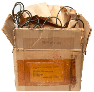
|
Fig 2 unknown total cable length.
No depth option, always the same.
 |
Fig 3 latch mechanism (not clear how it
works)
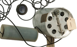 |
Looking for Hazeltine patent that might cover this, no luck, but
maybe related ideas like lines of hydrophones.
5132940
Current source preamplifier for hydrophone beamforming, James A. Culbert, Hazeltine Corp,
1992-07-21 - listening buoys
2891232
Hydrophone for directional listening buoy, Heinrich O Benecke,
1959-06-16 -
2898589
Hemispherical acoustic phase compensator, Abbott Frank Riley,
1959-08-04 - makes use of a miniature replica
3037185
Sonar apparatus and components, Gerhard H Dewitz, Cgs Lab Inc, 1962-05-29 -
"In one embodiment of this invention, which will be described
presently, a scanning system is provided which does not depend
upon mechanically moving parts for controlling the direction of
the transmitted beam or the direction of greatest sensitivity of
the receiving apparatus, and which permits continuous high speed
scanning over any desired area." i.e. beamforming
3064235
Audible broadband sonar monitor, Keith E Geren, 1962-11-13
- a broadband ( kHz to 100 kHz) hydrophone driven receiver with
special signal processing for hearing "single ping" sonar at an
unknown frequency
3116471
Radio sonobuoy system, Jesse J Coop, 1963-12-31
- directional sound receiving beam coupled with magnetic compass
do give directional information DIFAR
3281769 Transducer apparatus, Theodor F Hueter, Honeywell Inc, 1966-10-25
- probably for underwater locator beacon since "for use at extreme
depths."
3559160
Spatial surveying and target detection system, Bradshaw Burnham, US Secretary of Navy,
Filed: 1963-11-07, Pub: 1971-01-26 "10,000 hydrophones", tubes
SOSUS?
3903407
Method for correlating frequency-modulated signals, Bradshaw Burnham, US Secretary of Navy,
Filed: 1963-12-11, Pub: 1975-09-02 - photo-optical, SOSUS?
3905320
Low frequency homing system, William J Mueller, US Secretary of Navy,
1975-09-16 - homing system for torpedoes "The low frequency homing
system of this invention utilizes lines of hydrophones or
transducers spaced along the port and starboard sides, and along
the top and bottom sides of a torpedo."
2409632
Guiding means for self-propelled torpedoes, Robert W King, AT&T Corp, 1946-10-22
- active ultrasonic SONAR
4423494
Beam steerable sonar array, Kenneth W. Groves, John D. Lea, Sperry Corp, 1983-12-27 -
6088299
Vertical hydrophone array, Louis W. Erath, Phillip Sam Bull, Syntron Inc, 2000-07-11
- seismic exploration cable includes time delay elements:
"traveling wave antenna"
Roswell
Connection
While studying the MH370 disappearance
and search (March - April 2014) and in particular the 37.5 kHz ultrasonic
pings from the Cockpit Voice Recorder (Wiki:
CVR) and the Flight Data Recorder (Wiki:
FDR) generated by the Underwater Locator Beacon (Wiki:
ULB, Ultrasonics).
This lead to the SOFAR channel (Wiki) and
the thermocline (Wiki).
A way to determine the depth of the thermocline is to drop an
SSQ-36 (see SSQ-36) or other Bathythermograph
such as the SSXBT (Wiki:
BT). Note that the maximum depth of the SSQ-36 is 800
meters, not the center of the SOFAR channel which might be at 1000
meters, but low enough to be in the channel.
2587301 Method of sound transmission, Ewing
William M, (Wiki),
Us
Navy, Filed: Nov 16, 1945 (7 year
delay), Pub: Feb 26, 1952,
67/127
- "sound channel" , Fig 7 map showing listening
staations: Aleutian Islands, Kurie Islands, Marinas, Saipan
Islands & Midway. Explosion set for 675 fathoms.
2601245
Underwater
signaling device, Charles
F Bowersett, Filed: Jan 30, 1948, Pub: Jun 24, 1952, 181/142,
102/229, 181/125 -
contains explosives
2760180 Long range explosive sonobuoy, George
Sipkin, Filed: Oct 6, 1949, (7 year
delay), Pub: Aug 21, 1956, - explains sound channel - It's a buoy
with a hydrophone and when it hears a ship it drops an explosive
set to go off in the SOFAR channel. Shore based hydrophones
hear the explosion and can triangulate the location of the
explosion. A 10,000 mile range is expected. This
sounds like the same system of shore stations described for the
SOFAR bombs.
3517378
Underwater long-distance sound-detection system, Robert
E Barrett, Navy,
App: 1959-11-06, SECRET, Pub:
1970-06-23, - probably SOSUS (Crypto, Wiki) related -
transducer at about 2,000 feet deep detects sub. A relay
transducet at 4,000 feet deep (in the sound channel) relays the
sub detection to a shore station.
3483837
Streamlined missile device for location of submarines, Robert
E Peterson, 1969-12-16, - a streamlined missile attaches to
a sub using a magnet. A switch closed and a signal between
16 kHz and 24 kHz indicates the depth.
Cites:
|
297648
Marine Torpedo, J.H.L. Tuck, Submarine Monitor Co,
1884-04-29, - ?
|
|
1300062
Submarine signaling device, George
H Walker, 1919-04-08, - electromagnets attach to
sub and roll along it activating switches to signal
contact
|
|
1460175
Torpedo head, Joseph
A Rayder, 1923-06-26, - switch in nose to set of
explosives.
|
|
2397995
Submarine detector, Wikstrom
Arne, App: 1943-03-24, W.W.II, Pub: 1946-04-09, -
strong magnet attaches to sub which then signals an
attachment
|
|
2405990
Spotting submarines, John
T Beechlyn, Submarine
Signal Co, App: 1943-05-22, W.W. II, Pub:
1946-08-20, - a slavo is fired off the bow of a ship,
when they hit a sub a buoy is released and it jumps out
of the water.
|
|
2545179
Submarine marker with sonic signal generators, Voorhees
Vanderveer, Standard
Oil Co, 1951-03-13, - underwater benchmark
consisting of a heavy housing, batteries and a vibrator.
|
|
2656458
Compressional wave telemetering device, Joseph
M Johnston, Joseph
B Olsen, John
A Moulden, 1953-10-20, - Helmholtz
Resonator with diaphragm which by capacity change
FM modulates a radiosonde
transmitter. The resonator can be tuned to a low
(not specified) frequency.
|
|
2750794
Acoustisonde apparatus for measuring and recording
physical properties of the sea, George
W Downs, Navy, 1956-06-19, - "...conditions of the
sea such as pressure, temperature, turbidity, salinity,
and radioactivity are detected by submerged apparatus
and transmitted as sound through the water to receiving
and recording apparatus at the surface thereof. |
Cited by:
4448106
Method of identifying hard targets, Richard
D. Knapp, McDonnell
Douglas Corp, 1984-05-15, -
It turns out that a stock sonobuoy can not hear the 37.5 kHz ULB
since the highest frequency they can hear is 20 kHz (see DIFAR above). So a stock sonobuoy can
not be used to find the CVR or FDR. But all the information
about sound propagation in water is applicable to normal sonobuoy
operation.
Note that military passive SONAR (Wiki)
is designed to pick up the sounds generated by surface ships,
submarines and torpedos (maybe 10 Hz to 20 kHz), not aircraft
black boxes at 37 kHz. This frequency range does include a
lot of sea life so a sonar man needs to know what they sound like,
or his computer knows. If you rub your thumb and index
fingers together you generate an ultrasonic sound, like that used
by Bats, in the 30 kHz region but no
normal audio.
Maurice Ewing (Wiki)
who discovered the SOFAR channel (Wiki)
figured out that the speed of sound vs. depth would cause sound to
be "piped" if it was in the SOFAR channel rather than being
omnidirectional if not in the channel. He extrapolated that
idea to the atmosphere where the speed of sound vs altitude curve
has the same shape as the one for speed of sound vs depth in water
and so there should also be an atmospheric channel ( it turned out
to be at about 50,000 feet whereas the ocean channel is at about
1000 meters deep). By putting microphones (in the 1940s the
state of the art microphone technology was the Disk Microphone
(used by Orson Wells - Wiki),
or disk for short like we now say radio instead of Radio Receiver)
in the channel you can hear sounds from very very far away that
you can not hear any other way. Disk microphones are called
"spring
microphones" on eBay. For example rocket launches or
atomic bomb testing.
Richard
Muller Physics Lecture 11 - Waves 1 (Richard
A. Muller - Sound Channel)
Smithsonian National Air and Space Museum: Ask
an Expert: The Roswell Incident, Apr 22, 2011 -
Wiki: Sofar bomb - Naval
Airborne Ordnance NAVPERS 10826-A (Aircraft Reference book 17)
describes the SOFAR bomb on pages 195 & 196 as "a 4-pound
cylinder casing carrying the explosive, and a head which enables
the operator to select one of the six possible depth settings
between 1,500 and 4,000 feet." There is a Pacific ocean
map showing receiving stations at Point Arena and Point Sur on
the California coast and at Kaneone in the Hawaiian islands.
In the book Principles of Underwater Sound by Robert J. Urick (Reference 10) there is an example of the
SOFAR bomb on page 415.
Communication
Problem: In the sofar method of aviation rescue, a downed
aviator drops a 4-lb explosive charge set to detonate on the
axis of the deep sound channel. How far away can the
detonation be heard by a nondirectional hydrophone, also located
on the axis of the deep sound channel, at a location of moderate
shipping in sea state 3?
Solution: (detailed description of calculation) 4,000 miles.
Then I watched the UC Berkeley Physics 10 - Lecture
11: - Waves I (YouTube,
Text)
by Richard Muller (Amazon).
It turns out that the Project Mogul (Wiki 1947
- 1949) used the bulk of a CRT-1
sonobuoy. They replaced the hydrophone with a string
of "Disk Microphones" that was 657 feel long. He also
mentions SOSUS and "Hunt for Red
October" in passing. The SOFAR bomb was used by W.W. II
pilots downed in the ocean. They would throw this hollow
metal sphere (SOFAR bomb aka: SOFAR Sphere (Wiki)) into
the water and it would sink. After about 5 minutes it would
reach about 1000 meters depth and implode. The implosion had
the energy of about 2 pounds of TNT. The shore based SOFAR
stations would note the time of arrival and triangulate the
location of the implosion. Later the Signals (underwater
sound) Mk 22 Mods 0 and 1 were developed to work with the shore
stations. If an enemy captured one of these SOFAR bombs and
cut it open it would be very unlikely that they could determine
what it was or how it was used.
When Project Mogul flight No. 4 crashed outside Roswell the Air
Force reported that "flying disks had been recovered" from the
wreakage, but the local paper reported it as a "RAAF
Captures Flying Saucer". Note the change from
plural because there were a large number of disk microphones to
singular Flying Saucer".
See my Western Electric 387W Disk
Microphone web page for an example of a disk
microphone. Note eBay search term "Spring Microphone".
The Wiki page Roswell_UFO_incident
- has an image
from the Roswell Daily Record, July 8, 1947. The main
headline is: "RAAF Captures Flying Saucer On Ranch in Roswell
Region". The subheading is "No Details of Flying Disk Are
Revealed".
The problem I have with the "flying disk" idea is that those
spring microphones are extremely heavy and because of that would
never be flown below a balloon. So either there is some
unknown to me "disk microphone" or another explanation for "flying
disks".
The Roswell Daily Record, July 9, 1947 (roswelldailyrecord9jul1947.jpg):
Harassed Rancher who Located 'saucer' Sorry He Told
About It
W. W. Brazel, 48, Lincoln county rancher living 30 miles south
east of Corona, today told his story of finding what the army at
first described as a flying disk, but the publicity which
attended his find caused him to add that if he ever found
anything else short of a bomb he sure wasn't going to say
anything about it.
Brazel was brought there late yesterday by W.E. Witmore, of
radio station KGFL, had his picture taken and gave an interview
to the Record and Jason Kellahin, sent here from the Albuquerque
bureau of the Associated Press to cover the story. The
picture he possed for was sent out over AP telephone wire
sending machine specially set up in the Record office by R.D.
Adir, AP wire chief sent here from Albuqueruue for the sole
purpose of getting out his picture and that of sheriff George
Wilcox, to whom Brazel originally gave the information of his
find.
Brazel related that on June 14 he and an 9-year old son, Vernon
were about 7 or 8 miles from the ranch house of the J.B. Foster
rance, which he operates, when they came upon a large area of
bright wreckage made up on rubber strips, tinfoil, a rather
tough paper and sticks.
At the time Brazel was in a hurry to get his round madea nd he
did not pay much attention to it. But he did remark about
what he had seen and on July 4 he, his wife, Vernon, and
a daughter Betty, age 14, went back to the spot and
gathered up quite a bit of the debris.
The next day he first heard about the flying disks, and he
wondered if what he had found might be the remnants of one of
these.
Monday he came to town to sell some wool and while here he went
to see sheriff George Wilcox and "whispered kinda confidential
like" that he might have found a flying disk.
Wilcox got in touch with the Roswell Army Air Field and Maj.
Jesse A. Marcel and a man in plain clothes accompanied him home,
where they picked up the rest of the pieces of the "disk" and
went to his home to try to reconstruct it.
According to Brazel they simply could not reconstruct it at all.
They tried to make a kite out of it, but could not do that and
could not find any way to put it back together so that it would
fit.
Then Major Marcel brought it to Roswell and that was the last he
heard of it until the story broke that he had found a flying
disk.
Brazel said that he did not see it fall from the sky and did not
see it before it was torn up, so he did not know the size or
shape it might have been, but he thought it might have been
about as large as a table top. The balloon which held it up, if
that was how it worked, must have been about 12 feet long, he
felt, measuring the distance by the size of the room in which he
sat. The rubber was smoky gray in color and scattered over an
area about 200 yards in diameter.
When the debris was gathered up the tinfoil, paper, tape, and
sticks made a bundle about three feet long and 7 or 8 inches
thick, while the rubber made a bundle about 18 or 20 inches long
and about 8 inches thick. In all, he estimated, the entire lot
would have weighed maybe five pounds. (See: Radar
Reflectors)
There was no sign of any metal in the area which might have been
used for an engine and no sign of any propellers of any kind,
although at least one paper fin had been glued onto some of the
tinfoil.
There were no words to be found anywhere on the instrument,
although there were letters on some of the parts. Considerable
scotch tape and some tape with flowers printed upon it had been
used in the construction.
No strings or wire were to be found but there were some eyelets
in the paper to indicate that some sort of attachment may have
been used.
Brazel said that he had previously found two weather balloons on
the ranch, but that what he found this time did not in any way
resemble either of these.
"I am sure what I found was not any weather observation
balloon," he said. "But if I find anything else besides a bomb
they are going to have a hard time getting me to say anything
about it.
This web page was started because of the connection to Vietnam era
seismic detectors (outdoor intrusion alarms).
But I still have not determined which sonobuoy was the source for
the 2-3/4" diameter cylindrical components of the GSQ-160, if you know please tell me.
In the official Air Force book "The Roswell Report - Fact vs.
Fiction in the New Mexico Desert - Headquarters United States Air
Force - 1995 - ISBN 0-16-048023-X (free on line as roswell.pdf)
- 993 pages see attachment 32, "Report of Findings on Balloon
Research", chapter Project MOGUL, pdf-Pg 303 that describes the
underwater sound channel and the idea by Dr. Maurice Ewing (Wiki) that
there might also be a sound channel in the atmosphere and how to
exploit that idea as Project Mogul (Wiki).
A Google Patents search on inassignee:"Gen
Mills Inc" balloon will turn up many patents related
to the new type balloon good for high altitude
2526719 Balloon construction, Winzen
Otto C, Gen
Mills Inc, Apr 2, 1948 - key is replacing
rubberized fabric with polyethylene (Wiki)
2492800 Fast rising sounding balloon, Isom
Langley W, Aug 16, 1948 - key non elastic
material.
2767940
Balloon with strengthening elements, Donald F Melton, General Mills Inc, Filed:
1953-11-04 -
2767941
Seam for gored balloons, Frederick J Gegner, Alan A Reid, General Mills Inc, Filed:
1953-11-04 -
In the book An Ocean in Common: American Naval Officers,
Scientists, and the Ocean Environment (Ref
4) they mention that the sound channel in the Atlantic ocean
is 4,000 feet but in the Pacific it's at 2,500 feet. (page 173).
June 2018: In the book UFO Crash at Roswell: The Genesis of a
Modern Myth edited by Benson
Saler - There is a chapter on the ML-307 Radar Reflector.
The Project Mogul balloon flights (Wiki)
are described as being run as an unclassified program to
develop constant altitude balloons, not the actual flights
with disk microphones. Project Genetrix (Wiki)
balloons carried 600 lb. cameras. Ran 1955 to 1958.
2666601
Constant altitude balloon, William F Huch, General Mills Inc, Filed:
1952-02-15, Pub: 1954-01-19
2606443
Exploration of troposphere stratification, George W Gilman, Bell Labs, Filed:
1946-06-14 - shows existence of sound channel, although not called
that
3070335
Automatic lift augmentation for balloons , Leland S Bohl, William F Huch, Edward P Ney, John R Winckler,
Secretary of the Navy, Filed: 1959-08-04, Pub:
1962-12-25 - has the feel of Skyhook balloon (Wiki)
flies at 100,000' (harder to shoot down)
3369774
Balloon envelope structure, Jr Arthur D Struble,
Filed: 1961-08-02 -
also see: Radiosonde and New UFO
Information April 2014
2021 Sep - While
learning about the equipment used to receive and process the DIFAR
signal from the SQQ-53A sonobuoy, which it turns
out is almost if not totally identical to a passive sonar, I
started looking into passive and active SONAR (Wiki). I
hit a roadblock. Even the Wiki SONAR web page shows neither
the frequency v. time waterfall display nor the bearing angle v.
time waterfall display not any of the waterfall displays that
combine those two.
Also there are two very different frequency bands. Classic
active SONAR uses a "ping" frequency that's in the audio range
since very high power levels are needed for long range. This
is analogous to RADAR where the units designed for search use
lower frequencies (Wiki: SURTASS)
and units designed for tracking or homing use higher frequencies
because smaller antennas work better at higher frequencies.
What's called "broadband SONAR" operates at ultrasonic
frequencies. So on a sub there's the classical SONAR
operator and the Broadband SONAR operator.
When the MH370 went down Sonobuoys could not be used to hear the
ELB ping at 37.5 kHz because that's above the frequency range of
classical SONAR and above the sonobuoy frequency range. But
I'm guessing that a submarine could hear the ULB ping if they were
close enough on the Broadband SONAR. For example see the projects at Extreme
SONAR. 1 to 470 kHz passive SONAR, Projects at In-Depth
Engineering: BLQ-10, BQQ-10, SQQ-89
Processing of Data from SONAR Systems, Vol III, Morton Kanefsky,
Allen Levesque, Peter Schultheiss & Franz Tuteur, of Dunham
Laboratory, Yale University, General Dynamics/Electric Boat, 1965
(AD0476591.pdf)
- a very technical analysis of a hydrophone array of 40 elements
at 2 foot spacing relating to optimal signal processing when
there's an interfering signal or unknown noise levels. It
has the feel of the Fenwick time delay beam steering patent and
the antenna system with both main beam steering and null steering.
A Fresh Look at "Broadband" Passive Sonar Processing, Robert
Zarnich, (ADA367050.pdf#page=100)
Black Box for ships
6706966
Hardened voyage data recorder, L3
Communications Corp, 2004-03-16 - a black box for
ships. Based on the 1974 the Safety of Life at Sea (SOLAS)
Convention. - Patent
Citations (89) -
Unknown Sonobuoy - What is it?
There are many similarities with the CRT-1, but . . .
It looks like mid 1960s (date code, TO-3 power transistor in power
supply, 1xx and 3xx tubes).
Someone has scratched SONOR on one of the sheet metal covers with
an arrow pointing down. This implies it's an active pinging
unit rather than a passive listening only unit.
That is reinforced by the large space for batteries.
This is not mine. Photos and information supplied by
Michael, VK4ZKT
UnKS Fig 1

|
UnKS Fig 2 Tubes may be 12AT7,
not low voltage like in the CRT-1.
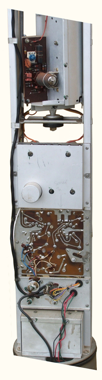
|
UnKS Fig 3
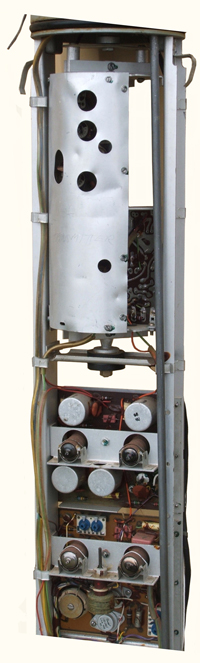
|
UnKS Fig 4
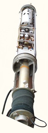
|
Unknown Sonobuoy No. 2
I received a couple of emails from John B. who lives in
Greece. He has sent a number of photographs of a sonobuoy
that makes use of both tubes and solid state devices.
Fig 1

|
Fig 2
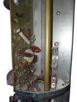 |
Fig 3
 |
Fig 4
 |
Fig 5
 |
Fig 6
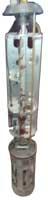 |
Fig 7
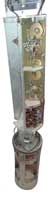 |
Fig 8
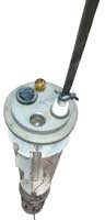 |
Fig 9 Chesapeake Instrument Corp.
Shadyside, MD
 |
Fig 10 Hydrophone
Mod. SB 154C
Auditory
Capacities in Fish.pdf
5cm dia x 1.5cm thk
barium titanate
-89 decibels (re 1 volt per microbar of sound pressure)
and a frequency response essentially flat from 50 cps.
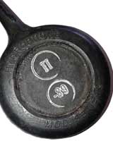 |
Fig 11
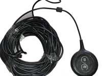 |
Fig 12
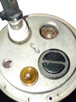 |
Fig 13
 |
Fig 14
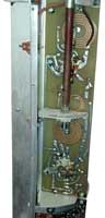 |
Fig 15
 |
Fig 16
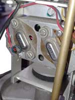 |
Fig 17
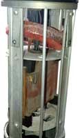 |
Fig 18
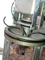 |
Fig 19
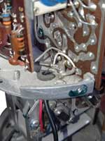 |
Fig 20
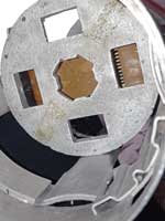 |
Fig 21
 |
Fig 22
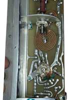 |
Fig 23
 |
Fig 24
 |
Fig 25
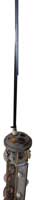 |
Underwater Communications
Patents for underwater communications
2530528
Phase comparator for underwater signaling, John
G Kreer, Bell
Labs, App: 1944-11-01, Pub: 1950-11-21, - involves balanced
modulators and SONAR bearings
2798902
System and method for underwater communication, Kursman
Daniel Richard, Sigmund
P Rosen, 1957-07-09, - single-sideband (Wiki)
Suppressed-carrier transmission and reception, balanced modulator
& filter, audio 250 Hz to 3 kHz, 8.1 kHz oscillator/carrier
frequency. 6 Watt Tx has range of 2,000 yards.
2958039
Delay line time compressor (Deltic), Victor
C Anderson, University
of California, 1960-10-25, - used in patent 4203164
3076174
Method and apparatus to enable swimmers to converse under water, Walter
N Wainwright, Russell
I Mason, 1963-01-29, - all audio frequency
3164800
Underwater telephony, John
T Kroenert, Navy, 1965-01-05, - bal mod & filter, SSB,
8.1 kHz oscillator/carrier.
3181116
Underwater telephone system, William
F Gordon, 1965-04-27, 367/132 455/40 367/124 455/73 -
10kHz balanced carrier
3218607
Underwater telephone, Charles
R Brock, Reginald
J Cyr, Bendix,
1965-11-16, - aprox. 50 kHz carrier
3263207
Transistor underwater telephone system, Herbert
L West, Francis
E Huff, Navy, 1966-07-26, 367/132 330/298 455/40
331/116R - may look like flashlight
3267414
Portable underwater communication unit, Kritz
Jack, Janus Prod, 1966-08-16, - similar to a flashlight.
3277429
Communication system, Ralph
G Lucas, 1966-10-04, - radio buoy & submerged ultrasonic
transducer
3337841
Underwater telephone, Walter
N Wainwright, Russell
I Mason, Jr
Victor Savchuk, Stanley
L Ehrlich, Navy,
1967-08-22, - modular system, for free swimmers,
3495209
Underwater communications system, Homer
A Engle, 1970-02-10, -
3789353
Diver communication system, E Hunter,
D Smith,
Navy,
1974-01-29, - binaural output to facilitate the localization of
sender. balanced modulator SSB system.
3848226
High capacity underwater acoustic release, G Perez, AMF Inc
(American Machine & Foundry), 1974-11-12, - cited
by 26 patents.
4039999
Communication system, John
Weston, 1977-08-02, - uses angle or FM modulation for noise
rediction
4203164
Secure sonar communication system, Robert
D. Isaak, William E. Klund, Woodrow H. Littrell, Richard G.
Stephenson, Navy,
App: 1961-03-06, TOP SECRET,
Pub: 1980-05-13, -
Tones: 1446, 1450 & 1454 break: 1442 Hz. 27 dB
process gain, Citations
& Cited
by.
Makes use of Pseudorandom noise (Wiki)
- this may have been one of the first, if not the first, use of
PN noise in a crypto
patent and it probably why the 19 year delay in granting
the patent. The emitted signal is called Low Probability of
Intercept (Wiki).
Range increment switch for: 0.1, 1 or 10 miles. Three
CRTs, one is related to range,
"While use of underwater sound and detection systems
are not new as a means for communicating between marine and
submarine vehicles, their limitations are well known and in many
instances very disconcerting. For example, the underwater
telephone was limited to a transmission range of approximately
10,000 yards, echo ranging sonars had a maximum effective range
of 2000 to 3000 yards, and passive detection of cavitating
vehicles was only successful as far as 10,000 to 20,000 yards.
In addition, such systems were extremely susceptible to enemy
detection and their data transmission rate was slow and often
resulted in obtaining inaccurate information."
"Although the systems of the prior art mentioned above and the
subject invention both propagate acoustical energy through an
aqueous medium for communication purposes, their similarity ends
there. The present invention, for instance, enables messages and
data to be exchanged between submerged submarines separated by
distances as great as two hundred miles. Further more, in the
process of establishing communication, the range distances and
bearing between submarines may be measured and displayed with an
accuracy limited only by the knowledge of the speed of sound in
the operating area. Detection security is feasible through
techniques utilizing a relatively low source spectrum level made
possible by broadband signal projection, a highly directional
receiving hydrophone and transducer array, and the processing
gain derived by cross-correlation of the received signal with a
local replica. Insonification of a minimum ocean area results
from directional transmission and use of the oceanographic
convergence zone phenomenon which, likewise, improves security
from detection by other than the intended communication target
vessel. The initial acquisition on the readout display itself
constitutes positive friend or foe identification which, of
course, provides considerable additional security. Also, since
the signal transmission may be varied between a few seconds and
a few minutes as necessary to meet given operational
requirements, and inasmuch as the signal energy is noise-like in
character and is distributed over approximately a one half
octave frequency band, the probability of detection by the enemy
is relatively small. Moreover, because a local time-varying
replica is employed for the correlation process, a very high
degree of cryptographic security is inherent."
4227479
Submarine communications system, Morton
Gertler, Lester
F. Whicker, Thomas
Gibbons, Navy,
App: 1962-08-07, (SECRET for 18 years) Pub: 1980-10-14, - TV
camera, TV antenna,, VLF antenna, LF antenna (this was prior to
satellites).4336537
Bi-directional underwater communication system, Fredrick
G. Strickland, 1982-06-22, - tethered to radio buoy
4418404
Single-sideband acoustic telemetry, Alan
Gordon, Stanley
J. Watson, Steven
J. Cowen, Gerald
Mackelburg, Brett
D. Castile, Navy,
1983-11-29, -
6856578
Underwater alert system, Daniel
J. Magine, Kevin
D. Kaschke, Feb 15, 2005, 367/134 - Ocean Technology
Systems Diver Recall System DRS-100?
3867715
Underwater communications system, Fred G
Geil, Navy,
1975-02-18, - sub to sub, reversed time order, WQC or UQC:
underwater telephone,
4203164
Secure sonar communication system, Robert
D. Isaak, William
E. Klund, Woodrow
H. Littrell, Richard
G. Stephenson, Navy,
App: 1961-03-06, TOP SECRET, Pub: 1980-05-13, -
6118732
Secure marine communication system, John
Lamar Worzel, Alan
Berman, Navy,
App: 1959-02-12, TOP SECRET, Pub: 2000-09-12, -
7218574
High range rate signaling, Maurice
D. Green, Teledyne
Benthos, 2007-05-15, - backs out range rate
BQC-1 Underwater Telephone (Wiki: Gertude)
Battery powered portable unit in sub escape trunk. (SEATALK
frequencies?)
YouTube: Sub Brief: Whiteboard: AN/BQC-1
Underwater Telephone 5:06 - Patreon, Aaron
Amick, SubBrief.com,
MIL-S-15232 - SONAR SET AN/BQC-1 ( )
Voice Mode:
500 yard (1500 feet) range.
Single Side Band (USB), not the double sideband in the early
patents below.
8.3 kHz carrier.
Beacon Mode:
20,000 Yard (11 mile) range.
24.26 kHz ping once every 30 seconds.
BQC-1B & C additional homing tone: 9.58 kHz.
WQC-2 Underwater Telephone
Wired into sub or surface ship control room. More
power. 8.0875 kHz carrier frequency.
UQC-1 was replaced by the WQC-2. (SSQ-53A Ref 1, pg 142)
8kHz to 10.5kHz see JANUS
paper on Telesonar below.
Communication Buoy "Float the
Buoy"
4227479
Submarine communications system, Morton
Gertler, Lester
F. Whicker, Thomas
Gibbons, Navy,
App: 1962-08-07, (SECRET for
18 years) Pub: 1980-10-14, - TV camera, TV antenna,, VLF
antenna, LF antenna (this was prior to satellites).
STANAG 4748
is a digital protocol that has a range up to 28 km (17 miles).
Bit
Allocation table, 002
Underwater AIS (Wiki,
this is the maritime version of ADSB).
Underwater
Acoustic Communication and Modem-Based Navigation Aids -
Telesonar
Signaling and Seaweb Underwater Wireless Networks, J.A.
Rice, Oct 2000 - 8kHz to 10.5kHz (compatible with WQC-2.
Acoustic release (Wiki)
A device holds instrumentation or crab (Wiki) or
Lobster (Wiki)
traps down until it receives an specific acoustic signal at which
point it releases the package to float to the surface.
They are similar to aircraft bomb racks in that heavy loads can be
held securely and released when desired. This typically
involves linkages.
3848226
High capacity underwater acoustic release, G Perez, AMF Inc
(American Machine & Foundry), 1974-11-12, - cited
by 26 patents.
Submarine Missile Hanger
The Regulus Missile (Wiki)
seems related to this patent by the Martin Co.

|
2735391
Warship Weapons System, Including Aircraft Storing and
Launching Arrangement, H.H. Buschers,
Glenn
L Martin Co, 1956-02-21, -
2792599
Seal, Gantschnigg
Gottfried Karl, Herbert
H Buschers, Glenn
L Martin Co, 1957-05-21, -
|
Submerged Signal Ejector
(SSE) 3" Port
aka: Submerged Signal and Decoy Ejectors (SSDE)(Wiki)
Maritime.org - 12-4-01
Submerged Signal Ejectors - 6" internal diameter:
These are similar to 100mm diameter torpedo tubes and probably are
located in torpedo rooms. These tubes can be used to launch
various devices that fit the 100mm (4") tube.
Countermeasures, emergency beacons, signal flares, small explosive
charges and probably a Bathythermograph (would require a way to
handle the trailing wire) . . .
T-347/SRT
Submarine Rescue buoy that transmits SOS SUB SUNK SOS is about
3-1/4" dia x 40-1/2" long and can be launched using the SSE.
It appears this is more of a standard than just for subs.
Aircraft also have a 3" dia. launch tube.
3" Launch Tube devices top to
bottom:
T-347/SRT
Buoy, Radio Transmitting -
launched from submarine
Vaisala RD93 GPS
Dropsonde - launched from airplane
SUS:
Signal Underwater Sound -
launched from airplane
Sippican Ocean Systems SSXBT Model ST-1 Bathythermograph -launched from
submarine

Ref 8 mentions a 3" signal/decoy ejector
(pg 69 photo of Bathythermograph & its terminal) that can be
used for the Submarine
Launched One-way Transmitter (SLOT)(pg 70). In the
Glossary (pg 308) "usually 3-inch".
So are there two
different small launch tubes, i.e. 3" and 4" or has one of
these become a standard? let me
know
Patents related to
this have been moved to the Signal Underwater Sound (SUS)
Mk 84 web page Patents section.
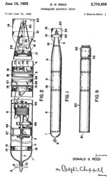
|
2710458
Underwater acoustic
decoy, Reed
Donald G, Sec of Navy, Filed:
Jun 14, 1945 (10.0 year delay), Pub: Jun
14, 1955, 434/6,
114/20.1,
367/1,
434/25
- passive SONAR training device
Fig 1: either 3x32" or 4x43", most likley 3x32"
Fig 9: either 3x24 or 4x32"
This may or may not be launched from a sub.
|

|
2981927
Underwater sound
transmitter, Vaughn
G Mckenney, Sec of Navy, Filed: Apr
4, 1946 (15 year delay: SECRET),
Pub: Apr 25, 1961, 367/1,
455/18,
114/20.1,
360/6
- returns SONAR pings at same frequency but offset in
time (very similar to RADAR countermeasures). see Radar Warning
Receiver
Fig 1 shows a length/diameter ratio of 11.5, so if 3"
dia then length is 34", if dia is 4" then length is 46".
Since a yard or meter shows up as a practical length
then I'd assume this is a 3 x 34" device.
maybe launched from the SSE 3" port?
Mentions: 2793589
Buoyancy
control device, Atchley
Raymond D, Filed: May 3, 1944,
(13 year delay), Pub: May 28, 1957, 102/414
-
|
|
3379273
Powerful sound impulse generation methods and apparatus, Stephen
V Chelminski, Bolt
Technology, 1968-04-23, - the "airgun" mentioned by
AAron in Sub Brief: Analysis: Seismic
Airgun - used for geology of the ocean bottom.
Has the look and feel of the Gamewell
Diaphone Air Horn used at fire stations to call
firemen and as a Fog Horn.
|

|
5003515
Submarine emergency
communication transmitter, Albert
S. Will, Frank
C. McLean, Sylvan
Wolf, Samuel
H. Kauffman, John
C. Hetzler, Jr., Charles
A. Lewis, George
E. Maxim, Secretary
Of The Navy, Filed: May 28, 1964,
(27 year delay) Pub: Mar 26, 1991, 367/131,
367/145
-
Image flipped so that it's oriented as if in the
water. There are 7 drop bombs which are released
by explosive bolts and they explode after 20 seconds so
that their depth will be controlled (probably within the
sound channel (see Roswell
Connection above). If the sink rate was the
same as the Mk IX depth charge (15 fps) then after 20
seconds it would be down to 300 feet which is too
shallow to get into the SOFAR Channel (Wiki).
I suspect the time delay is really much longer to that
the drop bombs get into the SOFAR Channel.
The timing of the drop bomb release translated into one
of a number of coded messages.
The length/diameter ratio is very small so will not help
to determine its dimensions.
See other Albert Will patents
|
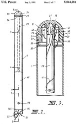
|
5044281
Submarine flare
with vertical attitude determination, Peter
Ramsay, Brian
W. Whiffen, Gerald
M. Bushnell, Victor
Nanut, Robert
C. Czigledy, Robert
J. Swinton, Maxwell
J. Coxhead, Timothy
R. Clarke, Australia,
Sep 3, 1991, 102/340,
102/224,
102/351,
102/357,
102/354
-
The length/diameter ratio is 12.67, so: 3" x 38" or 4" x
57", seems to indicate it's 3 x 38".
|
UAV
UAV (Wiki) that can be launched from sonobuoy tube.
6056237
Sonotube compatible unmanned aerial vehicle and system, Richard
L. K. Woodland, 2000-05-02, - cited by 276 other patents
Global Hawk
While learning about the AMT-6 Dropsonde which is 5"
dia x 21-1/8" long I check to see if that was a standard
sonobuoy size. It is not. But the F size is about 5" x
12". The Global Hawk (Wiki,
NCAR/NOAA,
Dropsonde)
drops a smaller unit (1-3/4" x 12"). I suspect sonobuoys
could be dropped either by making them the same size or by using
a different dispenser. The existing dispenser holds three
dozen dropsondes and feeds then to a single launch tube.
3093808 Air-dropped miniature
sonobuoy, Gimber
George A, Scarcelli
Albert F, Tatnall
George J, Secretary
of the Navy , Jun 11,
1963, 367/4, 441/33, 441/25, 343/709, 455/99 - cited
by 31; Prior art sonobuoys were
3' long, 5" diameter and weighed 16 to
20 pounds limiting aircraft time on
station and had a max depth of about
50'. This one is 15" long, about
3" dia and weighs about 5 pounds with
a max depth of 300'. also see 3047259
Speed brake retarding mechanism for an
air-dropped store, George
J Tatnall, Albert
F Scarcelli, Navy,
1962-07-31, - Note this may be
compatible with the common 3" launch
system (the same as the Submerged
Signal Ejector)
4721961
Submarine detection system, Henri
G. Busignies (Wiki),
Louis
A. DeRosa, ITT
Avionics, App: 1959-11-03, TOP SECRET,
Pub: 1988-01-26, - lightening generates
a vertically polarized pulse that's
reflected from subs.
Command Activated Sonobuoy (CAS)
5452262
mentions "Another modulation scheme uses a DTMF (dual tone,
multiple frequency) encoder to modulate an AM transmitter at
UHF. This allows the use of inexpensive "touch tone' telephone
technology. Thus, using a key pad encoder and decoder circuit
board, sixteen unique decoded outputs can be obtained by
pressing only one keypad button per command. Combinations of two
and three keypad digits may be used to further expand the
command set, with increased complexity at the decoder
end." Limited to Line-Of-Sight (LOS) or about 10 miles for
sonobuoys.
3344420
Data collection system, Melvin
W Arsove, Raytheon,
1967-09-26, -
The sonobuoy has a 1N21 mixer diode in a microwave circuit
responsive to the search radar in a P-3. When a Command is
given to a specific sonobuoy over the UHF CAS link data in
modulated on the 1N21 diode by an audio frequency. The
aircraft PPI display shows a sonobuoy icon and numerical data
from the sonobuoy,
3676780
Digital frequency generator for coded interrogation, George
W Niemann, Charles
N Shannon, Navy,
App: 1966-06-09, SECRET, Pub: 1972-07-11, -
"A command control sonobuoy system is provided in
which a large number of buoys are commanded on a single
frequency from a remote position. A single radio frequency
carrier signal is modulated with selected two tone signals from
a plurality of discrete tones derived from digital elements upon
the receipt of instructions from an operator or a computer."
Uses a 1.6384 MHz crystal divided by 512 = 3200 Hz.
3731262
Time mark-numeral generator system, R Blake,
Navy,
1973-05-01, - uses a sonobuoy that includes a magnetic tape
recorder.
"The present invention relates to generator systems
and more particularly to a time mark-numeral generator system
which performs the major function of timing and identification.
Time marks and numerals are permanently exposed on recording
film so as to indicate the buoy number, time of day, the day,
and the month that corresponding data on the film was recorded
in the buoy at some remote point.
There frequently arise occasions when it is important to record
over extended periods of time various sounds and noises which
arise below the surface of the sea. This information would be
particularly important during the case of a war to give an
indication of submarine activity, or the information may be used
to indicate the movement of schools of fish, the location of
geodetic explosions, or even the movement of thermal tides. The
usual procedure for obtaining this type of information is
through the use of either passive sonar or listening equipment
located within a moored sonor buoy. The buoys continuously
record the sea noise on some form of film or magnetic tape
usually in a frequency band in the neighborhood of 10 to 300
cycles per second. When it is necessary to retrieve the recorded
information, an interrogation signal is sent to the buoy which
then plays back the recorded data to some remote station.
Certain procedures proposed for analyzing the data require a
knowledge of the time of day signals were recorded in the buoy.
For convenient application of these procedures, it is necessary
to have a time scale corresponding to recording time written in
the margin of the recording film. However, there are no timing
signals available in the transmitted RF signal from the buoy to
the remote station which can be used to deter mine recording
time. Therefore, the construction of a time scale must be based
on the time playback is started and the ratio of playback to
recording speed, so experience from past attempts to write time
numerals on the film manually indicated that an automatic system
was needed."
Maybe this was a precursor to SOSUS (Wiki)?
Or maybe testing locations for SOSUS hydrophones?
3772639
Sonobuoy mooring unit, R Snyder,
Navy,
1973-11-13, - (same time frame as 3731262 & not at all
standard sonobuoy practice. maybe testing locations for
SOSUS hydrophones?
3783441
Air launched, wire guided torpedo, Z Slawsky,
Navy,
App:1965-06-30, SECRET, Pub: 1974-01-01, -
"A submarine detecting and tracking system which
ultilizes sonouoys to track both a target submarine and a guided
torpedo. The sonobuoy signals are received and processed on a
surface vessel or aircraft and the torpedo is guided by remote
control to intercept the target submarine." Torpedo leave a buoy
on the surface and a wire connects buoy and torpedo.
Cites
2 patents, Cited
by 16 patents.
4660182
Programmable multichannel sonobuoy transmitter, Albert
M. Bates, Wayne
H. Sandford, Jr., Michael
T. Junod, Navy,
1987-04-21, - 145.375 (Chan 57)
Sonobuoy Training
3649735
Transmission System, William
K Coburn, Richard
E Hillger, Navy,
App:, SECRET, Pub: 1972-03-14, - simulates up to 9 sonobuoys and
transmits on a single antenna to nearby aircraft. The
location of the buoys and sub can be set as well and the speed
and bearing of the sub. The signal amplitude to each of
the sonobuoys is attenuated to match the range to the sub.
Sea State noises are included. 162.25 to 173.5 Mhz. range
where 5 adjacent channels of the possible 16 channels can be
selected.
4436049
Simulator for testing sonobuoys,
Louis E. Ante, Richard
A. Lindquist, Eugene
R. Roeschlein, Navy,
1984-03-13, - a floating barge with a 2-way winch can
simulate wave motions.
Related
Aircraft
CRT-1 Sonobuoy
Magnetics -
Magnetostriction,
Sound Bug
Helmholtz coil -
Helmholtz Resonator
& Tuning Forks
Torpedoes, Mines, Depth Charges
Submarines
GEO_ID - TRC-3, PEWS, USQ-42, Turd
GSQ154 - All GSQ-154
GSQ160 - Frequency Disconnect -GSQ-160,
USQ-46, TS-2963, PP-6446 -
TCw - cylindrical
module pinouts.
GSS26 - AN/GSS-26 minimal info
Intrusion Alarm Patents
USQ_Rx - Igloo White, USQ-42, USQ-46
details,
PSR-1 - now on it's own page (July 2007)
Modular Outdoor Intrusion Sensors
(REMBASS?)
Astronomy - UFOs -
Richard
Muller Physics Lecture 11 - Waves 1
P-3C Systems
I lived in Mountain View, California for some decades
and Moffett Field was the base for P-3 aircraft.
NASA operated a flying telescope and a U-2 there as well as a
giant wind tunnel among many wind tunnels of all kinds.
Just looking up the systems listed for the Update II.
Navy.mil: Standard
Aircraft Characteristics, P-3C Update II.pdf , 12 pages,
1984 -
Coms
Data Terminal
|
ACQ-5A
|
Teletypewriter
|
AGC-8
|
Intercom
|
AIC-22(V)1
|
UHF
|
ARC143B
|
HF
|
ARC-161
|
Emerg. Trans
|
PRT-5
|
Crash Locator
|
URT-26(V)
|
VHF Comm Group
|
618N-3/A
|
Armament
|
Nav
True Airspeed
|
A24G-9
|
Central Repeater
|
AM-4923/A
|
Flight Director System
|
AJN-15
|
Altimeter
|
APN-194(V)
|
Navigation Set, Radar
|
APN-227
|
RAWS
|
APQ-107
|
UHF DF
|
ARA-50
|
LF-DF
|
ARN-83
|
Omega
|
ARN-99(V)1
|
TACAN
|
ARN-118(V)
|
AFCS
|
ASW-31A
|
Horiz. Situation Ind
|
ID-1540/A
|
Periscope Sextant
|
MS28011-7
|
OTPI Receiver
|
R1651/ARA
|
Sonobuoy Reference Set
|
ARS-3
|
VHF Navigation Group
|
VIR-31
|
Inertial Nav System
|
LTN-72
|
|
Non-Acoustical Sensor Data
ESM Set
|
ALQ-78A
|
Radar
|
APS-115B
|
IFF
|
APX-72
|
SIF
|
APX-76A(V)
|
| SAD |
ASA-64A
|
| Compensator |
ASA-65(V)2
|
| Compensator |
ASA-65(V)2 |
| MAD |
ASQ-81(V)2
|
| IRDS |
AAS-36
|
| IRDS VIdeo REc Grp |
OA-8962/ASH
|
Disp Grp, Tact Aux (TADS)
|
OD-159A
|
|
Acoustical Sensor Data
Sonar Comp Rec Grp
(Triple Vernier)
|
AQA-7A(V)6/7
|
| Sono Recorder Sys |
AQH-4(V)2
|
Sonobuoy Rcvr Sys
|
ARR-72(V)
|
| CASS (Modified) |
ASA-76A
|
| Bathythermograph |
SSQ-36/RO-308
|
| Sea Noise Meter |
ID-1872A
|
| IACS |
OV-78/A
|
|
Data Processing/Display
Tact Disp
|
ASA-66
|
Radar Scan Conv
|
ASA-69
|
Tact Dsip Grp
|
ASA-70
|
Avn Unit Comp
|
ASQ-114(V)4
|
Data Anal Proc Grp
|
AYA-8B
|
Synchro Conv
|
CV-2461A/A
|
Time Code Gen
|
TD-900A/AS
|
Dig Dta Rec Rep
|
ASH-33
|
|
ACQ-5 Data Link
This is a data link system based on the aircraft HF-1, HF-2 or
UHF-2 radios. Uses Navy Tactical Data Systems serial
protocol which includes symbology.
PP-6140/ACQ-5 Power Supply
C-7790/ACQ-5 Control Monitor - modem control
CV-2528/ACQ-5 Data Terminal Set Converter-Control - 26-bit serial
modem in normal use: Clock Select=Master, Control=Operate, then
other troubleshooting controls are disabled.
Communications Interface No. 2 - converts 30-bit parallel computer
words into 26-bit serial data
Used with Link 11 (Wiki: MIL-STD-6011)
and KG-40 (Crypto
Museum)crypto.
AIC-22 Aviation Inter Communications
Aircraft intercom using headsets.
The prior system was the AIC-18. There were complaints of
the radios interfering with the intercom and an investigation
showed that using fiber optics would decrease the problem.
AM-3364/AIC-22(V) Interconnecting Box Amplifier
ARC-143 UHF Radio
Control head
Tranceiver
ARC-161 HF Radio
C-9245/ARC-161 Control Box
RT-1000/ARC-161 Receiver Transmitter
AM-6561/ARC-161 RF Amplifier
CU-2070/ARC Antenna Coupler
works with TSEC/KY-75 Remote Control Unit
PRT-5
Floating buoy that transmits on 8.364 MHz and 243.0 MHz.
1/4 Watt output power on both bands and a 3 day battery
capacity. Looks like a replacement for the Gibson Girl. A 9 foot ling
telescoping HF antenna will not be very efficient on HF (0.076
wavelength).
AQA-7 Sonar Computer Recorder Group
(Triple Vernier)
"That system was the AQA-7 that "burned" the recorded data on
paper. In it's original form it was call the "Jezebel" and we'd
often call the acoustic operators "Jez" even after it was long
gone from the aircraft. It would scroll like a fax machine and at
the end of the mission, the paper would be turned in to the
debriefing gang for reconstruction. One positive thing was the
paper was an immediate visible replay of the information gained by
the sonobuoys and the operators would also write and do
computations on the paper itself. Plus an operator could cut off
the paper and remove from the machine and review back in time
while on the mission to maybe see if contact was missed. The
negative was the nasty smell this machine produced!!!!!!!
Initially the buoys were "Lofar", or basically the buoy would
detect a sound and give the operator a circle around the buoy and
it would take multiple buoys to localize to a small area to
search. "Difar" buoys, which provide sound
recordings, but more importantly, direction from the buoy were the
next important tool to be developed and replaced Lofar. Two or
three buoys with lines pointing to a noise source and there it is
where those lines intersect.
The USN went away from the AQA-7 when the P-3C Update III came on
line in the mid 1980s. The acoustic processing system was now all
computerized, Lofar buoys were a thing of the past. The new system
was called the UYS-1, and the big and probably final upgrade to
that system was introduction "CHEX" or channel expansion, allowing
the aircrews to have 99 channel capabilities for buoy channel
numbers of buoys instead of only 32 (see Channels
above). Now, all the data is recorded on tapes that had to be
replayed on ground based computer systems to review the mission
and compare with operator notes. (Operators could not do this
in-flight). That system is what is featured in the Hickory
Aviation Museum's P-3C (See below), with plasma
panels to enter data and manipulate the buoys. When flying, the
operator on the right was the lead, he'd usually do the Difar
work, which was passive only, just listening for noise. The other
operator was usually in training and would help and also do the
Dicass, or active buoys should they be authorized. Dicass would
provide a range and bearing from buoy to target with burst of
energy, just like sonar.. I flew on aircraft with both systems,
and a lot comes down to the quality of the operator and numerous
other factors such as oceanographic conditions, and of course, the
target itself. Hope that answers the question, if not, let me
know., I had 3k+ hours flying P-3C?s." . . . . Brian Harrison
"I concur with what Bill said for the most part. The AQA-7
operators, SS1 and SS2, didn't provide circles. They would provide
frequency of the signal, its signal strength, time of detection
and loss of signal. Based on the signal strengths, the TACCO could
draw circles around the buoys on his display to help localize the
target. The greater the signal strength, the smaller the circle.
Where the circles intersected, if they did, could provide possible
target locations. That was only useful if the signal was direct
path (nearby the buoy), but not if the signal was actually from a
convergence Zone (CZ) (much farther away). The TACCO would use
tactics to determine between the two. The tactics would include
more Lofar buoys and/or some Difar buoys." Brian's brother.
4736199
Method of selectively displaying data, Victor
J. Chadwick, Ronald
W. Barnes, BAE
Systems, 1988-04-05, -
WO2001098796
Acoustic surveillance system with signature and bearing data
display, John
J. Molini, Warren
C. Hollis, Sung Hong,
Lockheed-Martin,
2001-12-27- has examples of various waterfall displays.
Fig 1 LOFAR waterfall with frequency on
X-axis.
You can get this from an omnidirectional sonobuoy

|
Fig 2 Side by Side LOFAR waterfall and
Bearing Time Recording (BTR) waterfall
 |
Fig 5 Composite acoustic data display
Top display Frequency waterfall. (frequencies 0 to 2400 at
bottom)
Left display Bearing waterfall (bearings 0 to 360 at
right).
Lower right (main) display Frequency-Bearing display
 |
Fig 6 Correlogram Frequency-Bearing display
 |
Fig 7 Pictorial of the frequency/bearing
area of Fig 5
|
|
BQC-1 Underwater Telephone (Wiki: Gertude)
YouTube: Sub Brief: Whiteboard: AN/BQC-1 Underwater Telephone
5:06 - Patreon, Aaron
Amick, SubBrief.com,
"Float the Buoy" 4227479
Submarine communications system, Morton
Gertler, Lester
F. Whicker, Thomas
Gibbons, Navy,
App: 1962-08-07, (SECRET for
18 years) Pub: 1980-10-14, - TV camera, TV antenna,, VLF
antenna, LF antenna (this was prior to satellites).
Submarine Laser Communications (SLC)
4995101
Secure two-way communications with submerged submarines, Paul
J. Titterton, Frederick
Martin, Dan
J. Radecki, Robert
W. Cotterman, GTE
(GD),
1991-02-19, - cited by 33 patents.
Pushbroom is a type of scanning (Wiki)
not a program name.
Modern digital communications require wide bandwidths which are
hard to come by using radio transmissions and so are moving to
modulating light (either in an optical fiber or directly through
the air, like in the Starlink satellite-to-satellite
links.
I think SOSUS developed the various waterfall displays but in a
crude electromechanical way that would be too heavy and bulky
for use on aircraft. But the next generation equipment
would fit on aircraft. The first generation SOSUS worked
with paper plotters (probably using the same paper as the Western
Union DeskFax machine).
3611277
Sensitive hydrophone, Max N
Yoder, Navy,
1971-10-05, - laser interferometery
3893061
Underwater acoustic detection system, Zaka
I Slawsky, Wayne
Dee Wilson, Navy,
1975-07-01, - This is really a transponder that sends out a ping
when it detects something interesting.
4115753
Fiber optic acoustic array, Peter
Shajenko, Navy,
1978-09-19, -
Frederick Hunt (Wiki)
in charge of the Harvard Underwater Sound Laboratory and came up
with the word SONAR. He developed a technique called the
Bearing Deviation Indicator (BDI). The following patent is
cited my many other patents.
2166991
Direction finding system, Guanella
Gustave, Radio
Patents, 1939-07-25, - This "Big Ears" was a system based on
sound (prior to RADAR) to detect the ultimate weapon of that time,
the high altitude bomber.
Here are some patents by Frederick Hunt:
2666192
Apparatus for determining the direction of underwater targets, Frederick
V Hunt, Schuck
Oscar Hugo, Charles
R Rutherford, Hathaway
Jarrett Lewis, Jr
Arthur Nelson Butz, App: 1944-07-27, W.W.II, Pub:
1954-01-12, - this is for an active 20 kHz "Searchlight" type
SONAR and improves the bearing accuracy. The CRT trace time
starts at the bottom center and when a return arrives it deflects
the spot to the right if the target return is to the right.
To get the bearing the searchlight is turned to the right until
the spot is centered. This is a SONAR patent.
2595791
Transducer, Frederick
V Hunt, Navy,
App: 1946-04-05, W.W.II, Pub: 1952-05-06, - magnetostrictive
(moved to the CRT-1 sonobuoy web page)
Missile Launch Patents
6164179
Submarine deployable vertical launch spar buoy, Martin
Buffman, Navy,
2000-12-26, - "Fixed air support missiles (FASM) have been
developed for multiple missions. The fixed air Support missile
is a class of Small missile which can be used against airborne
targets Such as helicopters, can be deployed to provide aerial
Surveillance, or can be used for ground Support missions. These
missiles are relatively Small and cheap. They have not been
deployed on Submarines because of launching considerations."
Cites:
| 3158062
Missile container and launcher, Feiler |
describes a launching tube for a
missile, which launching tube is designed to protect the
missile while it is being transported to its launch
Site. The Feiler launching tube is further designed to
be anchored in an upright position So that the missile
stored within can be launched vertically. |
4586421
Underwater weapon systems,
|
illustrates yet another vertically
oriented, underwater launch tube for a missile. The
launch tube comprises an elongate outer container which
is buried or partially buried in the Seabed in an
upright position. The container uses devices at its
bottom end for removing Sand or Silt and an auger for
boring a hole in the Seabed or a rotary stirrer. The
missile is housed within an inner container which is
telescopically arranged within the outer container. |
| 5092222
Float up system for submarine launched missiles, Lynch |
illustrates a float-up launching System
for launching missiles from Submerged Submarines or
other Submerged launchers which utilizes a lightweight
rigid cylindrical tube telescoped over the missile while
Stored in the launcher. On launching, the tube is
extended forward of the missile by a gas generator to
form a floatation chamber which creates extra buoyancy
forward of the missile center of gravity. This lifts the
missile nose upward to the water Surface allowing
ignition of the missile booster motors and launch of the
missile. |
| 5076192
Unmanned submarine for air rocket, Tegel & Wenzel |
illustrates an unmanned Submarine
launching System which is guided to the Surface of the
water in order to launch an air rocket contained therein
and which is provided in its walls with closeable
openings for the discharge of the rocket recoil gases
into the Surrounding water to conduct the impinging
recoil gases of a launched air rocket directly out of
the Submarine. |
4854260
Configuration of discharge tubes, ejection tubes or
receptacles in submarines, Woidich & Toobe
|
illustrates a configuration in which
bodies such as torpedoes can be held in an additional
container inside a torpedo tube in a Submarine. The
container is in the manner of an interior tube. The
annular space between the torpedo and its tube is used
to hold damping elements, which are located individually
or over the entire structure of the torpedo, and the
annular Space is kept free of water by means of Sealing
elements. Another damping element is positioned in the
rear portion of the container in the torpedo tube. |
5542333
Undersea vehicle ejection from capsules, Hagelberg &
Allardt
|
illustrates an Under Sea Vehicle Storage
and Ejection System which includes a capsule having a
cavity for storing and launching a vehicle. The capsule
has an opening at one end for passage of the vehicle
therethrough. A closure member is adapted to be mated
with the housing at the opening to seal the cavity. A
rocket unit is incorporated within the capsule to remove
the closure member at launch. The closure member
includes a sealing arrangement for withstanding the
hydrostatic pressure when the system is in the under sea
environment of use and block the entry of sea water into
the cavity. The rocket unit, when ignited, rapidly
builds up pressure within the capsule to a level
exceeding the external hydrostatic pressure on the
cover, thereby removing the cover So that the vehicle
may be launched. |
Movies
Bombshell: The Hedy Lamarr Story - IMDB - Claims
that the Navy used her invention on DIFAR sonobuoys in the RF
link back to the airplane. The reference cited is:
http://www.rism.com/atribute.htm#sonobuoy
Which no longer is on line and archive.org does not have a copy.
But that's a false claim since the link back to the aircraft is
not encrypted. and doesn't need to be. There's no enemy to hear
the transmission. Even today with satellites it's
questionable if there's any value in encrypting the link.

|
2413066
Torpedo control by multiple channel selector, Ellison
S Purington, Navy, App: 1935-11-06, SECRET, Pub:
1946-12-24, uses either one of two RF frequencies or
one of two audio modulation tones for Left or Right
signal. |
|
2292387
Secret communication system, Markey
Hedy Kiesler, Antheil
George, App: 1941-06-10, granted the next year,
1942-08-11, -
This is for a secure way to use radio remote control for a
torpedo.
While
67 patents cite this one, Lamarr & Purington do
not cite 2413066 above.
Note this patent was granted in about a year and during
W.W.II, not held like the patent above until after W.W.II.
which goes to say it was not considered a secret or
anything to protect.
|
Books & References
Also see: Aircraft
Reference books, Submarine
References, Torpedo
Reference Books,
Ref
1.
Naval Institute Guide
to the Ships and Aircraft of the U.S. Fleet, 18th Edition
(2005) by Norman Polmar
Ref 2.
The Ears of Air ASW: A
history of U.S. Navy Sonobuoys (2008) - Holler, Horbach &
McEachem
Ref 3.Scientists Against
Time, James Phinney Baxter, 3rd ed, 1946 - 1952 (
Wiki)
Ref 4.
An Ocean in
Common: American Naval Officers, Scientists, and the Ocean
Environment, Gary E. Weir, 2001, ISBN: 1-58544-114-7
Ref 5.
Design and
Construction of Crystal Transducers, NDRC Summary Report Vol
12, 1946 (407 pages) - University of California Division of War
Research [UCDWR]
Ref 6.
The Evolution of the Sonobuoy from
World War II to the Cold War, Holler, Jan 2014.
Ref 7. Sonobuoy History
from a UK Perspective: RAE Farnborough's Role in Airborne
Anti-Submarine Warfare, Clive Radley, 2016 -Chapter 4: The first
operational Sonobuoy, the AN/CRT-1,
used by the USA and the UK in World War 2.
Ref 8. Submarine (Tom Clancy's
Military Reference), 2003 - mentions 3" signal/decoy ejector (pg
69), Submarine Launched Oneway Transmitter (SLOT) also uses the
3" launch tube (pg 70)
Ref 9.
History of
Communications-Electronics in
the United States Navy,
L. S. Howeth, 1963 -
U.S. Early Radio History
- Ch 26: Dev of Underwater Sound and Detection Equipment, pg 297
Ref 10. Principles of
Underwater Sound by Robert J. Urick, 3rd ed, Hardcover ISBN:
9780932146625
Ref 11. Wiring Vietnam:
The Electronic Wall, Anthony J. Tambini,2007 (
wiring_vietnam.pdf)-
some mention of sonobuoys (Exhibits at: Patuxent River Naval Air
Museum & USS Hornet Museum).P-2 used (
pg
69) typo? ". The P2V was selected for this mission and other
special operations missions because of its long history of
successfully deploying antisubmarine detection devices, primarily
the magnetic anomaly detector. " should be primarily the Sonobuoy.
Ref 12.
History
of Ultra Electronics Maritime Systems Inc. - The History of
Sonobuoys - "from October 1942 to the war’s end in 1945, the U.S.
Navy had ordered 150,000 sonobuoys and 7,500 sonobuoy
receivers". An NDRC document actually states 160,000 so
reality is 150/160k.
Ref 13.
Batcats: The
United States Air Force 553rd Reconnaissance Wing in Southeast
Asia by Sikora & Westin, 2003 -
Ref 14.
EC-47:
Acoubuoy,
Spikebuoy, Muscle Shoals and Igloo White.pdf by Chris
Jeppeson 1999 -
Ref 15. Photo 10-26-45
Acme news: Arthur Gremer, design engineer; Francis Burger,
supervising engineer; George Rogers, chief engineer; Mark Grant,
design engineer. Announced to public around October 1945.
Ref
16. History of Communications-Electronics in the
United States Navy, 1963 (
html,
pdf)
Ch XXVI Development of Underwater Sound and Detection
Equipment (html)
Ch XXXI The Navy and the Patent Situation (html) -
W.W. I
XXXIX SONAR (html)
Ref
17. Probing The Oceans For Submarines -- A History of the
AN/SQS-26 Long-Range, Echo-Ranging Sonar (
a538018.pdf)
266 pgs
1. Introduction
2. History
3. Launching Program
4. Full Scale Experimentation & Development
5. Prototype Testing
6. Supporting R&D
7. Rubber Dome Window
8. Equip Ops & Tactical Employment
9. Fleet Performance
10 Conclusions
11. End Notes
App A: Event Chronology
App B: Personnel by employer
Index
Looking for patents based on names mentioned in Ref
17.
2434469
Pressure-proof reproducer, William
A Myers, App: 1944-07-01, Pub: 1948-01-13, -
2537052
Tuning means for ultra high frequency signal generators, Andrew
V Haeff, Charles
B Smith, Robert
H Mellen, App: 1945-08-30, Pub: 1951-01-09, -
2563829
Cable seal, James
W Fitzgerald, Burton
G Hurdle, Carlton
L Morse, App: 1946-04-17, Pub: 1951-08-14, -
2694868
Echo repeater, Edwin
M Mcmillan, William
A Myers, App: 1943-08-03, Pub: 1954-11-23, -
3209314
Sound beacon, William
A Myers, Vaughn
G Mckenney, App: 1944-08-09, (SECRET
for 21 YEARS), Pub: 1965-09-28, -
3229245
Echo ranging display system, Burton
G Hurdle, Jr
Robert J Mackey, 1966-01-11, -
3246289
Resonant underwater hydrodynamic acoustic projector, Robert
H Mellen, 1966-04-12, -
3307142
Three-color echo ranging display, Harold
J Doebler, 1967-02-28,
3403374
Underwater hydrodynamic acoustic projector, Robert
H Mellen, Berman
Robert, Kenneth
L Moothart, Navy, 1968-09-24, -
4473896
Tactical Expendable Device, Harrison
T. Loeser, Harold
J. Doebler, Navy, 1984-09-25, -
5526323
Method and apparatus for interpretation of sonar signals, Robert
M. Chapman, GD,
App: 1965-09-28, (SECRET 31 YEARS)
Pub: 1996-06-11
5911172
Retractable underwater turret, Kyrill
V. Korolenko, Navy,
1999-06-08, -
6052335
Multiple-frequency sonar system, Kyrill
V. Korolenko, Navy,
2000-04-18, -
6229761
Estimating ship velocity through the water and over the ground,
Kyrill
V. Korolenko, Henry
Ralph D'Amelia, Henry
Robert D'Amelia, Navy, 2001-05-08, -
6868768
Surf zone mine clearance and assault system, Thomas
J. Gieseke, Kyrill
V. Korolenko, 2005-03-22, -
7940602
Real-time system and method of underwater depth discrepancy
detection, recordation and alarm notification, Kyrill
V. Korolenko, Navy,2011-05-10,
-
Ref
18. Hitler's Naval War, Cajus Bekker, 1971 - Around 1939 the
German Subs had pretty much the same problems that the U.S. had
starting in 1942. Torpedoes that ran deep, Magnetic
exploders that did not work, contact exploders that did not
work. Haven't yet seen circular running mentioned.
Ref
19. US Naval Weapons, Norman Friedman, 1983 (no copyright
notice) - Excellent information not in other books about how
decisions were made.
1. Guns (surface fire)
2. Fleet air defense before 1945
3. Underwater ordnance
4. Fleet are defense after 1945
5. Air-to-air weapons - See China Lake
6. Surface-to-air missiles
Appendidces: Guns, Fire Control Systems, Gun Mounts, Armor
Penetration, Airborne Radars, Sonars, Sonobuoys, Torpedoes,
Mines, Depth Charges, ASW Projectors, ASW Missiles, Guided
Missile Launching Systems, Surface-to-air Missiles, Bombs,
Nuclear Weapons, Air-to-Surface Missiles, Surface-to-Surface
missiles.
Ref 21. Pushing
Horizon: Seventy-Five Years of High Stakes Science, Ivan Amato,
1998 -
Ref
20,
Ref 22. Principles and Applications of
Underwater Sound, Originally Issued as Summary Technical Report of
Division 6, NDRC, Vol. 7, 1946, Reprinted...1968 (
pdf
321 pages) (
Print on Demand)
[at the time I ordered the print on demand book there was no free
on line copy. Maybe ordering the POD book freed it up?]
Part 1: Basic Principles of Underwater Sound
Part 2: Echo Ranging
Part 3: Listening
Ref
23. Naval War College Newport Papers 16; The Third Battle,
Innovation in the U.S. Navy's silent Cold War struggle with Soviet
Submarines, Owen R. Cote Jr, 2003
This is an excellent overview of the cold war ASW
approach by aircraft, surface ships and other submarines.
The USS Nautilus (SSN-571) had the machinery anchored to the
hull and so generated a large amount of noise. That led to
a new class of subs using "rafts" to isolate machinery and
dampened flexible tubing to move water in or out to lower the
acoustic signature of our subs.
1. From Holland to the Second Battle (end of W.W.II), the first
50 years
2. Phase 1: German Type XXI & early cold war - SOFAR
channel,
3. Phase 2: ASW & the two Nuclear Revolutions, 1950 - 1960 -
BQR-2 (Wiki),
BQR-4 (Wiki),
p32:CRT-1,
SSQ-2 (JPROC),
LOFAR
QHB sonar: scanning, 25 khz, 19" trans, 1,800 yds @ 20 knots
SQS-4 sonar: 15 khz, 5' array, 8,000 yds (DASH, QH-50)
SQS-23 sonar: 5 khz, 8' array, 10,000 yds
SQS-26 sonar (Wiki):
3.5 khz, 11 - 40 miles
HENs (Wiki: Hotel,
Echo,
November)
4. Phase 3: ASW and the Happy Time, 1960-1980
P-3 Orion (Wiki)
SOSUS
(Wiki) LOFAR,
LAMPS (see: AM-6536/ALR-54
LAMPS Radar Warning Receiver Front-end)
5. Phase 4: ASW & accoustic Parity, 1980-1990
"Because the Akulas did not produce powerful,
continuous, narrowband tonals, transient tonals often provided
the best initial detection opportunities at long range."
SURTASS (Wiki)
6. Forth Battle? Subs & ASW after the cold war
Ref
24. Aircraft and Submarines: The Story of the Invention,
Development, and Present-Day Uses of War's Newest Weapons, Willis
J. Abbot, 1918, 567pgs (
pdf)
Ref
25. Underwater Acoustics and its Applications. A
Historical Review. L & I Bjorno, 1999 (
pdf)
Ref
26. UoTX:
A
Guide to the Maurice Ewing Papers, 1912, 1925-1974 -
Ref
27. The Acquisition of Sonobuoys for the U.S. Navy, May
1976, 10 pgs,
a033812.pdf
- AQA-7 then AQA-9, SSQ-53 & SSQ-50 (then SSQ-62).
Ref
28.
AN/AQA
to AN/AQS - Equipment Listing -
Ref
29. Technologies for Sonar Processing, 11 pgs, (
19-04-South.pdf)
- examples of Time-Frequency and Time-Bearing plots.
LOFAR display: Y-axis newest time at top, X-axis
frequency, i.e. a Waterfall display.
Bearing Time Recording: Y-axis newest time at top, X-axis
bearing, i.e. another kind of Waterfall display.
"Before 1985, the sonar images produced by the signal processors
were printed to thermal hard-copy paper and then analyzed.
Each data tape generated about 1,000 sheets of hard-copy paper,
or more than 100,000 sheets for a single SSBN submarine mission.
Each image was printed on dry silver paper, which was quite
expensive in the quantities required."
Authors: Hugh M. South, David C. Cronin, Samuel L. Gordon,
Timothy P. Magani. - no patents by any of them
Ref
30. Naval SONAR, 1953, NAVPERS 10884
Ch 12 Sound-Range and Depth Recorders -
electrochemical wet paper feed roll stored in vapor-tight
tank. 2-speed paper advance motor and 2-speed left-right
stylus motor.
Ch 13 Submarine Listening Equipment - JP-1, JP-2 & JP-3
manually trained hydrophone,
Ch 17 SONAR Training Equipment: QFA-6 Attack Teacher - made by
Sangamo Electric Co. because 2 electric meter mechanisms were
used to move mirrors to position a spot of light on a
screen. The meters respond to E * I *COS(phase) which
matches the needed math for position plots. (I=ships speed,
E=COS(heading from East)
Ref
31. FAS:
ES310
Introduction to Naval Weapons Engineering Course Syllabus -
Under Water Acoustics & SONAR:
Introduction,
Enviornment,
ASW
Systems (Bearing Time History), Sonobuoys: DICASS, DIFAR,
VLAD
Ref
32.
Approved
Navy Training System Plan for the Navy Consolidated Sonobuoys
N88-NTSP-A-50-8910B/A, September 1998 -
The sonobuoys discussed in this NTSP are all A-size:
length 36 inches, diameter 4 7/8 inches. The sonobuoy weight
varies by manufacturer and buoy type, but will not exceed 39
pounds.
The BT, DIFAR, LOFAR, DICASS, VLAD, and DLC sonobuoys are used
in conjunction with the on-board systems of the P-3C, SH-2G, and
SH-60B/F aircraft.
The P-3C Update III, SH-60B Upgrade, SH-2G Upgrade and SH-60F
Upgrade are potential recipients of the ADAR sonobuoy.
The AN/SSQ-110 EER sonobuoy will operate with the P-3C Update
III to form the EER System. The AN/SSQ-110A EER sonobuoy will
operate with the P-3C Update III to form the EER and Improved
EER Systems, respectively. The SH-60B Upgrade, SH-2G Upgrade,
and the SH-60F Upgrade are potential recipients of the EER
sonobuoy.
SSQ-36 Bathythermograph
SSQ-53D/E Low Frequency Analysis and Recording (LOFAR)
SSQ-62B/C/D/E Directional Command Activated Sonobuoy System
(DICASS)
SSQ-77B Vertical Line Array DIFAR (VLAD)
SSQ-86 Data Link Communications (DLC)
SSQ-101 Air Deployable Active Receiver (ADAR)
SSQ-110/A Extended Echo Ranging (EER)
Technical Manuals
TM
|
Title
|
Format
|
| NAVAIR 28-SSQ-500-1 |
Sonobuoy Instruction Manual |
Hard copy |
| NAVAIR 28-SSQ-500-4 |
Basic Introduction to Air ASW Sensors |
CD-ROM |
| NAVAIR 28-SSQ-500-4A |
Basic Introduction to Air ASW Sensors
(Confidential Supplement) |
CD-ROM |
| NAVAIR 11-1-107 |
SUS Technical Manual |
Hard copy |
| NAVAIRINST 4010.3A |
Sonobuoy Inventory Cord Report, Control
& Disposition |
CD-ROM |
| NWP 3-20.5 |
P-3 TACMAN |
Hard copy |
| NAVAIR 01-75PA-75 |
P-3 A/B/C Airborne Weapons, Storage,
Loading Manual |
Hard copy |
| NWP 3-21.64 |
SH-60F TACMAN |
Hard copy |
| NAVAIR H60BB-LWS-000 |
SH-60B Airborne Weapons, Storage, Loading
Manual |
Hard copy |
| NWP 3-21.63 |
SH-60B/LAMPS MKIII TACMAN |
Hard copy |
| NWP 55-2-SH2/LAMPS MKI |
SH-2G TACMAN |
Hard copy |
Ref
33.
RP33
Fleet Oceanographic and Acoustic Reference Manual - 1999,
234 pgs,
Ref
34.
NASA
Technical Memorandum 85727, Review of Underwater Acoustic
Systems and Methods for Locating Objects Lost at Sea, Nov. 1983,
-
Development Spec. DuKane Model N15A234: 10 kHz pulse
12.5ms every 1.4 seconds. 8 ea 1450 Mercury batteries, 240 Hours
operating life (10 days), 2.340" dia x 7" long.
Photos:
Fig 1. ACR EPIRB
Fig 2 SUS Mk 59 Mod 5 Explosive Wt. 1.90 lbs, Total Wt. 4.80
lbs.
Fig 3 TDRSS tracking method
Fig 4 North Atlantic Ocean-depth profile
Fig 5 Down-looking sonar 30 deg beam
Fig 6. DuKane Model N15F210B FAA approved underwater sound
source
Fig 7 Burnet Model 590 FAA approved underwater sound source
Fig 8 Dukane N15M210 commercial version of naval Mk 87 Mod 0
with optional mounting bracket.
Fig 9 DuKane recovery aids used on early NASA missions
Fig 10 DuKane N15A217 long range Appolo unit w/bracket.
Fig 11 DuKane N15A234 severe environmental conditions
Fig 12 DuKane N15M210 delayed turnon timing device in end cap
Fig 13 Deep submersible (SCRAB) to 6,000'
Fig 14 Navy "Deep Drone"
Fig 15 Search transceiver/receiver block diagram. spread
spectrum Tx 9062 & 11.875 kHz.
Fig 16 Underwater transponder/transmitter block diagram
Fig 17 model of underwater depressor transducer vehicle
Fig 18 Fixed beam, towed transducer platform using NRL type
depressor (Rx @ 30 - 40 kHz & 9 - 12 kHz)
Fig 19 48-crystal beam forming underwater platform @ 10 kHz
Fig 20 Proposed concept for Fig 19
Ref
35. The Naby's Best-Kept Secret: is IUSS Becoming a Lost
Art?, D.M. Maskell, 2001 (DTIC:
ADA401150.pdf)
-
Ref
36.
History
of the Anti-Submarine Measures Division of the Tenth Fleet,
7 Dec 1981, 137pgs - depth charges, IN early 1941 SONAR was blind
when a sub got within a few hundred yards of a ship with SONAR
because the pattern was mostly horizontal. "One phase of
anti-submarine measures which later made a decisive contribution
to success in 1943 was practically non-existent at the close of
1941. This was naval anti-submarine aviation. The decisive
importance of naval aviation in an anti-submarine war seems not to
have been recognized prior to the outbreak of hostilities.
Fortunately its importance was recognized even later by the enemy.
" "The development of the sono-buoy* aircraft searchlights*
rockets* and the Mark 24 mine all occurred after 1941." "The use
of Army planes and personnel reporting as Sea Frontier Commands,
but not under control of CominCh, led to an intolerable
administrative situation whose liquidation was one of the main
objectives when TENTH Fleet was created in 1943." "The Mark
I sono-buoy was first dropped from a blimp on 3 April and was in
production by June 1942." Sep 1943 German GNAT acoustic homing
torpedo is deployed. The FIR countermeasure "singing saw"
worked, nullifying the GNAT. A chronology is on pdf page 120
covering 27 June 1941 to 12 June 1945.
Ref
37. The Age of Orion: The Lockheed P-3 Story, David Reade,
1998, 223 pgs - pg.18: "The AQA-3A JEZEBEL long range (passive)
acoustic signal processor/recorder system and its associated
ASA-20 JULIE "Explosive" echo-locating system." The AQA-3
appears to have the same front panel as the AQA-1, but slightly
different top just behind the panel.
Ref
38.Submarine Torpedo Tactics: An American
History Illustrated Edition by Edward Monroe Jones &
Shawn S. Roderick, 2014, 232 pgs -
Ref
39. A Brief History of U.S. Navy Torpedo Development, E.W.
Jolie, 1978 (
HNSA.htm)
Ref
40. Subband Energy Detection in Passive Array Processing,
Bono, Shapo, McCarty & Bethel, (
ADA405484.pdf)
Ref
41.
Sea
shadow (
Wiki,
HMB-1)
-
The
Polaroid Concept (
Sonar One Step Camera,
Ultrasonic) -
Ref
42.
F-117A
of The Seas: Lockheed Skunk Work's Sonar-Invisible Submarine
-
Ref
43.
ASDIC and SONAR in the
RCN -
Ref
44. Meeting the Submarine Challenge: A Short History of the
Naval Underwater Systems Center, 1997 (
Google),
397 pgs -
5122807
Motion-compensated direction finding system, Peter
M. Trask, Gregory
J. Majewski, Navy,
1992-06-16, - "The motion compensated direction finding system
of the invention has especial utility for buoys released from
undersea vessels released to sea surface."
2821709
Antennas, Fucci
Salvatore, 1958-01-28, - stacking VHF & UHF antennas
on a mast.
4554554
Quadrifilar helix antenna tuning using pin diodes, Ralph
C. Olesen, Robert
A. Sainati, John
J. Gropelli, Jr.Andrew
J. Stanland, Navy,
1985-11-19, - Band 1:250 - 270; Band 2: 290 - 315 MHz & a 5
Band version for 260 to 400 MHz.
UHF SATCOM buoy, now designated AN/BRT-6
6859180
Gravity-actuated submarine antenna, David
F. Rivera, Navy,
2005-02-22 - buoyant cable antennas (BCA) that works for SATCOM.
(see AS-3379A
BCA)
7577405
Disposable radio communication device (buoy), Charles
Philip Amidon, Navy,
2009-08-18, -
7559288
Recoverable optical fiber tethered buoy assembly, Charles
Philip Amidon, Navy,2009-07-14,
-
6711095
Expenable/recoverable voice and data communications system buoy,
Danny
Daniels, Navy,
2004-03-23, - AN/BRT-6?
432
patents assigned to the US Navy relating to "VLF", 99
Navy patents with "extremely low frequency"
Ref
45. Expendable Communication Buoys -
Gabler
Naval Technology borchure (
GABLER-Naval_ECB_2021-05_EN.pdf)
Ref
46. Broadband Passive Sonar Tracking, Brinkmann & Hurka,
2009 (
cd-2397.pdf)
-
Atlas Elektronik
- ISUS 100 brochure (
ISUS100.pdf)
Ref
47.
OEG
Report NO. 51, ASW in WOrld War II, Office of the Chief of Naval
Operations, 1946 -
Part 1 History
of Antisubmarine Operations
Part 2 Antisubmarine
Measures and their Effectiveness
Part 3
Ref
48. Steel Boats Iron Men - Submarine League, 1994, 208pgs,
ISBN-13 : 978-1563110818 - SQR-17 SONAR Signal
Processing Set info
Ref 49. The Warzone:
Watch
A P-3 Submarine Hunter’s Sonobuoy Dramatically Transform Once In
The Water - YouTube:
P3 Sonobuoy Deployment,
1:12 - SSQ-101?
Ref
50.
Clever WWII Method to
Track a Submerged Submarines speed, 10:30 - Sonobuoy -
some data about range of detection.
Ref
51. The incredible Sinking of
Japanese Submarine I-52 during WWII - A Case Study, 15:16
- TBF Avenger (Wiki)
carrying CRT-1
Sonobuoys, Mk 54 Depth Charges (BulletPicker)
and a Fido Mk24 (Wiki)
sink the I-52 (Wiki)
- includes audio record of this attack.
Ref
52. Airborne Laser Mine Detection Systems (95_Cassidy_Sept_1995.pdf),
156 pgs - Ocean Water LIDAR (OWL) sub detection & Magic
Lantern mine detection systems
Ref
53. NATO
Designed Magnetic Noisemakers to Track Soviet Submarines. The
Plan Failed. -
Ref
54. Sighted Sub Sink Same: the United States Navy's Air
Campaign Against the U-boat, Alan C. Carey, 2019, ISBN:
978-1-61200-783-0 -
Ref
55.
The
Scary Techniques Japan and US Use to Detect Enemy Submarines,
16:02 - sonobuoys - errors, like showing an AWACS plane while
talking about the P-3.
Ref
56.
LDM
#257: Magnetic Anomaly Detector AN/ASQ-81(V) - Part 1: Teardown,
10:29 -
Ref
57.
LDM
#258: Magnetic Anomaly Detector AN/ASQ-81(V) - Part 2: Static
Pressure Sensor, 8:05 - IEEE Trans on Inst & Meas, Vol
40, No. 4 Aug 1991:
High
accuracy magnetic measurements with the ASQ-81 scalar
magnetometer, Brian S. Bourgeois, J. H. Ross, William E.
Avera
Ref
57a. Thin Film Magnetic Sensor,
AD0733702.pdf,
Dec 1971, Lockheed, ONR, 65 pgs comparison to ASQ-81;
Google
Scholar search;
Ref
57b. First International Symposium of the Society of Madmen,
June 1982, 48pgs,
ADA217819.pdf
,
List
of attendees,
Ref
57c. A Limited Analysis of some Nonacoustic Antisubmarine
Warfare Systems, Daly, 1994, 55 pgs,
ADA281747.pdf,
- MAD, Hydrodynamics, LASER, ESM
Ref
57d. Conduct of the Persian Gulf War: App T, Selected Weapon
Systems, 1992, 237 pgs,
ADA249391.pdf,
Munitions,
Ref
58.
LDM
#259: Magnetic Anomaly Detector AN/ASQ-81(V) - Part 3: Helium
discharge lamp, 9:57 -
Ref
59. Hunter Killers: The Dramatic Untold Story of the Royal
Navy's most secret service, by Iain Ballantyne, 2014, ISBN:
1409144186
Ref
60.
Texas
Instruments Made a Computer (& It Failed), 40:01 - @
4:25:
how TI got into the MAD business,
Pat
Haggerty patents,
2857510
Container suitable for dropping from aircraft, Patrick
E Haggerty, Robert
W Olson (oil seismic), Richard
L Congdon (oil seismometer), Eugene
J Toomey, Jr
John T Thomson, Richard
E Byers, TI,
1958-10-21, - Sonobuoy?
***** Wiki: Invention
of the integrated circuit *****
2727840
Methods of producing semiconductive bodies, Gordon
K Teal, Bell
Labs, 1955-12-20, - making transistors
2892931
Transistor radio apparatus, Richard
C Koch, IDEA
Inc, App: 1955-03-25, Pub: 1959-06-30, - Regency TR-1 (Wiki)
NPN Germanium (not Silicon) Four transistor radio - 2820890
Chassis -
2978314
Compositions for electrical resistance films, Lawrence
B Krauss, Fairchild
Camera, App: 1956-03-05, Pub: 1961-04-04, -
2978364
Automatic control system for precision resistor manufacture, Blaustein
Aaron, Fairchild
Camera, App: 1956-03-05, Pub: 1961-04-04, - Glass bell jar
& sputtering
**** Fairchild has patents for photolighographic equipment used
for printing newspapers & magazines that would be the basis
for step & repeat semi printing.****
2990501
Novel header of semiconductor devices, Cornelison Boyd, James H
Eddleston, Arthur D Evans, Jr
Mark Shepherd, Robert L Trent, Jr Elmer A Wolff, TI,
3025589
Method of manufacturing semiconductor devices, Jean
A Hoerni, Fairchild
Camera, App: 1959-05-01, Pub: 1962-03-20, -
3138743
Miniaturized electronic circuits, Jack
S Kilby, TI,
1964-06-23, - interconnects by hand wire bonding - not
photolithography like Fairchild.
3264493
Semiconductor circuit module for a high-gain, high-input
impedance amplifier, John
E Price, Fairchild
Camera, App: 1963-10-01, Pub: 1966-08-02, - Silicon oxide
used as insulating layer for photolighography wiring.
3819921
Miniature electronic calculator, J
Kilby, J
Merryman, Tassel
J Van, TI, App: 1972-12-21, Pub: 1974-06-25, -
Ref
61.
VO-67:
The Ghost Squadron - Stephen Tucker, 1:49:07 -
@20:08:
Neptune P-2 Aircraft (Wiki)
@25:11:
VO-67
@32:55:
Vietnam Ho Chi Minh Pack Bike
@39:01:
The Other Weapon - ADSID
Ref
62.
Twitter
Post by P3Guy about Cold War stuff.
Ref 63.
How the
Russians Tracked U.S. Submarines, 8:00 - "SOKS" wake
tracking, chemical, thermal, radioactivity
Ref
64. Popular Mechanics: 2017Oct23
How
the Soviet Union Snooped Waters for Enemy Subs—Without Sonar
- SOKS
Ref
65.
New Way
To Find Dive Sites | Side Scan Sonar Test, 8:42;
Helix
7 Side Scan SONAR (under $1000!) -
Johnson
Outdoors: Humminbird -
Johnson
Outdoors SONAR patents -
3585578
Side looking sonar apparatus, Raymond
C Fischer Jr, Westinghouse
Electric (CBS), 1971-06-15, -
5260912
Side-looking fish finder, Mark
W. Latham, Computrol
Inc (Techsonic Ind, Johnson Outdoors), 1993-11-09, - side
looking fish finder that looks for a fish surrounded by water.
6421299
Single-transmit, dual-receive sonar, David
A. Betts, Louis
Loving, Techsonic
Ind, 2002-07-16, - each beam at different frequency to
allow for vehicle speed.
Ref
66.
US Scary
Technique to Hunt & Destroy Enemy Submarines from Advanced
Plane, 20:39 - See
JANUS,
https://cirs.udg.edu/,
Slocum
electric glider, (
Teledyne
Webb Research) , Douglas C. Webb (
WHOI,
patents)
8875645
Variable bouyancy profiling float, Douglas C. Webb, Mark Belcher,
Lawrence Bovie, Robert Correllus, Andrew Elskamp, Hugh E. Fargher,
Thomas Patterson, Ernest Petzrick, David Pingal, Daniel Ryan,
Andrew Sealey, Clyde Streeter, James Truman, William Wallace,
Steven Arruda, II Robert G. Melvin, Thomas W. Altshuler, Teledyne
Instruments, 2014-11-04, -
Ref
67.
DARPA's
Little Secrets That Changed The World, 13:59 - @12:25:
because of many difficulties with ground based sensors DARPA
decided to put the sensors into an aircraft YQM-94 B-Gull Drone (
Wiki:
Compass Cope B) & the Ryan YQM-98 (
Wiki:
Compass Cope R) were the first.
Ref 68.
How
Sonar is revealing the secrets of the sea, lakes and rivers,
14:09 - Side Scan Sonar (
Wiki),
Ref
69. AC-130 Tour at Armament Museum, 0:51 - Black Crow ASD-5
- looks like a X-Y CRT display consistent with a scanning flat
panel antenna.
Ref
70.
Experts
FINALLY Solve the USS Thresher Mystery, and It Changes
Everything We Know, 27:50 - Based on SOSUS data analysis
Ref
71. Navy Times, April 8, 2013 -
What
sank the Thresher, Bruce Rule, Norman Polmar -
Ref
72.
The
Pentagon’s Most Expensive Secret, 21:36 - Igloo White (
Wiki),
use at siege of Khe Sanh,
Ref
73.
Japanese
Submarine Crews Intercepted U.S. Sonar Buoys — Then Realized The
Ocean Was No Longer Theirs, 42:38 -
Ref
74.
An
American Built 2 Coils of Wire - 3 U-Boats Vanished, Germany Had
No Answer, 32:56 - see
MAD; The AI makes mistakes in text and
images.
YouTube
ASW To Catch a
Shadow - Anti-submarine Warfare, P-3 Orion, USS Scorpion 20850
HD - 29 minutes
Goblin on the Doorstep -
ASW Anti-submarine Warfare 20870 HD - 29 minutes -Collecting
microscope slide from early Bathythermograph,
ASW: Tracking the Threat
1982 US Navy Training Film; Anti-Submarine Warfare - 23 min
- Launching
Bathythermograph -
BT data after launch of BT

U.S. NAVY SONOBUOY INDICATOR GROUP
AN/AQA-1 ANTI-SUBMARINE WARFARE FILM 51114 (28:53) -
17.5 minutes @2:16:
ANB-H-1
Headphones -
Works with:
R-316A Dual receive channel sonobuoy receiver - 16 frequency
channels
ARR-26
SSQ-15 Range only (sends out pings every 5 seconds)
SSQ-20 DIFAR
SSQ-2b non-directional (Explosive type)
U.S. NAVY MK-84 SONOBUOY
TRAINING FILM SIGNAL UNDERWATER SOUND (SUS) 81204 - 12
minutes - Sound Underwater Signal Mk 84 Mod 0. Non
Explosive, can be set to one of 4 preset codes. 2.95 &
3.55 kHz: can be heard with: AN/BQR-2, AN/BQR-7, AN/UQC underwater
telephone on the third harmonic (aprox. 10 kHz)
Coordinated
Anti-Submarine Warfare - SONAR, Sonobuoys, USS Stein, USS Badger
20890 HD - 19 minutes - about fleet operations
ASW The Submariners - USS
Shark, Anti-submarine Warfare Maneuvers 20800 HD - 29
minutes - @12:22:
USS Holland First US sub
Hunter Killer
Anti-Submarine Wwarfare U.S. Navy Film 30102 - 21 minutes -
Edward R. Murrow (Wiki)
- Prop planes
Blind Man's Bluff - History Channel
Documentary - 1hr 35min - Some factual errors, see: SOSUS
HD Historic Stock Footage
AERIAL ANTI-SUBMARINE WARFARE - @4:34 MAD chart
output,
The Guide To Submarines
Documentary - welldone
Inside a Navy
anti-Submarine Lockheed P-3 Orion Aircraft - Moffett Field
Museum -14 -
Visualizing Humpback Whale
Calls using DIFAR Sonobuoy -
Modern Sonar Sounds and
other Sounds of the Sea - LOFAR
Lockheed P-3 Orion Training Mission- Part 1, Part 2 -
P-3 Orion 50th Anniversary
-
Project Tinkertoy (IC
Precursor) 1953 US Navy; Automated Manufacturing of Modular
Electronics - @4:43 shows Sonobuoy
(or?) -
Submarine Communications:
"Signal, Underwater Sound (SUS) Mark 84" US Navy Training Film
-
P3 Orion SSQ-801E BARRA
Sonobuoy deployment (1:28) - deploys into a 3 dimensional
structure
Greyhounds of the Sea -
History of the U.S. Navy Destroyer 80260 , 26:53 -
narration by Jack Web. (new movie "Greyhound",
2020 IMDB -
Sub Brief: A Beginner's Guide #4:
Target Motion Analysis (TMA) -(Wiki)
Moffett Field: Finding
Submarines by P-3 Orion, Sonobuoys AN/AQA-5 Acoustic Charts
Recorder Moffett Field Museum, 1:16
Moffett Field: Finding Submarines by
Lockheed P-3 Orion and Sonobuoys, 1:39 - shows some
sonobuoys
Moffett Field: Inside a Navy anti-Submarine
Lockheed P-3 Orion Aircraft, 8:12 - tour -
Moffett Field: Sonar & underwater
sounds of Whales, Submarines, Torpedo launch - 3:26 - a
computer simulation using actual sounds + sonogram.
Smarter Every Day: How Sonar Works (Submarine
Shadow Zone) - cites RP 33 (Ref 33)
What Happens if You’re Hit
by Sonar?, 8:26 - has examples of: @3:22 SQS-53, @3:27 SQS-510, @3:38 SQS-26,
Related
Aircraft
AN/ARR-26
Sonobuoy Bathythermograph Receiver - this is a dual tube
type receiver that fed the AQA-1 Indicator Group
(chart plotter with frequency & bearing waterfall displays)
Astronomy -
UFOs - YouTube: Richard
Muller Physics Lecture 11 - Waves 1
Cars
CRT-1B Sonobuoy
SSQ-36 Bathythermograph
SSQ-53A DIFAR
sonobuoy
SSQ-57A LOFAR
Sonobuoy
T-347/SRT
Buoy, Radio Transmitting - sends SOS
CRT-3 BC-778 Gibson Girl Survival Beacon
Transmitter SCR-578
Helmholtz Coil (Helmholtz Resonator)
Magnetics
Navigation
MIL-S-5807A Sextant, Aircraft, Periscopic
(used on the P-3, see Hickory Aviation
Museum virtual tour below)
Radiosonde
- PIBAL
Theodolite - The weather stations lifted by Pilot Balloons
have a very strong similarity to sonobuoys.
Submarines
Torpedoes
Western
Union DeskFax -
made this page mainly looking for the paper used on the AQA
Links
Hickory
Aviation Museum -
P3-C
interactive tour - Grab circle behind pilot's seat and
look up to see this periscope sextant mounted in ceiling of
P-3.
The
Cutting Edge ASWS-3 Viking 1980 VS-24 (23:50
training video)
Sub
Killers Part 11960 Walter Cronkite S2F Tracker - USS
Randolf exercise
Sub
Killers Part 2 S2F -
Sippican's
expendable probes - temperature, sound velocity,
conductivity, etc.
Sonar
Training Record Series D16: training sonobuoy audio
from records
Expendable
Radio Sonobuoy Training Records, 15P3: training
sonobuoy audio from records
USS Pampanito Operating
Equipment: sounds
Net
and Boom Defenses - Ordnance Pamphlet 636A June 1944
Welcome to
USS PAMPANITO (SS-383) -
SS-383
Sonobuoy web pages -
Manual
for Expendable Radio Sono-Buoy Training (phonograph)
Records -
Chapter
16 SOFAR, Harbor Defense, and other SONAR Systems -
Fig 16-9 shows the
above hydrophone.
-
JM-4
sonobuoy schematic dia -
Naval
SONAR -
WiNRADiO
AX-61S
Sonobuoy Telemetry Antenna- 135 to 175 MHz.
Harvard
Underwater Sound Laboratory. Records of the Underwater
Sound Laboratory : an inventory
OEG
REPORT No. 51, ANTISUBMARINE WARFARE IN WORLD WAR II,
Charles M. Sternhell and Alan M. Thorndike 1946 -
links to contents do NOT work
Scientists
create the loudest possible (underwater) sound -
SLAC:
In brief: Record-shattering underwater sound -
cavitation puts an upper limit on how loud sound in water
an be.
University
of Bergen -
Sonobuoys
- to use SSQ-57 LOFAR for scientific use with modified
ICOM 8500 receiver
Acoustical Society of
America -
Search
for Sonobuoy -
1979
4109232
4114135
Acoustic device, Clarence
J. Funk, Navy,
1978-09-12, - vertical line array, doppler, LOFAR
4121190
4114137 Directional Sonobuoy
4013756
IUSS*Caesar
Alumni Association -
Articles &
Briefings - Integrated Undersea Surveillance System
(IUSS) = SOSUS + SURTASS
PRC68, Alpha
Index, Products for Sale,
Brooke's Military Information page -
page created 22 Oct 20112