T-347/SRT Buoy, Radio Transmitting
© Brooke Clarke 2017 - 2020
Description
Photos
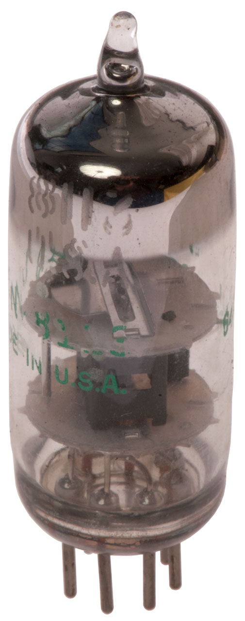
Fig 10 Tube ID
Patents
Related
References
Links
Background
This appears to be a emergency transmitter buoy.
Probably dates from the late 1950s to early 1960 because it uses tubes and Germanium Power Transistor.
Maybe a precursor to the AN/BST-1 Submarine Emergency Communications Transmitter (FAS: SECT) which started officially in 1972.
Marked:
T-347A/SRT
Buoy, Radio Transmitting
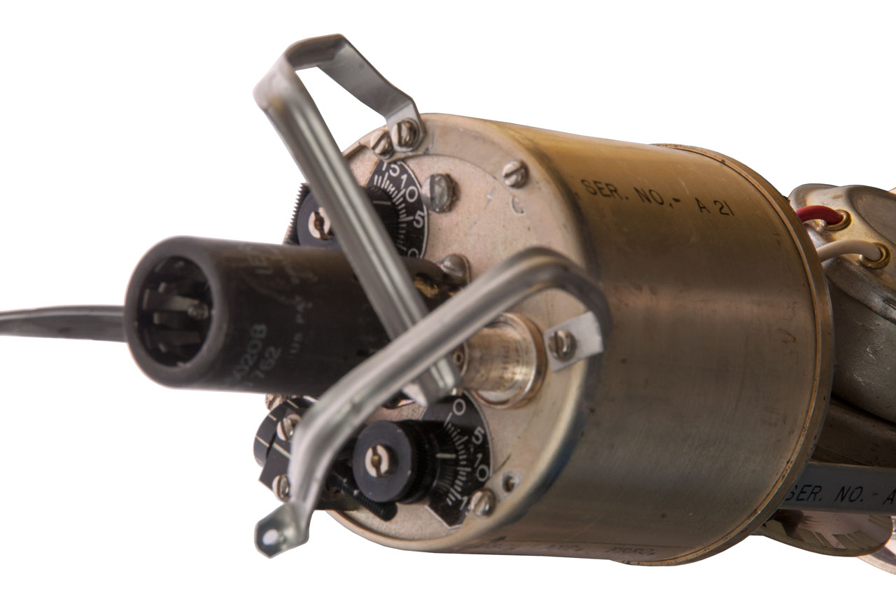
Serial A21
Navy Department
Bureau of Ships
Contractor:
Summers and Mills Inc.
Dallas, Texas
Contract NObar 875??
Description
2.985" dia x " long.
Weight:
The four main sections are:
Top - Antenna
Has BNC-f connector. BNC-m to BNC-m cable runs to transmitter output.
Not sure what metal part on outside of antenna cap (Fig 3) is.
Flotation
Radio and Code Wheel
The radio uses a 8113 tube and there are adjustments for oscillator and amplifier shown in the following table.
Osc.
Amp.
Freq.
1500
1040
111.80
1400
1023
112.38
1300
967
114.03
1200
900
115.98
1100
829
118.09
1000
763
120.30
945
742
121.58
122.13
900
693
122.62
800
630
125.04
700
560
127.61
600
498
130.35
500
431
133.23
400
366
136.40
300
300
139.64
200
239
142.78
100
181
145.28
0
152.
146.33
Note: Approach set-
ting from clockwise
direction (rotate
ccw to release
backlash.
Power Supply
Converts the battery voltage to 6.3 Volts for the tube filament and also generates the B+ (125 VDC) for the power amplifier tube plate which is probably dropped by a resistor for the screen grid.
The negative voltage (-1 VDC) for the control gird is probably generated by using a resistor between the cathode and ground.
Water Activated Battery
Photos
Fig 1 Overall View
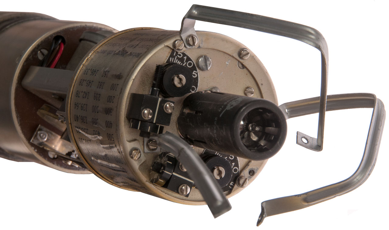
Fig 2 Opened to show code wheel and table
Pink crystals at right are battery compartment desiccant. Are they removable?
Fig 3 Antenna at top.
What is "D" shaped metal plate with one large and 2 small screws?
Ans. It connects to the BNC center terminal so is where a tape antenna used to be connected.
The metal body of the buoy is the ground for the antenna system.
Fig 4 Water Activated Battery on left, power supply and radio on right.
Arm is the vent access and probably was to be removed prior to launch.
Pin at left of battery compartment has hole for a cotter pin and maybe a "Remove Prior To Launch" flag?
The hole left after removing arm goes into battery compartment
Fig 5 the three straps came mangled, not sure how to replace them or what their function is.
Maybe to protect tube?
Note two adjustments, each with fine and coarse readouts.
Fig 6 Code wheel motor at top, code wheel below.
Fig 7 another view of adjustments.
Fig 8 Battery on left, bottom of Power Supply on right.
7uF 150 Volts 1963 date code
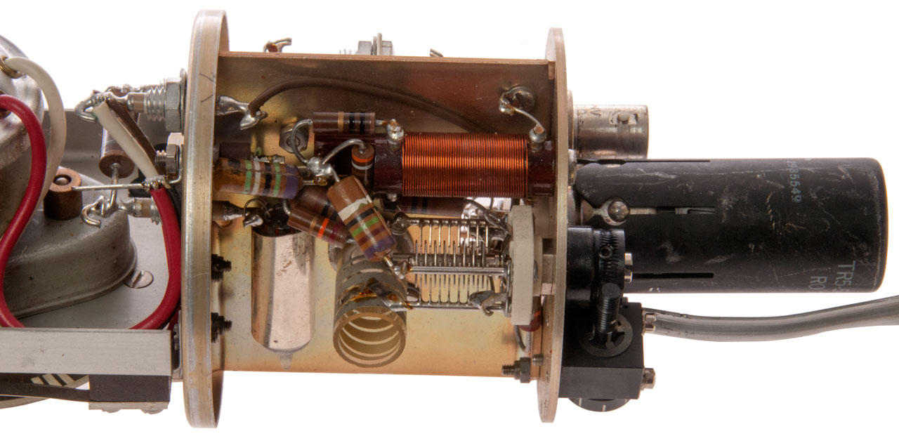
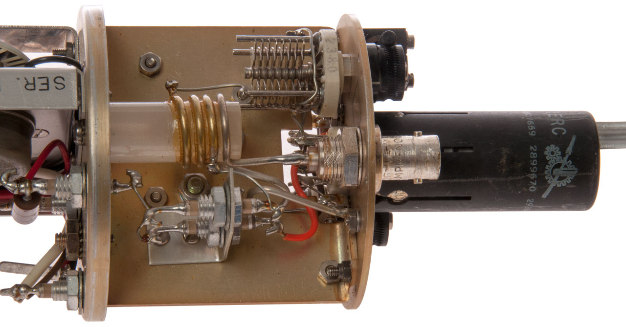
Fig 9 inside of Power Supply
I think the round 5 terminal device is a transformer used to make an oscillator using the pair of 2N1042 transistors.
The output of this transformer also drives the conventional transformer which generates the B+ for the tube.
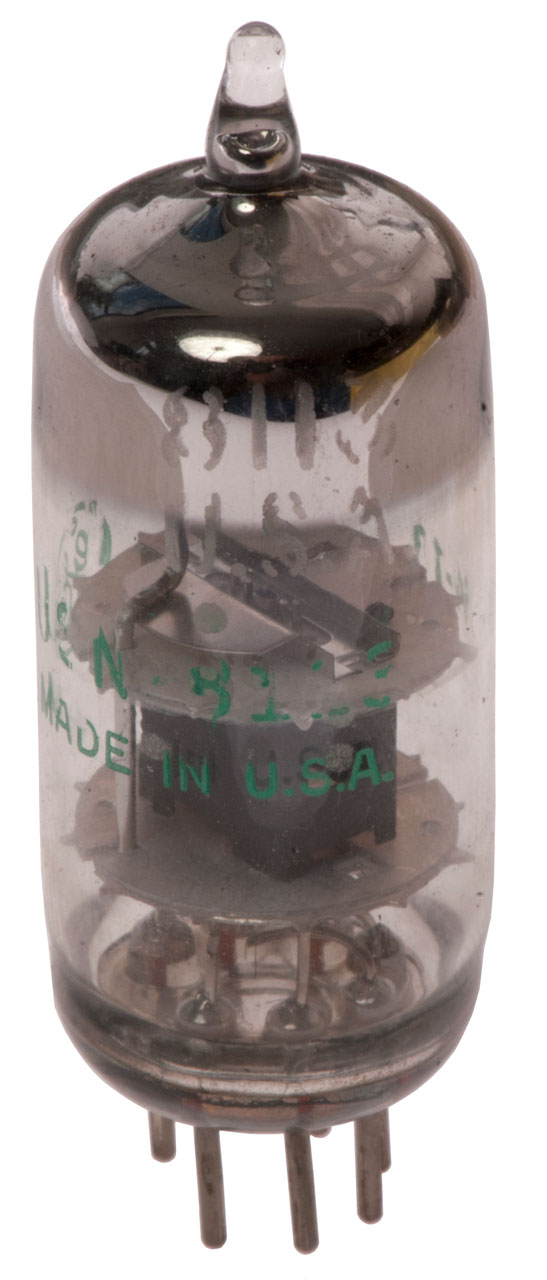
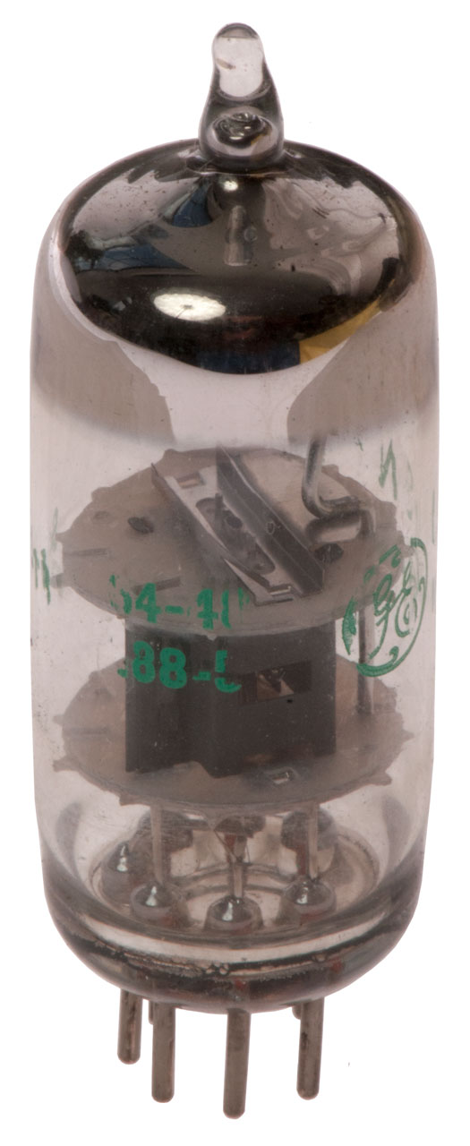
Fig 10 Tube ID: This is a VHF power amplifier operating between 111 and 147 MHz.
GE
8113 or 8116
USN-8?13
Made In U.S.A.
64-13 64-48/ 188-5 (date codes)
--------------------------------------------------------------------------
Probably equivalent to the 6CY5 (Radio Museum, Frank.pdf)
3 & 4: 6.3 V filament
2 & 7: Cathode (0 volts)
1: Grid (-1 Volt)
6 Screen Grid (80 Volts)
5 Plate (125 Volts)
Pout: 2 Watts max
Fig 11
Fig 12
Fig 13
Fig 14
Fig 15


Patents
2859695 Submarine signal bomb, Rolle Edward, 1953-02-06 - launched from sub in trouble - has dye pack to color seawater.
Tube Shield + Heat Sink
2807659 Tube clamp and shield, Woods Leroy Ralph, Internat Electric Res Corp (IERC), Sep 24, 1957 - Shield AND heat sink
2899670 Tube shield attachment, Leroy R. Woods, International Electronic Research Corporation, Aug 11, 1959 - slots that match bumps in base shield
2935549 Tube shield liner, Leroy R Woods, Int Electronic Res Corp, May 3, 1960 - mesh with many points of contact with tube for heat sink
Related
Sonobuoys
CRT-1 Sonobuoy - First one used in W.W.II
References
2N1042 PNP Germanium Transistor (Texas Instruments)
20 Watts
Vcemax: 30 Volts
Icmax: 3 Amps
Ft: 225 kHz
Package: TO-31
Links
PRC68, Alphanumeric Index of Web pages, Contact, Products for Sale
Page Created 24 November 2017