Polaroid Sonar One Step Camera
© Brooke Clarke 207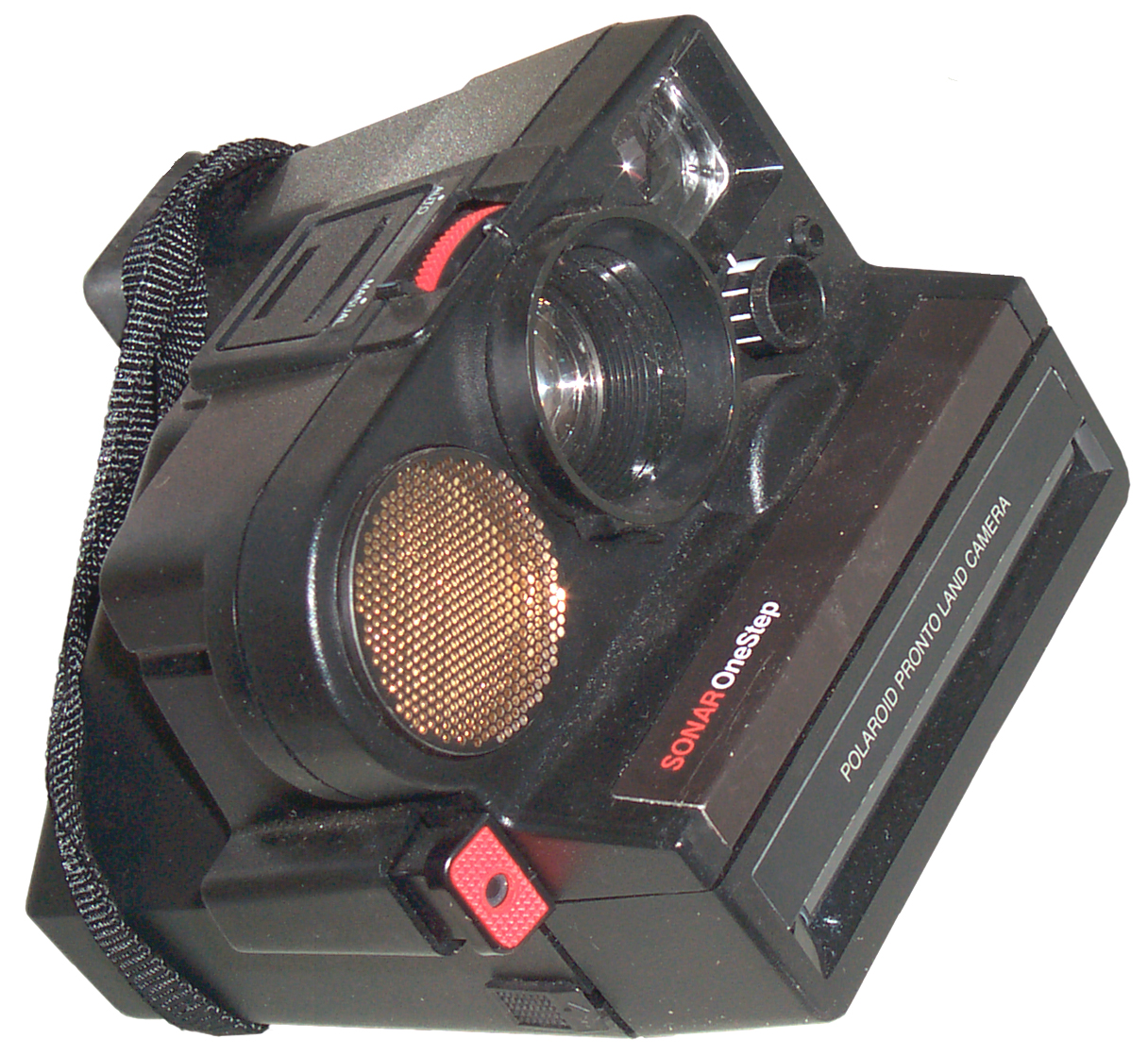
Background
The ultrasonic transducer used in
the Polaroid Sonar cameras like the One Step and SX-70 should
make an excellent wide band ultrasonic moicrophone, like you
would want to use for listening to bats.
These have a diaphragm that much
larger than the under one inch diameter electret condenser
mikes and is much more sensitive. They also were
designed for ultrasonic use with pulse signals and so
inherently have wide bandwidth.
Next is to figure out how to
take it apart and recover not only the 1.5" diameter
ultrasonic transducer but also the associated 200 VDC power
supply and amplifier if any. Got this one on eBay for
under $5. There were a number of "Sonar" type Polaroid
cameras made, the SX-70 and the "Land" series, but not all of
them have the ultrasonic transducer. But you can't miss
it if you see a photo of the camera
There's a Polaroid spin off
company that still makes these transducers but they don't seem
to serious about selling them. You can get a kit with
some transducers and circuitry for a range finder application
or a minimum order quantity of them, but no single sales and
no distributors. They do have two versions, one of which
is made from materials that can survive outdoors, so would be
a good choice for a permanent installation.
Idea
There are a couple of ways this
can be used relative to a microphone.
1) Just use the ultrasonic transducer from the camera and use all new circuitry.
2) In addition to the transducer also use the 150 VDC power supply, the pre amplifier, the final amplifier, but disable the variable Q filter and instead of the ramping gain control bring out a manual gain control.
1) Just use the ultrasonic transducer from the camera and use all new circuitry.
2) In addition to the transducer also use the 150 VDC power supply, the pre amplifier, the final amplifier, but disable the variable Q filter and instead of the ramping gain control bring out a manual gain control.
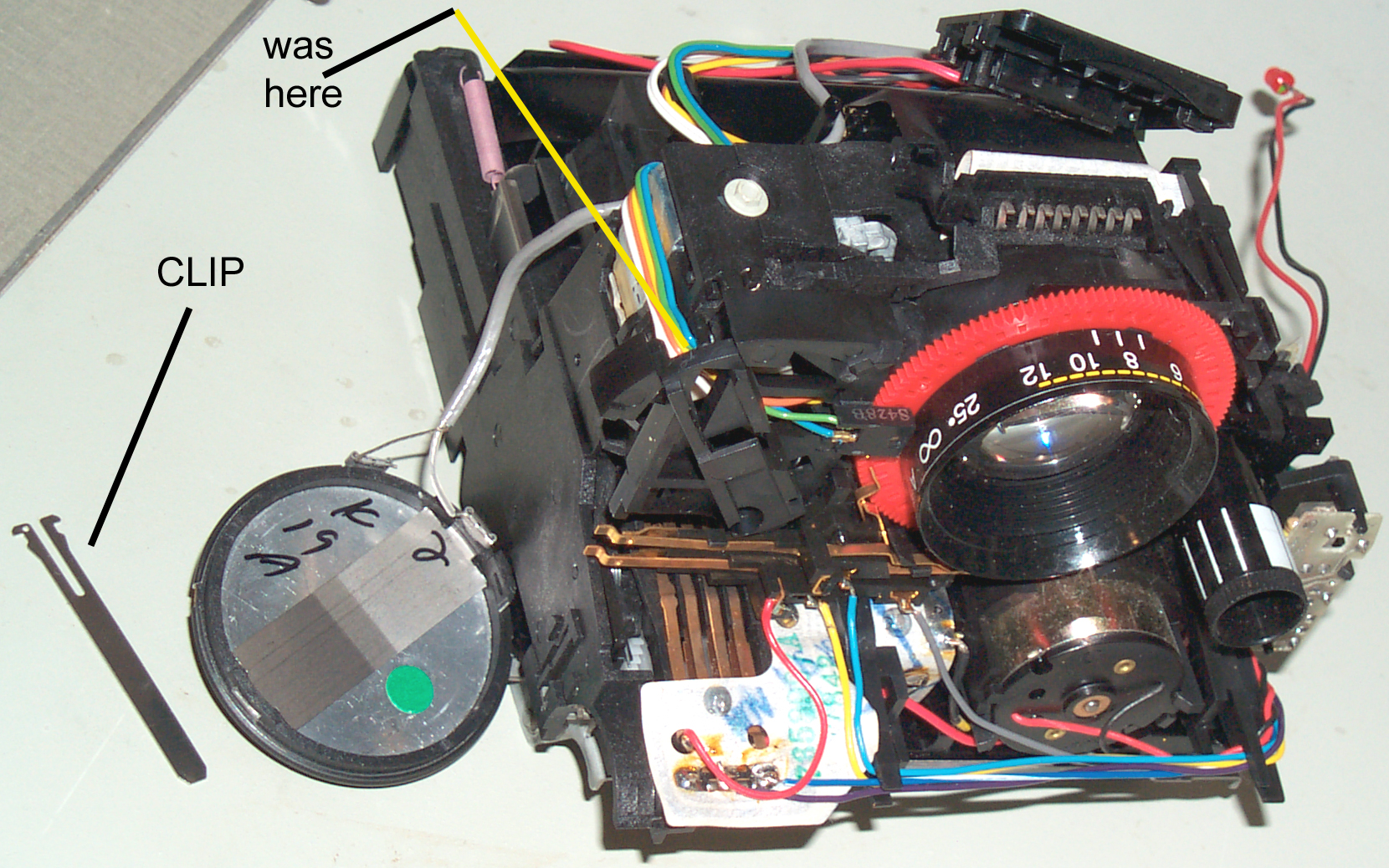
Opening
There are web sites made by
robot builders that have details on getting the ultrasonic
range finder and transducer out of the camera.
 |
 |
 |
Ultrasonic Transducer
The max dimensions are 1.7" dia x 0.38 thick. The diaphragm is about 1.5" in diameter.This is about the same as the 600 series of electrostatic transducers offered by the Polaroid spin off SensComp.
The 600 Instrument Transducer is typical and covers 20 kHz to 100 kHz with about +/- 5 dB variation. It requires 200 Volts bias and looks like about a 450 pf capacitor.
12 June 2007 - I had hoped that the Range Finder PCB contained a 200 VDC power supply for the bias voltage. But now think the bias gets generated by rectifying the transmitted pulse and charging a capacitor, which then will supply the DC bias needed to receive the echo. But I don't like the idea of sending a pulse when trying to listen to bats.
Note that the diaphragm is much larger than a wavelength at 50 kHz (about 1/4"). This implies that the off axis side lobes will be closer together and the nulls deeper than you would get using a smaller diameter microphone. For example professionals use 1/4" condenser microphones which have very well behaved frequency and spatial response at 50 kHz, but are much more expensive and less sensitive.
Range Finder PCB
The bottom of the board is marked 735710 in trace metal with solder.
Stamped in yellow ink along the wire connectors is 7840 and a symbol - maybe a week 40 of 1978 date code and QA stamp. It's double sided with vias.
At the left edge "Made In Taiwan". A (TI) logo in the lower right corner.
C6, C10, R2 are marked on the PCB but not installed. An R2 pad is being used to jump to another nearby pad.
3 each 16 pin DIP packaged ICs (5-89 transmitter, HV gen?, 0A810=TL852 receiver, 7-88=TL851 control) and an 8 pin DIP (SN28728P).
2 Inductors or Transformers both with adjustable slugs and 4 pins.
R6 is a 20 k pot.
A small blue cylindrical part that looks like a 1/8 watt resistor is connected right next to IC5-89 pins 16 and 13, is a diode
C8 has been replaced by a resistor, C7 by a SMT cap inside a glass case (looks like a diode), and C3 is now a tantalum instead of an electrolytic.
The green plastic wire guide next to the 16 pins on the PCB has the wire color for each pin.
The yellow palstic rectangle above IC1 and IC2 is a 420 kHz reasonator for the TL851 timing clock.
The shiny metal can in the upper left is T1, part of the transducer input. The round ferrite is L1 a 1 mH coil that's part of the variable Q filter.
Right next to T1 is a green cap marked .0022k630 which connects the tranducer hot lead to T1 input.
Range Finder PCB Pin Table
| Pin
# |
Wire |
Function |
| 1 |
X- |
sensor
ground |
| 2 |
X+ |
sensor
hot |
| 3 |
VIO |
Flash
& Exposure Counter |
| 4 |
B/W |
Exposure
Counter |
| 5 |
BLU |
Aux
Pluse Gen (Focus move) |
| 6 |
GRN |
Aux
Pulse Gen (Focus move) |
| 7 |
R/W |
Shutter
Flex Ckt |
| 8 |
Lite
Blu |
Shutter
Flex Ckt |
| 9 |
Yel |
Aux
Pulse Gen (focus move) |
| 10 |
Bk/W |
Ground
(batt -) |
| 11 |
Orn |
Aux
Pulse Gen (focus move) |
| 12 |
Wht |
Focus
Ratchet
Coil |
| 13 |
Wht |
Focus
Ratchet
Coil |
| 14 |
Gry |
Flash
& Shutter Sw |
| 15 |
Red |
Focus
Motor |
| 16 |
Blk |
Focus
Motor |
pin 13 part of pin 14, i.e.
permanent jumper
uxiliary Pulse Generator (focus move) = Patent 4199246 Fig 1 #26
Focus Motor = Patent 4199246 Fig 1 #24
Focus Assembly
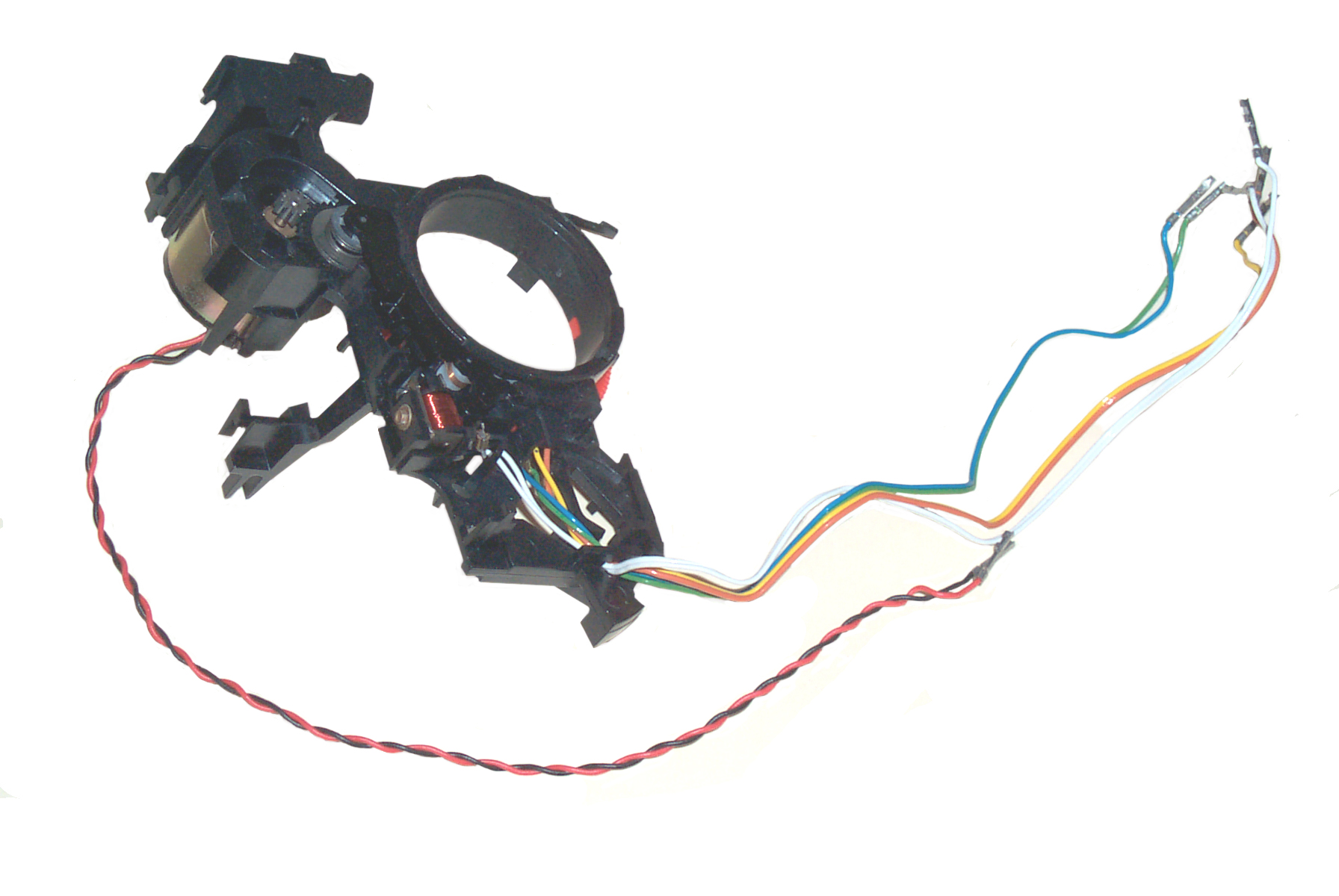
Contains the focus DC motor (twisted red/black leads) the red focus ring with 40 holes. On either side there is an LED and photo transistor (siamese blur/green and siamese yellow/orange).
There are also a siamese pair of white wires that go to a small solenoid that activates a ratchet function on the focus ring. Don't know what that's for.
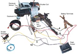
Main Assembly
Film Advance & Exposure Counter
 The
film
advance
motor is controled from the paper flex circuit although it
has a direct ground connection to the battery terminal
(black/yel bands). There are 4 leave switches that are
the digital exposure counter.
The
film
advance
motor is controled from the paper flex circuit although it
has a direct ground connection to the battery terminal
(black/yel bands). There are 4 leave switches that are
the digital exposure counter.Shutter Control
The exposure knob has a hollow shaft that allows light to fall on a photo sensor connected to the paper flex circuit. When the exposure knob is turned it rotates a filter that has different segments that are graduated in transmission thus allowing in different amounts of light. The filter is made from a single piece of light gray plastic. The hole lets the most light by, then a thin sector, a thicker sector and third thicker sector then the full thickness.There's a coil to trip the shutter.
The flex circuit has two 14 pin DIPs and one 16 pin DIP, a diode and a resistor and the exposure control 2 pin clear TO-92photo sensor. The shutter is composed of three thin metal plates that slide on plastic location pins. There's a shutter position where instead of being completly closed a small hole is left open at the center, maybe something to do with very bright light like a small f stop.
Optics PCB
Next to the expsoure knob, but on the side opposite to the lens, is what I'm calling the optics PCB.has pair of yellow wires to one pin terminal - Flash connector & shutter switch
Red & Black wires to red LED
Green/Wht wire to pin terminal - to Shutter assy
Black wire to pin terminal - battery - & BattGnd
hole cut in PCB to allow it to look forward with photo cell
Shutter Switches
This assembly has two normally closed switches that look like they are operated by the focus ring.One of these has a gray (14) wire.
The yellow wire goes to the Optics PCB and continues to the Flash Socket.
A short red wire is soldered to the Shutter Control flex circuit.
The Lite Blue (8) wire goes to the Auto Focus PCB.
Flash Socket
Four terminals:Yellow - Optics PCB - Shutter Switch assy
Violet - pin 3 of Auto Focus - Exposure Counter switch
Gray - pin 14 Auto Focus - Shutter Switch assy
Red - positive battery terminal - Exposure Counter switch
There is a longer slot in the flash socket part that sits over a row of 8 contacts that are part of the Shutter Control flex circuit.
Power Source
It's not to practical to use the
power supply since it's very mixed up with the rest of the
camera. Alternate and untested ideas are to use the
power from a single use flash
camera (typically 350 volts) or build a custom blocking oscillator.
Polaroid Patents
Patents are a very good way to
get an idea of how something works. Not as good as a
service or maintence manual, but much better than nothing.
* patents look good for this effort.
* patents look good for this effort.
152858 ? typo
3454922 - ultrasonic
pulse distance measuring device. separated fixed frequency
bursts are transmitted by a transducer, and a reflected echo
is received by the same transducer after a period of time
related to target range. When a fixed frequency
ultrasonic sound is utilized, it has been found that subjects
within the acceptance angle of the transducer, and within the
field of view of the camera, are often undetected.
3475651 Charging and Triggering
Circuits for Pulse Electrical Devices Such As Flash Lamps,
Oct. 38, 1969
3522764 Rangefinding and
Focusing System for Photographic Cameras and the like, 396/103
; 367/96; 396/105; 455/344; 455/91; D16/211- an add on dual
transducer auto focus system for the older bellows type
Polaroid camera
3563805 Thin, Flat Primary
Cells and Batteries, Feb. 16, 1971
3608454 Imbibition Interval
Timer and Annunciator 52/35 ; 52/285.3; 52/34 - i.e. wait for
film to develop timer
3617387 Battery Construction
Having Cell Components Completely Internally Bonded With
Adhesive, Nov. 2, 1971
3641889
3641889
3734780 Flat Cell Battery With
Both Terminals on One Face, May 22, 1973
3770504 High Discharge Rate
Multicell Battery, Nov. 6, 1973
3774516 Photographic
Control System and Apparatus having Self-Monitoring Features
*3791278 Photographic Apparatus
with Solenoid Powered Instrumentalities, Feb. 12, 1974
3820128 Flash Photographic
Control System, June 25, 1974
3858227 Adapter Apparatus for
Flash Firing System
3882522 Non-Cocking Springlesss Shutted Developing Two Parameter Exposure Regulation
3882522 Non-Cocking Springlesss Shutted Developing Two Parameter Exposure Regulation
3979762 Modular photographic
system, 396/541 ; 396/30 - One Step w/o Auto Focus
4005449 Flash
photographic system with camera inhibit feature
4052728 Modular photographic
system assembly, 396/33 ; 396/541 - One Step w/o Auto Focus
4064519 Regulated Strobe for
Camera with Sixth Flash Inhibit, Dec. 20, 1977
4074295 Compact Accessory
Strobe for Cameras with Battery Enclosed Film Pack, Feb. 14,
1978
*4085297 Spring force biasing
means for electroacoustical transducer components, 381/191 ;
381/173
capacitance type
electroacoustical transducers
3814864 Condensor Microphone
having a Plurality of Discrete Vibratory Surfaces, 381/174,
June 4, 1974 to Victoreen
not ultrasonic, just normal
audio
3041418 Transducers,RCA,
381/174 ; 381/163; 381/426 - improved condenser mike
4152825- battery
*4156567 Ranging and lens
focusing module for foldable cameras, May 29, 1979, 396/89 ;
396/348 - probably the foldable SX-70
*4168895 Camera having auto
focus module, Sep 25, 1979, 396/105 - probably Sonar One
Step camera (non folding)
4182561 Fast charging
electronic flash device01/08/1980 - may have schematic
4199237 Low scene brightness indicator for use in a photographic camera, Savage (Polaroid), Apr 22, 1980, 396/165 ; 396/201; 396/296
4199237 Low scene brightness indicator for use in a photographic camera, Savage (Polaroid), Apr 22, 1980, 396/165 ; 396/201; 396/296
This is very similar to the flip dot sign pixels, but is only
a single bit.
*4199246 Ultrasonic ranging
system for a camera, 396/101 ; 352/140; 367/101; 367/96;
396/105 - The preferred form of the frequency-modulated burst
is a leading half in the form of a chirp (using radar
terminology) wherein the frequency decreases with time, and a
trailing half in the form of a constant frequency equal to the
lowest frequency of the chirp.
4265530 Shutter Blade Drive System - feels like the Sonar One Step
4265530 Shutter Blade Drive System - feels like the Sonar One Step
*4331409 Photographic
apparatus with dual function sonic transducer,
396/105 ; 396/283 - block diagram outline
of ranging PCB and some curcuit details 50-65
khz is used for ranging and 3-5 khz as a speaker although at
much lower efficiency.
Links
See the problem using a Sonar camera trying to take a photo of the F-117, out of focus because the stealth applies to ultrasonic energy (See: Sonobuoy Ref 41 & 42). Hence it's possible to make a submarine that's stealthy.
SONAR
as
I Have Done it - how to open camera and remove good
stuff
SensComp - the Polaroid Electrostatic transducers & also piezo film transducers - old range finder data sheet w/schematic -
TI special ICs: TL851 & TL852
SensComp - the Polaroid Electrostatic transducers & also piezo film transducers - old range finder data sheet w/schematic -
TI special ICs: TL851 & TL852
Back to Brooke's Products for Sale, Radios, Military
Information, Sundials, Time & Frequency, Personal Home page.