TMQ-34 Meteorological Measuring Set
NSN 6660-01-170-2924
© Brooke Clarke 2005 - 2020
Description
Sensor
Display
Main Box
Display Panel
Other Items in Kit
Operation
DC Power
Battery
Charger
Manual
Related
Links
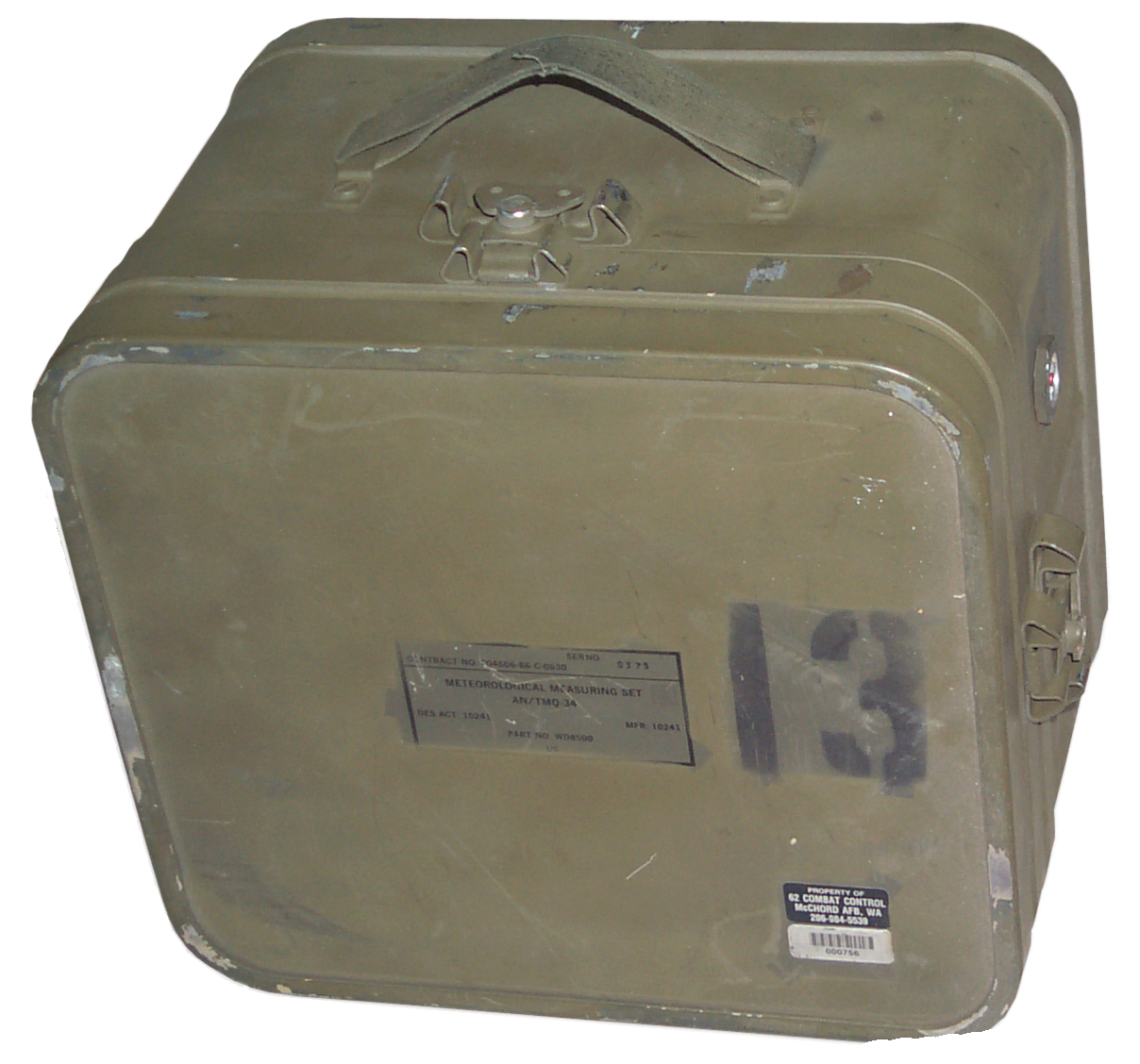
Description
The set fits into a sealed carry
case that's about 12' x 13" x 9" high.
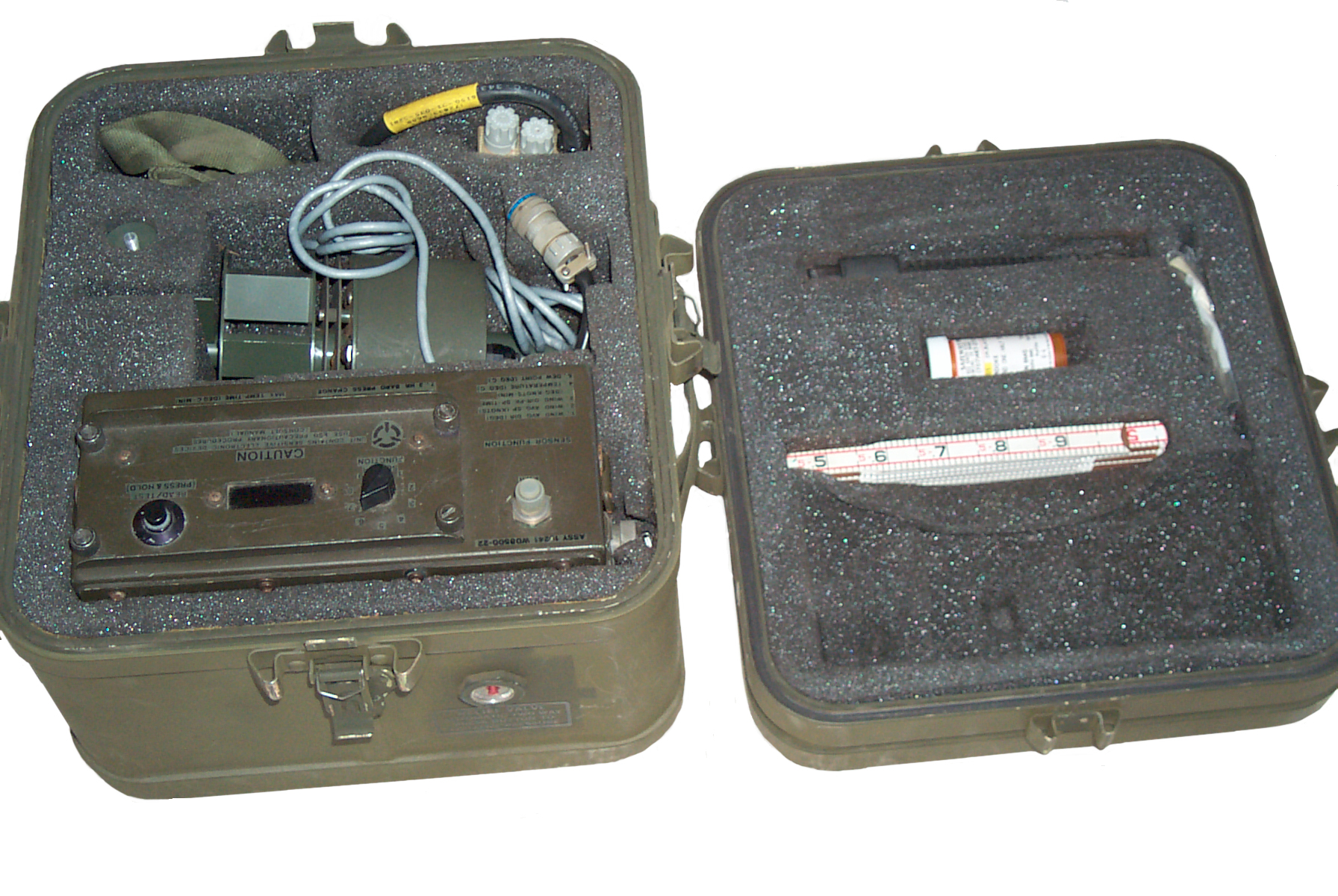
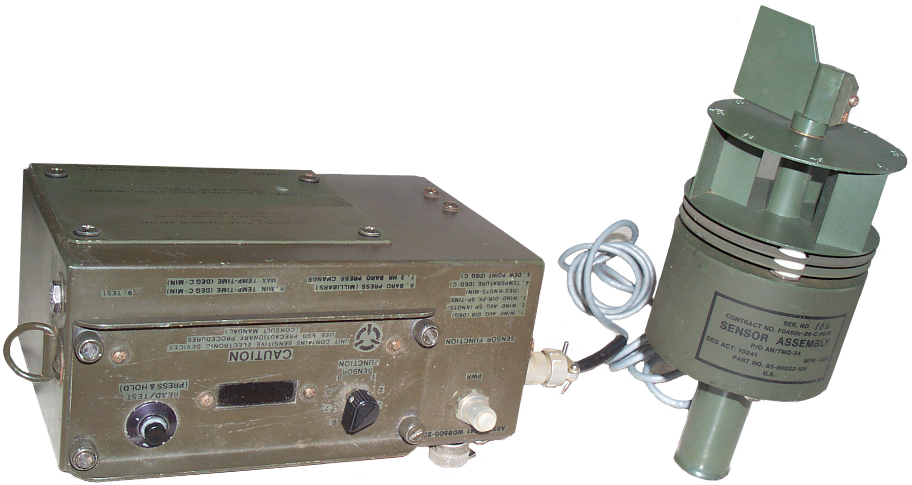
Sensor
The main component is a multi-function weather sensor that can be
either hand held or attached to a standard american camera tripod
(1/4-20 thread). It connects to the digital display unit
with a short cable (but maybe a longer cable could be used).
The sensor contains a magnetic compass so the wind direction is
reported on the Display in magnetic bearing. This way it
does not matter how the sensor is pointed, just held
still. Directly under the center of the label there's
a metal tab which when removed allows the sensor to be taken
apart. There's a wind direction scale on top of the wind
speed drum with angles marked every 45 degrees, but since the drum
turns in the wind it's not much use? If the wind speed drum
is spun manually it keeps on spinning for a long time indicting
that the bearings are very good and that the minimum wind speed
that is detectable may be low. The cable is attached to the
sensor and has a Bendix H9530-12 MS27473E10B13P connector, but
only 6 pins are installed. The sensor outputs are analog
signals in the 0.1 to 5 volt range.
The sensor connector is wired as follows:
A. Ground
B. + 10 to +15 V @ 10 ma
C. Wind Speed 0 to 100 mph (0.1 to 5 V)
D. Wind Direction 0 to 360 deg magnetic (0.1 to 5 V)
E. Temp -58 F (-50 C) to +131 F (55 C) (0.1 to 5 V)
F. Relative Humidity 0 to 100% (0.1 to 5 V)
Long Sensor Cable
When a long cable is used with JTG06RE 10-13P and JTG06RE 10-13S
connectors there will be a DC offset caused by the cable
resistance. When using an indoor voltmeter to read the
sensor to get around this an extra wire can be run from the
sensor end ground terminal (pin A) back to the indoor meter
ground terminal. This way the DC voltage drop in the
ground lead will not be part of the voltage measurement.
It's too bad that the stock TMQ-34 didn't use this method to
support extension cables. It may be possible to modify the
TMQ-34 to support this pseudo Kelvin measurement method.
Sure would be nice to have a schematic diagram for it.
Display
Marked: Computer, Assy, p/o AN/TMQ-34, Des Act: 10241, Mfr: 10241,
Part No. WD8500-22, Contract No. F04606-86-C-0630
The display unit has a selector switch to determine what the alpha
numeric LED display shows:
- Wind Avg Dir (deg)
- Wind Avg Sp (Knots)
- Wind Dir-Pk Sp-Time (Deg-Knots-Min)
- Temperature (deg C)
- Dew Point (Deg C)
- Baro Pressure (Millibars)
- 3 Hr Baro Press Change
- Min Temp-Time (deg C-min) &Max Temp-Time (deg C-min)
- Test -> all pixels on in sequence then PASS or FAIL.
On one side of the display box there's a temperature conversion
nomagram covering the range -50C/-60F to +50C/+120F, it's not
clear if a user attached a stencil or if this is a stock thing.
The display has two major parts:
Main Box
This has the battery compartment
and the barometric pressure sensor that has a tube going through
a desiccant to the outside atmosphere. The "Power" circuit
breaker and the connector for the hand held sensor.
Display Panel
This has a circuit board attached
and has all the electronics for the weather station (except for
the baro pres specific stuff). Uses a 12 to 5 Volt
DC-DC converter and a couple of crystals (1.048576 & 3.68640
MHz).
Included with the set is a
Lufkin
066D six foot folding wood ruler. Maybe this is used
to set the height of the sensor above the ground.
Another possible use would be to measure the depth of snow.
There is a "GAGE, PRECIPITION ML-614/G". (spelling should be gauge
& precipitation). Calibrated to both 2 inches and 50 mm.
The bottom end has a 0.22" diameter hole about 0.7" deep to hold
it, but what does that fit in the kit? Also there is another
part stowed inside the rain gage, but it's purpose is not clear.
Ans: I have parts of 2 different style gauges that are not
compatible.
"Kit, Sensor Test" that contains two parts:
One is a hollow plastic cone with a metal rod coming out the
pointed end. Use unknown
The other is a plastic clip that can be slipped onto the sensor
wind direction or speed rotors and when the sensor is held with
it's axis parallel to the ground the rotor should turn because of
the weight of the clip. If the rotor does not turn there's
too much friction.
The Philips screw driver is needed to open the battery
compartment.
The handle with a 1/4-20 screw on top fits the bottom of the
sensor for hand held use.
The neck strap clips onto the display so no hands are needed for
holding the display. One hand to hold the sensor and one
hand to set the display switch and press the measure button.
Operation
Instruction Sheet
Preparation:
Remove assembly and place on flat surface. Verify PWR circuit is
off (pulled out). Remove top of assembly and insert
Ni-Cad battery. Replace cover. Connect sensor assembly to
computer assembly.
Operation: Set PWR
circuit breaker to 'ON' position (pushed in). Set SENSOR
FUNCTION switch to position 9 (test). Within 10 seconds of
initial turn-on, depress and release READ/TEST button and
observe the word WAIT (2 seconds) on the panel. Wait at least 10
seconds, depress and release the Read/Test button and observe:
1) All pixels on the first and third segments illuminate and
then disappear; then the second and fourth segments
illuminate and disappear. (2) The display panel indicates PASS
three seconds after the READ/TEST is depressed. This indicates
the unit is ready for normal operation. If PASS is not
displayed, a failure code will indicate a malfunction.
Wind Direction: Set
sensor function switch to position 1. Depress and release
READ/TEST switch.
Wind Speed: Set function
switch to position 2. Depress and release READ/TEST
switch.
Temperature: Function
position 4 (READ/TEST switch).
Dew Point:
Function position 5.
Average Wind Direction:
Function position 1. Wait three minutes and depress READ/TEST
button. Average Wind Speed: Function position 2. Wait three
minutes and depress READ/TEST button.
Average Wind Speed:
Function
position 2. Wait three minutes and press READ/TEST button.
Wind Direction/Peak Speed:
Position 3.
Barometric Pressure:
Function position 5. Depress READ/TEST button.
Turn-Off: Set PWR
circuit breaker to off (pulled out). Remove battery.
Disconnect sensor assembly.
When the battery is installed the
barometric pressure sensor starts logging data so that when the 3
hour baro pressure change test is run there will be something to
compare aginst.
To get the display to turn on the Read/Test Hold button needs to
be pressed and released.
The POWER button appears to be a circuit breaker and it's normal
position is down. If it pops up there may be a
problem. You can manually lift the button to turn off the
unit.
22 April 2005 - my Loran-C receivers both lost lock and the
sferics lamp on the Loran-C filter has been flashing, so I'm
expecting a thunder storm. So started logging the baro
pressure.
PDT pm
|
Baro
Pres mb
|
3 hr
delta Baro Pres
|
Comment
|
5:07
|
997.6
|
|
installed
battery
|
6:24
|
972.5
|
|
|
6:44
|
980.2
|
|
|
6:47
|
980.2
|
|
Thunder
|
6:55
|
980.2
|
|
Rain
|
7:07
|
980.7
|
|
"
|
7:37
|
980.7
|
|
"
|
8:31
|
980.6
|
|
"
|
9:14
|
981.0
|
1.7
|
"
|
9:35 pm PDT measured inside:
- Wind Avg Dir (deg) = 226.2
- Wind Avg Sp (Knots) = 21
- Wind Dir-Pk Sp-Time (Deg-Knots-Min) = 128.1 2.2 0.
- Temperature (deg C) = 27.4 (BATT CC#2 HH#2) The strange
display caused by holding the button down.
- Dew Point (Deg C) = 18.9
- Baro Pressure (Millibars) = 981.3
- 3 Hr Baro Press Change = 1.3
- Min Temp-Time (deg C-min) & Max Temp-Time (deg C-min)=
27.4 2 28.4 2
- = FAIL if battery is low. PASS if battery is OK.
Note if the battery is changed quiclkey the 3 hour baro pressure
is not reset.
Test results depend on battery condition & how the button is
pressed, HH#3, HH#4, 502 with weak battery, and 250.4, .6, 0. with
good battery.
In the photo on the FAS web page, no longer on line, the the
sensor is mounted on a mast which seems to be supported by 3 or 4
white tape ribbons and the computer is on a stack of weather
instrument transit cases. The photo caption on the FAS web
page is:
"Airman First Class Eric Andrews takes an observation with the
TMQ-34 Tactical Meteorological Sensor."
How is the sensor attached to the mast, does it just plug in?
Barometric Sensor
The digital barometer was made by
Atmospheric Instrumentation Research (A.I.R.) which is now part of
Vaisala. Model number
on the sensor is AIR-DB-2ATS1. The code in the uP is
patented by A.I.R.
Patents held by A.I.R.:
Class 73 Measuring & Testing
335 - Hygrometer
170 - radiosonde
Class 342 Communication: Directive Radio Wave SYSTEMS &
Devices (e.g. RADAR, Radio Navigation
357.12 - GPS receiver signal processing
5345821 Relative humidity sensing apparatus Sep 13, 1994
73/335.04;
324/664; 422/98
5347285 Method and apparatus for tracking the position and
velocity of airborne instrumentation Sep 13, 1994
342/357.12;
342/352; 342/463
4907449 Meteorological data encoder for measuring
atmospheric conditions March 13, 1990
73/170.28;
73/724; 374/170
DC Power
Battery
The display box holds a BA-5557/U or BB-557/U NSN
6140-01-071-5070 battery.
The BB-557 is a Ni-Cad battery rated at 0.45 amp hours. The
battery label says to charge it at 100 ma for 6 hours.
Note the BB-557/U is a smaller version of the
BA-5590. It has the same socket as
a BB-390 or BB-590 and the socket is wired the same.
The display has the battery plug pin 1 connected to pin 2, and it
has pin 4 connected to pin 5. This puts the two "12 Volt"
batteries in parallel. So the weather station operating
voltage appears to be 10 to 15 VDC.
The design of the display battery compartment is such that a
BA-5590 will NOT fit
when the cover is removed. That's because the BB-557 is 4
3/16" long and the BA-5590 is 4 3/8" long. If they would
have made the "notch" in the display box a little longer you could
use a BA-5590 family battery when the cover was removed.
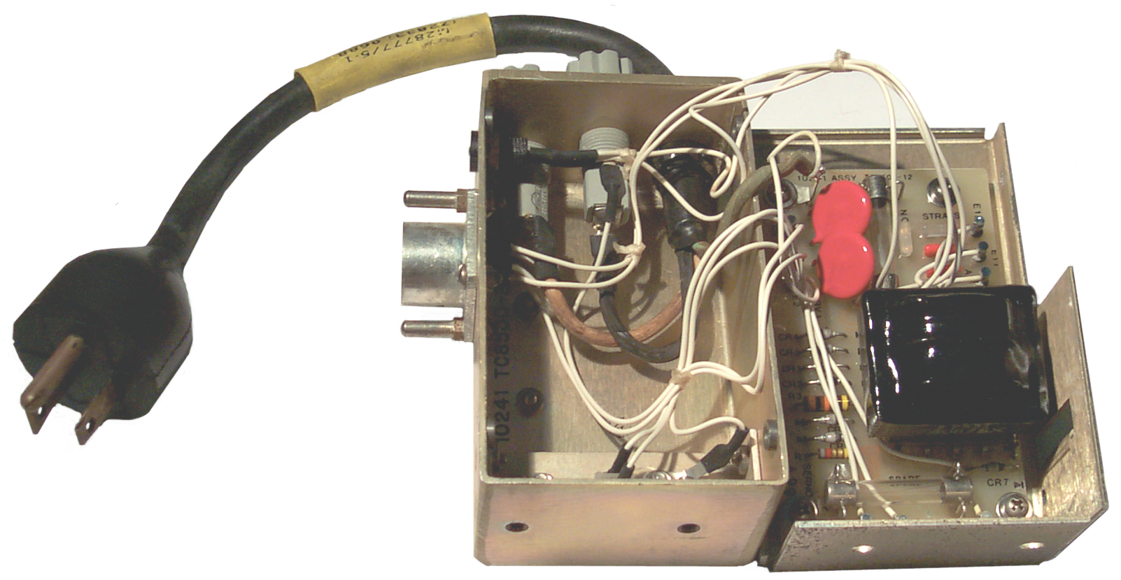
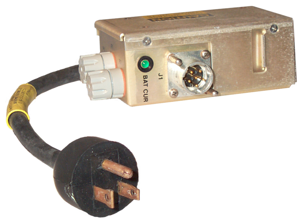
Charger

The Battery charger
plug has a jumper between pins 2 and 4 and so is charging the two
halves in series with pin 3 being the negative terminal and 5
being the positive terminal. This way you can not charge a primary
(BA-5557) battery. There are two spare 250 v, 1/4A fuses
inside the box.
The power transformer can be strapped for either 110 or 220 VAC
input. Both the input and the output are fused. There
are a couple of threaded inserts that would allow this charger to
be mounted to something, but what is not clear. Maybe the
charger is also used in other applications. The Green LED
BAT CUR indicator only comes on when current is being supplied to
the battery. So if a BA-5590 is connected there is no charge
current (no pin 3 connection in the battery) and no LED light.
The circuit appears to be a transformer fed bridge rectifier
feeding a single pass transistor. 44 is the open circuit
output voltage. If the internal resistance was 425 Ohms then
when a 27 Volt battery was connected the current would be about 40
ma. For a dead battery (20 V) the current would be about 60
ma. This may not be correct, but is close to the recomended
100 ma charge current for the BB-557/U.
The trickle charge current is about 40 ma into a string of 20
Ni-MH cells that are fully charged. This charger may be able
to charge the
5590BA Battery Adapter.
Manual
AFJQS2E1X2-206TD, AN/TMQ-34
Meteorological Measuring Set, dated 15 Apr 00. Replaces 1 Oct 99
edition
2. The following publications have been rescinded. Customers will
dispose of stock in accordance with AFI37-161.
AFJQS2E1X2-206TD, AN/TMQ-34 Meteorological Measuring Set dated
15-Apr-00 (RES)
Wanted.
Related
Weather
GMQ-33 Cloud Height Set
Cloud Sensors - based on temperature
difference looking up and down
Links
 The Battery charger
plug has a jumper between pins 2 and 4 and so is charging the two
halves in series with pin 3 being the negative terminal and 5
being the positive terminal. This way you can not charge a primary
(BA-5557) battery. There are two spare 250 v, 1/4A fuses
inside the box.
The Battery charger
plug has a jumper between pins 2 and 4 and so is charging the two
halves in series with pin 3 being the negative terminal and 5
being the positive terminal. This way you can not charge a primary
(BA-5557) battery. There are two spare 250 v, 1/4A fuses
inside the box.