TS-799/UGM-1 Teletypewriter Test Set
© Brooke Clarke 2007
|

|
Front
|
Rear when out of box
|
Background
Manuals
Front Panel
Rear Panel
Chassis
Links
Background
In order to test not only the actual
teletypewriter but also the associated modulator - demodulator (modem
aka. Data Converter) and/or the actual loop some type of data generator
is needed. This test set is an all solid state design yet only
has provision for 5 level code generation, not 5 and 8 bit. Also
provision for some rather slow baud rates. The paint scheme is light
gray. LOGSA has Technical Manuals but the -12 is not public
accessable.
My hope is to be able to use this to exercise the
Western Union 5A Stock Quotation ticker machine.
The test set chassis has covers on the top and bottom and then is
inserted into the outer box which also has 5 faces. The front
panel has a lot of filtering. Probably
TEMPEST certified.
What I call "Golden Age" construction. All discrete
components. Not even ICs., just transistors and diodes, no tubes. Note the test message:
THE QUICK BROWN FOX JUMPED OVER A LAZY DOG'S BACK
1234567890 TESTING <Ltr><Ltr><Ltr><Ltr><CR><CR><LF><Ltr>
is generated using discrete components, no ICs, no EEPROMS just resistors, capacitors, transistors and diodes!
T
|
H
|
E
|
<SP>
|
Q
|
U
|
I
|
C
|
K
|
<SP> |
B
|
R
|
O
|
W
|
N
|
<SP> |
F
|
O |
X
|
<SP> |
J
|
U
|
M
|
P
|
E
|
D
|
<SP> |
O
|
V
|
E
|
R
|
<SP> |
A
|
<SP> |
L
|
A
|
Z
|
Y
|
<SP> |
D
|
O
|
G
|
<Fig>
|
'
|
<Ltr>
|
S
|
<SP> |
B
|
A
|
C
|
K
|
<SP> |
<Fig> |
1
|
2
|
3
|
4
|
5
|
6
|
7
|
8
|
9
|
0
|
<SP> |
<Ltr> |
T
|
E
|
S
|
T
|
I
|
N
|
G
|
<Ltr> |
<Ltr> |
<Ltr> |
<Ltr> |
<CR> |
<CR> |
<LF> |
<Ltr> |
A 4 character call sign can be programmed at the end of the test
message allowing the TS-799 to be connected to a transmitter for
generating over the air Quick Brown Fox messages.
------------------------------------------ email from Rich ------------------
We used the AN/UGM-1 in our COMMEL MAINT SECTIONS to test/repair the
TT-98, TT-76, TT-4, TT-100, UGC-4, and more of the Klienschmit type of
equipment that we had............
Our COMSEC REPAIR SECTION also used them to repair/test the TTY CRYPTO
equipment.
RICH @B> }
----------------------------------------------------------------------------
The Technical Bulletin has this description:
Descriptive Data. Teletypewriter Test
Set TS-799/UGM-l is a transistorized test set, consisting of three main
functional circuits: the test message generation logic, the distortion
generation logic, and the output circuits. Additional data is listed in
a, b, and c as follows:
a. Identification.
Nomenclature . . . . . . . .Test Set, Teletypewriter TS-799/UGM-1
National stock number 6625-975-0196
Size. . . . . . . . . . . . . .8 3/32 x 17 1/8 x 8 7/16 in. (more like 10.5" x 10.5" x 21" deep
Weight . . . . . . . . . . . . . ..21 lb
References . . . . . . . . . . . .TM 11-6625-620-12 TM 11-6625-620-45-1
b. Specifications.
Output signal pattern . .. . . . . .Test message (“quick brown fox” message);
selected characters,
reversal (dot cycle)
Output signal reversal (dot cycle) speeds . . . . . . . . . . 100, 75, 37.5, 37, 23 Hz,
Test message, alternate R and Y characters selected characters. . . . . . . . . ..7 unit code at 45 or 150 baud
7.6 unit code
at 45, 50, 74 or 75 bauds
Signal distortion available. . . . . . . . . . . . ..Mark bias, space bias, space end mark end
Percent of signal distortion available.......... 0 to 50%
Accuracy of signal distortion output . . . . . . . . . . . ± 2%
Types of output current:
Neutral operation, internal supply. . . . . 20 milliamperes (mA); 60 mA
Neutral operation, external loop used . . . . 60 mA, maximum
Polar operation, external batteries required . . . . . . 30 ma
Power Requirements:
Voltage ............... 115 or 230 volts ac +/- 10%
Frequency ...........50 or 60 Hz
c. Calibration.
Time Required ................ <? nothing here>
Technique ...................... DC-low frequency
Interval .........................In accordance with TB-43-180
Manuals
TB 11-6625-620-35-1 Calibration Procedure for Teletypewriter Test Set TS-799/UGM-1
Headquarters, Depatment of the Army, Washington D.C.
13 August 1976 <including Change 1>
TB 11-6625-620-35-2 Calibration Procedure for Teletypewriter Test Set TS-800/UGM-1
Descriptive Data.
The Teletypewriter Test SetTS-80/UGM-1 (distortion analyzer) indicates
the amount of distortion present in a start-stop telegraph signal and
compares the position of the input signal transitions to an accurate
time-base signal that is generated in the time base circuits, and
indicates whether the signal transitions are occurring at the correct
time, early, or late. Additional data islisted in a, b, and c as
follows:
a. Identification.Nomenclature . . . . . . . Test Set, Teletypewriter TS-800/UGM-1
National stock number . . . . . . . . . . . . . 6625-965-0197
Size . . . . . . . . . . . . . . . . . . . . . . . . . . . .8-23/32x17-1/8x8-7/16 in.
Weight . . . . . . . . . . . . . . . . . . . . . . . . . 17-1/2 lbs
References . .. . . . . . . . . . . . . . . . . . . .TM 114625-62045-2, TM 11-6625-620-12
b. Specifications.
(1) Types of input
Neutral operation . . . . . . . . current.20 mA; 60 mA
Polar operation . . . . . . . . . . . 30 mA; polar
Input rate acceptance . . . . . 7-unit code at 45 and 150 bauds;
7.5-unit code at 45, 50, 74
and 75 bauds;
dot cycles at 23, 37, 37.5, 75,
or 100 Hz
(2) Types of distortion indicated.
Types of distortion are total peak, early peak, late peak and average for mark-to-space or space-to-mark transitions.
(3) Distortion indicators.
The percent distortion meter is a 250° front panel milliammeter
calibrated 0% to 50% (±2%) with a 1 mA sensitivity at 53
millivolts. Meter resistance is 53 ohms. There is one EARLY
indicator lamp and one LATE indicatorlamp.
(4) Power requirements.Voltage . . . . . . . . . . .115 or 230 ± 10 volts ac, single phase
Frequency . . . . . . . . . . . . . . . . 50 to 400 Hz
Power consumption . . . . . . . 16.5 watts
Refers to the TS-799 as a Pattern Generator
TM 11-6625-620-40P-1 General Support Maintenance Repair Parts and
Special Tools Liist for Test Set, Teletypewriters TS-799/UGM-1 and
TS-799A/UGM-1, TS-799/UGM-1 and TS-799A/UGM-1(NSN 6625-00-965-0196)
Headquarters, Department of the Army
28 FEBRUARY 1979
TM 11-6625-620-12, Test Set, Teletypewriter AN/UGM-l - not public
TM 11-6625-620-20P, Test Set, Teletypewriter AN/UGM-l - not public
TM11-6625-620-45-1,TestSet, Teletypewriter TS-799/UGM-l - not public
TM 11-6625-620-20P Organizational Maintenance Repair Parts and Special
Tools List for Teletypewriter Test Set AN/UGM-1(NSN 6625-00-967-0195)
Headquarters, Department of the Army
28 February 1979
Components of UGM-1
- Test Set Teletypewriter TS-800/UGM-1 or TS-800A/UGM-1
- Test Set Teletypewriter TS-799/UGM-1 or TS-799A/UGM-1
- Test Set, Relay TS-836/UGM-1
TM
11-6625-620-45-3 GS, and Depot Maintenance Manual, Test Set, Relays TS-836/UGM-1
HEADQUARTERS,DEPARTMENTOF THE ARMY
20 NOVEMBER 1967
TM 11-6625-620-40P-3 General Suppoer Maintenence Repair Parts and
Special Tools List for Test Set, Relay TS-836/UGM-1(NSN
6625-00-077-2986) (EIC: KHH)
*This manual, together with TM 11-6625-620-20P, dated 28 February 1979, superxedes TM 11-6625-620-25P-3, dated 26 August 1976.
Note the TS-836 uses +100 volt and -100 volt power supplies to drive the relays.
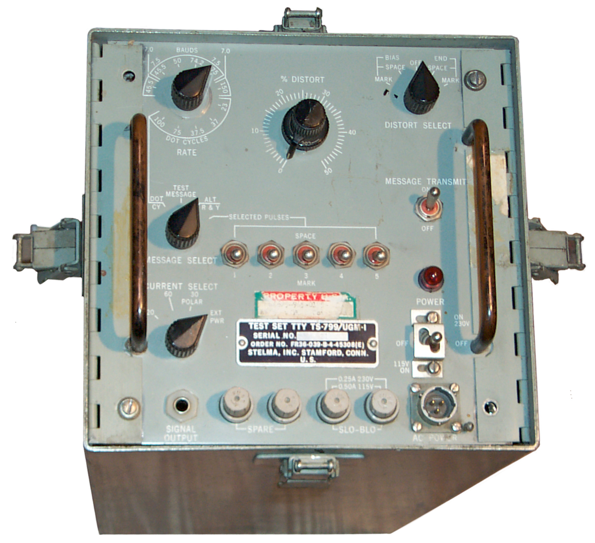
Front Panel
Label
Test Set TTY TS-799/UGM-1
Serial No. 21
Order No. FR36-039-B-4-45308(E)
Stelma, Inc. Stamford, Conn.
U.S.
RATE
There are two ranges on the switch. The top range is the baud rate slection.
45.5 baud & 7.0 units, i.e. start and 1.0 stop bits
45.5, 50, 74.2 or 75 baud & 7.5 unit code, i.e. start and 1.5 stop bits
150 baud & 7.0 units, i.e. start and 1.0 stop bits
The bottom range is the dot cycles slection.
23, 37, 37.5, 75 or 100 dot cycles
MESSAGE SELECT
- Dot Cycle based on Bauds - Rate switch
- THE QUICK BROWN FOX JUMPED OVER THE LAZY DOG'S BACK
1234567890 TESTING
- ALTernate R&Y characters.
- SELECTED PULSES - uses the 5 toggle switches to determine code
% DISTORTion
variable 0 to 50%
DISTORT SELECT
- BIAS: MARK
- BIAS: SPACE
- END: MARK
- END: SPACE
MESSAGE TRANSMIT
ON or OFF (OFF for continous Mark)
CURRENT SELECT
20, 60, 30 POLAR, EXT PWR
These are common loop currents in ma. But it's not clear how to
use the EXT PWR connection. For example what can this be used for
neutral or polar keying, what sets the loop current, what limits are on
the external power supply in terms of voltage so that the TS-799
modulator is not damaged. Works with the rear panel screw
terminals for:
- Batt, Com,+ Batt.
POWER
The front panel power switch is a
center off, up for 230 VAC on and down for 115 VAC on with a metal gate
(like a Ferrari transmission) where the gate can be positioned for
either 115 or 230 volt operation. A MO C7A neon bulb is behind
the red plastic pilot light lens. Dual fuses and spares mounted
on the front panel.
SIGNAL OUTPUT
A ¼" insulated phone jack is used for the output.
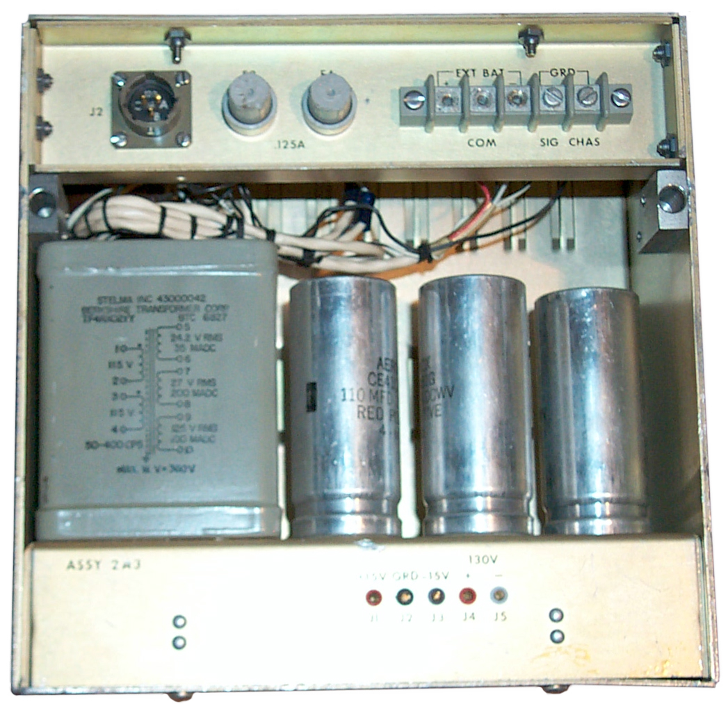
Rear Panel
In order to have Polar output two external floating power supplies need to be connected to TB1.
Positive External Battery to terminal 1.
External Battery Common to terminal 2.
Negative External Battery to terminal 3.
Terminal 4 is Signal ground.
Terminal 5 is Chassis ground.
J2 is a MS 3112E 12-3P Same connector as front panel AC so probably for AC input, but why?
Maybe the TS-799 and TS-800 can be fitted into a single outer box and the AC is daily chained?
F3 & F4 are 0.125 Amp fuses, maybe in the TTY loop.
2A1TB1 is a screw type terminal strip with 5 positions:
Ext Batt +, COM, Ext Batt -
Signal Ground
Chassis Ground
Assy 2A3 has porbe socket test points for:
J1 +15 V (+/- 0.25 volts)
J2 GRD
J3 -15 V (+/- 0.25 volts)
J4 +130 V (+/- 6.5 volts)
J5 -130 V (+/- 6.5 volts)
The power transformer has a dual 115 VAC primary and three output windings:
24.2 V @ 35 ma
27 V @ 200 ma
125 V @ 100 ma
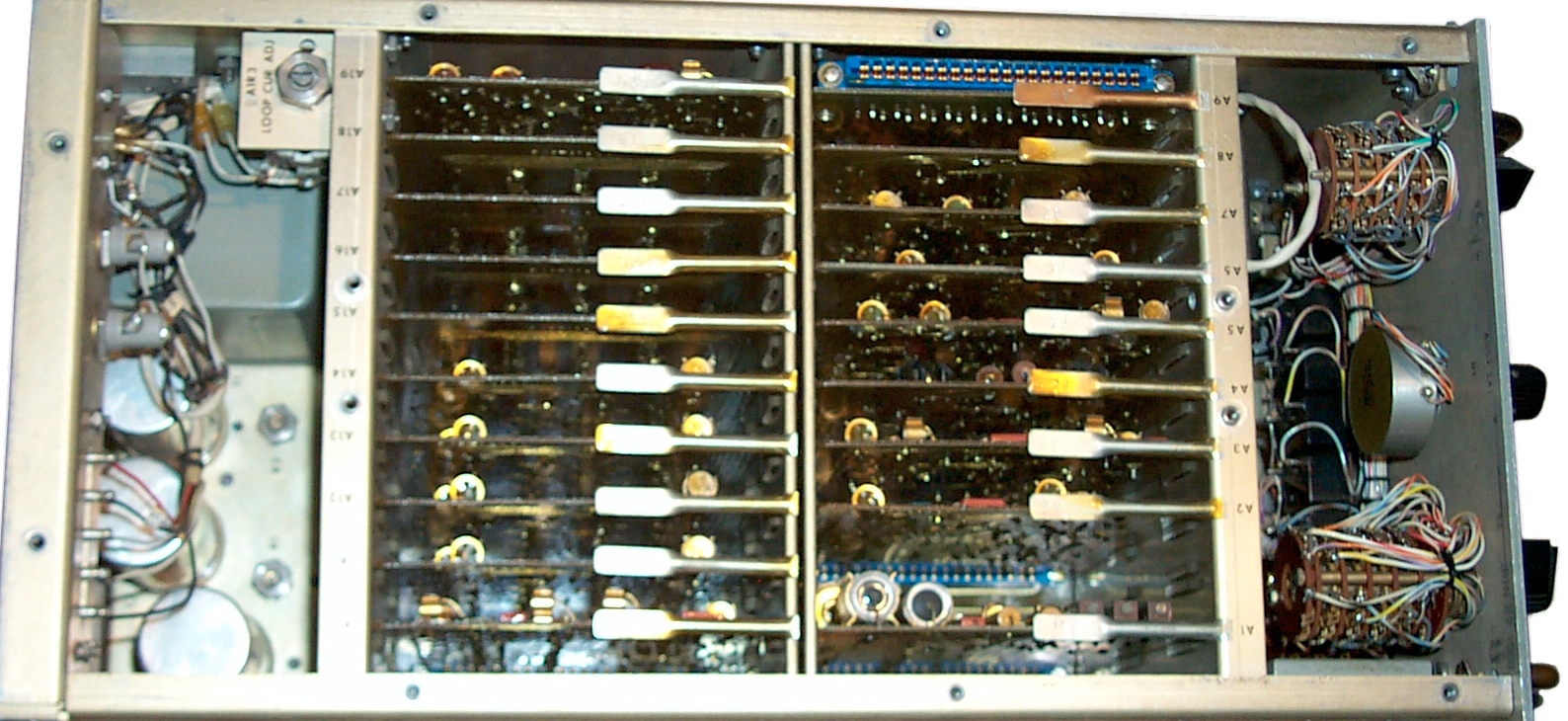
Chassis

In addition to the front panel there is
2A1A1 PCB that's related to the front panel with 3 ea 2N1305
transistors and 12 ea caps selected at test.
The power supply box has PCB 2A3A1 shown photo left, instrument rear..
There are 19 plug-in printed circuit boards.
Board
|
Function
|
Transistors
|
Diodes
|
Other
|
A1
|
Power Supply
|
|
|
|
A2
|
Distortion Ctrl
|
8 ea 2N305
|
0
|
-
|
A3
|
Distortion Gen
|
9 ea2N1305
1 ea 2N1304
|
2 ea 1N457
4 ea 1N270
|
-
|
A4
|
Output Drivers
|
2 ea 2N349
7 ea 2N1305
|
2 ea 1N270
|
Transformer 6 term
|
A5
|
Baud Counter
|
14 ea 2N1305
|
28 ea 1N270
|
-
|
A6
|
Msg combiner
|
12 ea SMB954336
|
0
|
-
|
A7
|
Msg combiner
|
11 ea SMB954336 |
2 ea 1N270
|
-
|
A8
|
Timing Gen
|
10 ea 2N1305
|
0
|
-
|
A9
|
Extender board
|
0
|
0
|
22 terminals
|
A10
|
Tens Counter
|
6 ea 2N1305
|
0
|
-
|
A11
|
Msg Xistors
|
10 ea 2N1307
|
0
|
-
|
A12
|
Msg Xistors
|
"
|
0
|
-
|
A13
|
Msg Xistors
|
"
|
0
|
-
|
A14
|
Msg Xistors
|
"
|
0
|
-
|
A15
|
Msg + 4 Call Char1 res
|
2 ea 2N1305
|
0
|
~ 200 resistors
|
A16
|
Msg res
|
"
|
0
|
-
|
A17
|
Msg res
|
"
|
0
|
-
|
A18
|
Msg res
|
"
|
0
|
-
|
A19
|
Units Counter
|
10 ea 2N1304
12 ea 2N1305
|
0
|
-
|
Note 1 - Four call characters (letters or figures) can be programmed using a soldering iron
Links
Back to Brooke's PRC68, Products for Sale, U229Pin Out for Audio Data Crypto Retransmit ,
Military Audio, Products in development, Military
Radios, Military Information,
PersonalHome
[an error occurred while processing this directive] page created 7 Sep 2007.