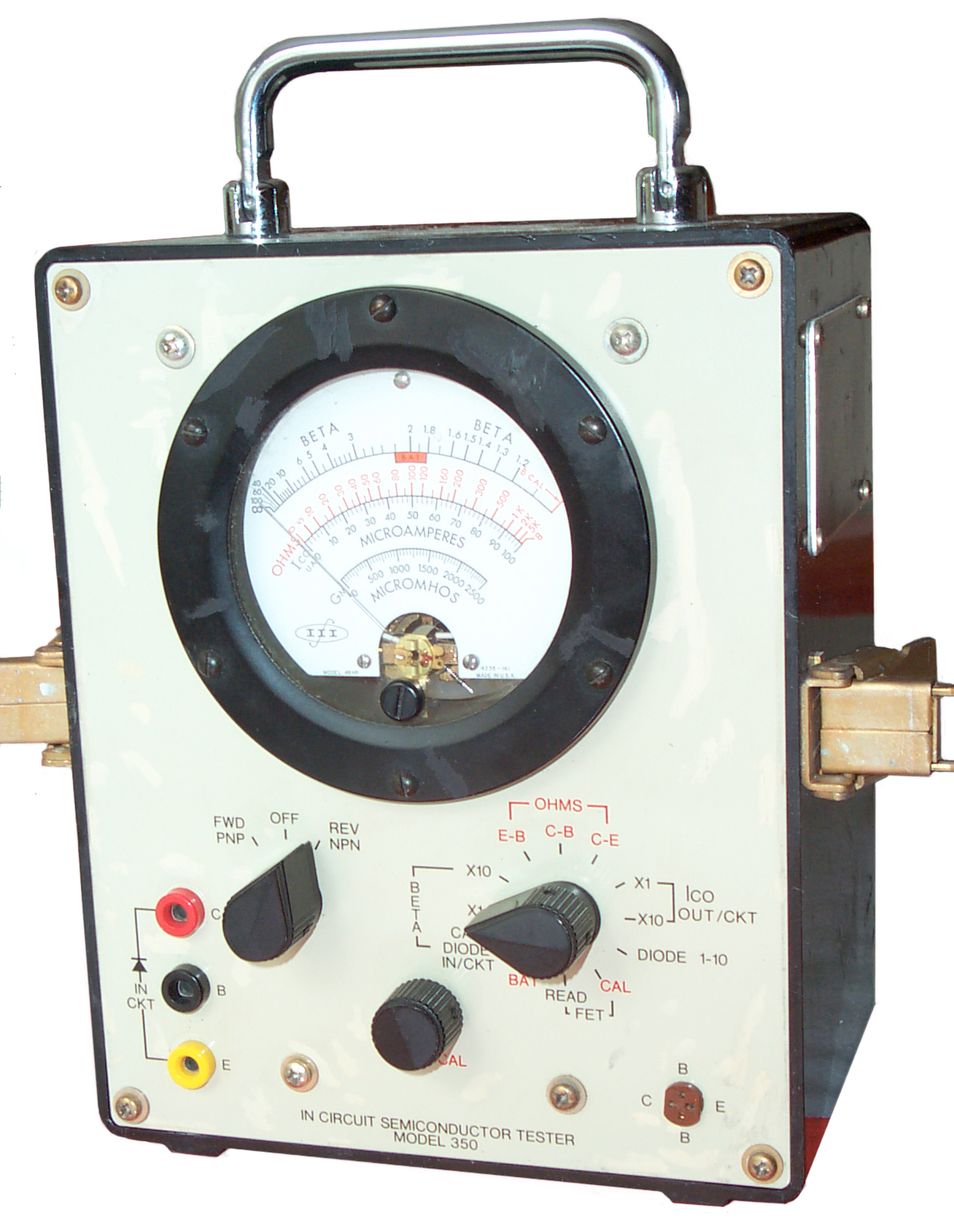
This is an in circuit transistor
(and FET and diode) tester that uses a 1 kHz AC square wave test
signal. The patented test method made this a popular
In-Circuit transistor test meter and it was made in versions A, B,
C and D.
This unit is also labeled as an III model 350 In Circuit
Transistor Tester.
Although the DC battery check worked
OK when this used instrument arrived when trying to measure the
beta of a transistor, they all test as infinite beta (equivalent
to no deflection of the meter (all the way to the left)).
The Beta Cal function works as it should and the instrument passes
the tests in the -14-3 manual. This may mean the beta is in
the hundreds but when the transistor is removed from the socket it
also reads infinite beta. I see this as a flaw in the
design. The tester may work used for In-circuit testing, but
does not work for loose transistors.
When DC stuff works and AC stuff does not then old electrolytic
capacitors are suspect. In this case there are a number of
high impedance caps that need to be replaced.
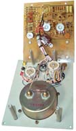
After removing the 4
cover screws and the 4 screws on the rear PCB, the rear PCB can be
hinged open allowing replacement of the caps. The photo at
the left shows the stock meter, except I've put a black dot by the
negative lead of all the electrolytic caps. It turns out
that on the trace side of the PCB there are small "+" marks for
each of the electrolytic caps. After replacing C5, C6, C7,
C10, C11, C14 and C15 (all with 22 uF 25 V) the meter is still not
working correctly. The beta zero works but not the beta test
on a loose transistor.
If you have an idea of what's going on, please
let me know.
During the troubleshooting process I made a copy of the overall
schematic and set the switches for Beta X10 and NPN then erased
all non connected paths. The resulting diagram is
considerably different from Fig 5-2 in the 14-3 TM. In
particular Fig 5-2 shows emitter DC bias being a 3k9 resistor to
+6 volts, but there is not DC connection between the transistor
the battery ground. There is a DC voltage of 2.8 Volts
between all three transistor terminals and battery ground, but not
bias. This measurement is consistent with the overall
schematic diagram.
Semiconductor Tester
2894206
Transistor beta tester, Montgomery
George Franklin, 1959-07-07, - audio frequency Joule Thief circuit
3601698
Semiconductor tester having visual display, Milton
E Thurman Jr, 1971-08-24, - This predated the M3
Semiconductor Analyzer and the current crop of Semi
testers with LCD displays.
3478264
Scr,diode and transistor analyzer, Athanase
N Tsergas, Ram
Tool, 1969-11-11, - AC line, transformer 2 voltmeters and
2 current meters + circuitry.
3778713
Transistor and diode tester, W
Jamison, 1973-12-11, - AC line, transformer single meter
switching. NPN v PNP.
3973198
In-circuit semiconductor tester, Bill
Hunt, 1976-08-03, - Huntron Tracker
3988672
Parametric tester for semiconductor devices, Brooks
E. Cowart, Fairchild,
1976-10-26, - Qualifier, Qual-Card. Maybe the Model 4000
IC Tester (CHC;
CHM: 102743172-05-01-acc.pdf)
Transistor Tester
2847645 Null
Type Transisotr Alpha Measuring Set, Thomas
(Bell
labs), 12 Aug 1958 - allows sorting into bins
2894206
Transistor Beta Tester, George Franklin Montgomery (Dept of
Commerce), Jul 7, 1959,
324/765 - blocking oscillator
2899642 Transistor
Test Set, Hussey, 11 Aug, 1959 324/768 - very simple battery
powered alpha & Ic tester, very much like the Heath IT-10.
2907954
Transistor test set,
Jr
Arthur J Radeliffe,
ITT,
1959-10-06, -
2922954
Circuit Tester, John F. Bigelow (Philco), Jan 26, 1960,
324/765
- In circuit transistor tester
2909730 Transistor
Gain-Bandwidth Test Circuit, Timm,
Bell
Labs, 20 Oct 1959 324/768 - sweep gen & Scope
3051900
In-circuit transistor tester,
Zechter
Sol,
Gruen
Harold,
Space
Systems Loral (
Philco
Ford), 1962-08-28, -
3054948 High
Frequency Mesurements, Rymaszewski,
IBM,
18 Sep, 1962 324/629; 324/158.1; 324/615; 324/639;
324/647; 324/650; 333/225 - uses 2721312
Strip/Slab line - measures cutoff frequency in the 30 to 2,400
MHz range.
3056924 Null
Type Transistor Beta Measuring Set, Thomas
(Bell
Labs), 2 Oct 1962 - direct AC Beta measurement - prior
methods used b=a/(1-a)
3076140 Transistor
Test Set, Smith,
29 Jan 1963 - Curve Tracer with stepped base currents - came
long after the Tektronix 570 (TekWiki:
1955) curve tracer (Wiki)
3201690 Wave
Transient Time Interval Measuring Circuit with Wave Comparison
Function, Embree,
Montone,
(WE),
17 Aug 1965 - sub ns
3227953
Bridge Apparatus for Determining the Input Resistance and Beta
Figure for an In-circuit Transistor, W.J. Cerveny (Hickok), Jan 4
1966,
calls:
2578455 - testing AC resistance in live circuit
2866948 Test Circuit for Interconnected Components, R.P. Witt
(Army), Dec 30 1958 -
2925554 Resistance Checker, M.H. Hayes (Link Aviation), Feb 16
1960, - for analog computer parts
2932789
3237104
Pass or fail transistor tester for indicating the combined result
of bvceo and spurious oscillation tests,
Stephen
L Merkel,
Lorain
Products Corp, 1966-02-22, - meter "Replace" or "Good"
3314008 Circuit
Employing Calibrated Variable Impedances for Measuring
Transistor Beta and Beta Cutoff Frequency, Heard,
Hughes,
11 Apr 1967 -VFO as input
3370233
Test Apparatus for Determining Beta and Leakage Current of an
In-circuit or Out-of-circuit Transistor, Oliver James Morelock
(Triplett), Feb 1968,
324/768 ; 2/160; 324/119 - includes
glove where three fingers position three probes
4801878
In-circuit transistor beta test and method, R.J. Peiffer, D.T.
Crook (HP), Jan 31, 1989,
324/765 -
4860227
Circuit for measuring characteristics of a device under test,
Toshio
Tamamura, HP,
1989-08-22, - uses mixer and frequency synthesizer
TS-1836
3287643
Method and Apparatus for
Measuring the Beta Parameter of an In-Circuit Transistor without
the Application of D.C. Biasing Thereto Nov. 22, 1966 B.
Reich (AEL)
324/768
- In-Circuit test in a way that won't damage the transistor and
that will work in spite of the surrounding circuit. The
transistor is operated as a common base amplifier with the emitter
driven by an ac coupled square wave. This causes the
collector to self bias by rectifying the emitter signal and thus
produce a DC current.
3440530
Method and Aparatus for Measuring
the Resistance of an Electrical Component which may be Shunted
by a Semiconductor Device April 22, 1969, B. Reich
324/713
- the idea is that small signals do not turn on semiconductors.
3458814
Tester for Determining the
Material Type of Transistors,
Ryan
(
AEL),
Jul 29 1969,
324/766 - Uses AC line -> step down
transformer, determines if Si or Ge
[an error occurred while processing this directive] page created 16 April
2006.
 After removing the 4
cover screws and the 4 screws on the rear PCB, the rear PCB can be
hinged open allowing replacement of the caps. The photo at
the left shows the stock meter, except I've put a black dot by the
negative lead of all the electrolytic caps. It turns out
that on the trace side of the PCB there are small "+" marks for
each of the electrolytic caps. After replacing C5, C6, C7,
C10, C11, C14 and C15 (all with 22 uF 25 V) the meter is still not
working correctly. The beta zero works but not the beta test
on a loose transistor.
After removing the 4
cover screws and the 4 screws on the rear PCB, the rear PCB can be
hinged open allowing replacement of the caps. The photo at
the left shows the stock meter, except I've put a black dot by the
negative lead of all the electrolytic caps. It turns out
that on the trace side of the PCB there are small "+" marks for
each of the electrolytic caps. After replacing C5, C6, C7,
C10, C11, C14 and C15 (all with 22 uF 25 V) the meter is still not
working correctly. The beta zero works but not the beta test
on a loose transistor.