Tektronix 1502 Metallic Time Domain Reflectometer
© Brooke Clarke, N6GCE, 2003 - 2022
Background
Models
Versions
Potential Problem
Power
Battery Packs
1502BA Battery Adapter
Operation
Velocity of Propagation
Patents
Manuals
Pliug-Ins Chart Paper
Rustrak
Related
Links
Models
Versions
Potential Problem
Power
Battery Packs
1502BA Battery Adapter
Operation
Velocity of Propagation
Patents
Manuals
Pliug-Ins Chart Paper
Rustrak
Related
Links
Background
Using a time domain reflectometer is one of the classical ways to check the condition of a transmission line. Tektronix built the 1502, and the 1503 long distance version. The word "Metallic" in the above title is there to seperate this instrument form the now common Optical TDR (OTDR) instruments used with fiber optic cables.
The 1502 has a very good reputation in terms of accuracy and reliability.
The "B" suffix units have a microcontroller that adds a lot more functionality and self tests and also use an LCD instead of a CRT. The "B" versions may not use a tunnel diode pulse generator and may be more rugged in regards the burnout problem.
I don't yet know what constitutes a "C" version of the 1502 and 1503 MTDRs.
Although designed for testing coax and twisted pair cables it has found other uses such as measuring the mositure in soil vs. depth using special probes.
The 1502 & 1503 MTDRs probably were designed for a military contract from the start. This is because they meet a long list of mil specs. I have heard that these MTDRs are common on Navy ships for finding problems with the miles of coax and twisted pair cable that needs to be maintained.
Dec 2016 - I see there are a number of "Cable Testers" on eBay that at first glance appear to be TDR instruments, but are really only capacitance meters. You can tell this because they can only find distance to an open circuit for some specified list of cables (they have a table of capacitance per foot for each type of cable). But there are a number of TDR capable hand held cable testers for low cost, but they are limited to 75 Ohm cables and only tell you distance to a short or open. Note these testers only have numeric displays, not graphical displays.
Here is a video about the hand held AEA E20/20 TDR: Coax Cable Testing with a Step TDR - these are around $2k new, but more like $400 used on eBay
The Tempo Tektronix Greenlee CableScout TV220 TDR is larger than the above unit, but that means the screen is also larger. Used these go for between $750 and $3,000.
Models
1502
The 1502 model has 8 horizontal scale factors ranging from 1 Foot/div to 200 ft/dev and either a 1X or 0.1X magnification for a range of distances of 1 foot full scale to 2,000 feet full scale.
The military designation for the 1502B is TS-4165 NSN 6625-01-255-4248
1503
The 1503 model is for longer cables, the 1503C goes to 5,000 feet per division.
Versions
A
The no suffix (or "A" version) is an analog instrument with no microcontroller and a CRT type display. I've heard that these version that use the Tunnel Diode for pulse generation have a faster pulse that's better for seeing fine detail that's missed by the "B" and "C" versions that use a different type of pulse generator.
- Optional chart recorder
- Battery Pack must be installed, even when using A.C. mains power
Potential Problem
Inside the "A" version (or no letter) units there is a Tunnel diode that's used to generate a very fast pulse (about 140 pico seconds rise time) and some sampling diodes for detecting reflected pulses. If the MTDR is connected to a line that has a DC voltage the diodes in the MTDR will be zapped. This can also happen if the line to be tested has been open for some time and has built up a static charge. This also can happen if the line is connected to an antenna that is in close proximity to other antennas where there is a nearby transmitter.
If you know of a source for the 20 ma peak current Tunnel diode please let me know. Support parts may still be available from tektronix.
June 2007 - There's a good chance that within about a year there will be a fast pulse generator circuit that be inserted to replace the tunnel diode. The idea is to be faster than the circuit used in the "B" versions so the capabilities of the "A" versions would be maintained.
I think the symptom for this problem would be that you see a trace on the CRT, but no pulse.B
Does not use a Tunnel Diode pulse generator. This is a more rugged pulser and one that has controlable pulse width, which is good for long lines where you can pump more energy into the pulse.
- Microcontroller
- Liquid Crystal Display (LCD)
- Built in diagnostic testing
- Optional RS-232 interface.
- Optional battery back
C
Does not use a Tunnel Diode pulse generator. This is a more rugged pulser and one that has controlable pulse width, which is good for long lines where you can pump more energy into the pulse.
- Microcontroller
- Liquid Crystal Display (LCD)
- Built in diagnostic testing
- Up to 128 averages
- Optional RS-232 interface
- Optional battery pack
- Optional Ethernet or Token Ring interface
- The current 1502C lists for $ 11,330 and the SP232 (RS-232) module lists for $695 (photo of 1502C with PS232)
Power
The TDR can be operated from:
- 115 VAC
- 230 VAC
- Battery Pack consisting of:
- A and B versions - 9 each Ni-Cad cells providing 10 to 13.8 VDC
- C version a Lead Acid Gel Cell
- External 12 Volt source with the positive terminal closest to the 115 socket on the 1502.
Note: Although the manual mentions using an external 12 Volt source, it's practically rather difficult to do since the connections for the battery pack are recessed in a small hole.
1502 Current consumption when using an external source:
This type of performance is typical of a switching mode power supply, although Tek calls it a DC to DC converter.
Voltage
Volts
Current
ma
Power
Watts
14
158
2.21
13
166
2.15
12
175
2.10
11
188
2.06
10
201
201
9
229
2.06
8
256
2.05
The manual says > 5 hours run time from the stock battery pack so it must supply at least (2.1 Watts * 5 hours = ) 10.5 Watt Hours. If the stock battery pack uses 9 each "C" cells then each cell needs to have about 0.97 Amp Hours ( 10.5 WH / (9 * 1.2 V). This may have been typical for a Ni-Cad "C" cell many years ago. Today you can get over 2 AH from a "AA" cell and 4.5 AH from a "C" cell. So the projected run time for a battery adapter would be:
Cell
# of
cells
Volts
A.H/cell
Watt
Hours
Run
Time
hrs
1/2 Run*
Time
hrs
AA
8
9.6
2.1
20.16
9.6
4.8
AA
9
10.8
2.1
22.68
10.8
5.4
AA
10
12.0
2.1
25.2
12
6.0
C
9
10.8
4.5
413.1
197
98
*After finding out that the stock battery pack is rated at 1.8AH @ 150 ma and most AH specs are at C/20 you need to derate the AH rating by about 1/2 for use with the 1502.
A "C" cell adapter would provide a huge improvement in run time, but is very difficult (expensive) to make and the internal charger is putting out only 150 ma and so the time to charge would be considerably longer than normal.
The "AA" cell battery adapter should offer performance similar to a stock battery pack and be much easier to make..
Note
When I received my 1502 the CRT would not light up, although the battery voltage meter would jump to full scale. This is a symptom of a missing battery pack.
The designers of the 1502 assumed that it would always be used in the field from the plug-in rechargeable battery pack. In order to maintain the battery pack there are monitoring circuits whose job it is to shut down the battery charging (and power supply) if the voltage on the battery pack is too high or too low. This means that if you try to use the 1502 with an A.C. supply and without the battery pack installed, IT WILL NOT WORK.
This is spelled out on page 3-10 of the Army manual TM 9-4935-601-14-3&P.
The "B" and "C" versions may work without a battery from the A.C. line. The "B"and "C" versions also have a LTC-7B 3.5V 750 mAH Lithium primary memory keep alive battery and/or a 3.0 V Silver Oxide battery p/n 146-00079-00 located on the main board.
There are a number of ways around this problem.
- Install a Tek battery - no longer available
for s/n through B109999 the battery is p/n 016-0595-00
for s/n B110000 and higher the p/n is 016-0595-01
146-0066-00 fits what?The old replacement battery 016-0595-00 was a NICAD : BATTERY,STORAGE; 10.8V,1.8AH @ 150MA,(9)C CELLS,NICAD
The new 146-0066-00 BATTERY; 12V LEAD ACID,3.4MAH,5.28 X 2.36 X 2.6 RECTANGLE. and has different volts and connections.- Install a 1502BA Battery Adapter
- Instead of a battery pack some type of circuit could be installed to fool the battery monitor and allow the A.C. line to power the 1502. This might be a resistor of 12V / (150 ma charging current) = 80 Ohms rated for 12V * .15A = 2 Watts.
- Modify the 1502 battery monitoring circuit to defeat the over voltage battery protection. - Not a good thing of you want to use rechargeable batteries but may be desirable to use Alkaline batteries in an adapter.
Power Supply Modification.pdf - remove Q6549 from the power supply pdf by W NielsenNote
After doing a couple of "Run the Battery Flat" tests I tried powering the 1502 from just the A.C. line without a battery and it now works OK. Even though the manual says it should not and it did not when I received it. I think I have done something to the 1502, but not sure just what.
Commercial Battery Pack
30 April 2007 - I've heard that
Avex offers a
replacement battery pack.
Battery Packs
The Battery Packs shown in Red all are of the 9 "C" cell type. Do they all have the same mechanical outline?
Model
Batt pack
Tek p/n
Description
1502 s/n B010100 - B109999
016-0595-00 9 "C" cell Ni-Cad 1502 s/n >= B110000
016-0595-01 9 "C" cell Ni-Cad 1502 s/n >=R118365
146-0065-00 9 "C" cell Ni-Cad
10.8 V
2.0AH @ 200 ma
1503
016-0595-00
016-0595-01
9 "C" cell Ni-Cad 1503 s/n >=R097969
146-0065-00 9 "C" cell Ni-Cad 1502B s/n< R010100 016-0813-01 9 "C" cell Ni-Cad
10.8 V
2 AH @ 0.2C(200ma)
5.188x3.031x2.219"
1502B s/n>= R010100
146-0065-00 9 "C" cell Ni-Cad
10.8 V
2.0AH @ 200 ma1503B s/n< R010100 016-0813-01 9 "C" cell Ni-Cad
10.8 V
2 AH @ 0.2C(200ma)
5.188x3.031x2.219"1503B s/n>= R010100
146-0065-00 9 "C" cell Ni-Cad
10.8 V
2.0AH @ 200 ma1502C
146-0066-00
12V Lead Calcium
5.28x2.36x2.6"
3.4 AH @ C/20
1503C
146-0066-00 12V Lead Calcium
5.28x2.36x2.6"
3.4 AH @ C/20
Note although "C" is used in the Tek literature the actual size of the cells may be what's called "CS" which is 43mm long x 23 mm dia whereas the standard tabbed "C" is 50 mm long x 26 mm dia.
1500BA Battery Adapter
I need information from pwople who have different versions of the 1502 or 1503 about the physical size of their battery packs. Let me know about your battery pack, 150x Model & Serial number and battery pack Model number & physical size.
Something I'm working on. This is in the paper design stages as of 15 Jan 2004. Currently looking at using 9 "AA" cell batteries. Doing experiments powering my 1502 from 9 "AA" Ni-MH cells and measuring the run time and checking the charging functionality.
1502 Battery Run Down Tests
(#1) 9 each MaHa 1.8 Amp Hour "AA" cells used for the battery pack and charged in the MaHa C777+ charger.
Run time over 6 hours.
(#2) Allowed the 1502 to charge the batteries from test #1 overnite.
Batteries did not get hot, like they do on the C777+ charger.
Run time very close to 8 hours.
To see other Battery Adapters I make, go to PRC68.com
Operation
I've just started to use my 1502 with a prototype home made battery pack.
OE-254 Antenna
This antenna has a BALUN and so tests as a DC short. When I connected it to the 1502 the trace showed a small (1/2 div * 20 Ft/dev) length of higher impedance then a flat 50 Ohm section of line. I tried pressing the three Cable Dielectric buttons and the center one (Solid PTFE) caused the length to display as 80 feet for the 50 Ohm section which might actually be a nominal 75 foot cable. I have a 10 foot section of 75 Ohm cable on the end of the larger coax and that's what caused the bump. At the far end the display decays down to zero, consistent with a DC short BALUN.
Note that TDR works with open or shorted cables.
Velocity of Propagation
The 1502 has pushbutton switches for a couple of solid dielectrics and a third to select a variable input. The 1502B just uses a couple of rotary switches allowing more accurate setting of the Vp.
Dielectric
Probable Vp
Jelly Filled
0.64
Polyethylene (PIC, PE or SPE)
0.66
PTFE (Teflon ®) or TFE
0.70
Pulp Insulation
0.72
Foam or Cellular PE (FPE)
0.78
Semi-solid PE (SSPE)
0.84
Air (helical spacers)
0.98
Vacuum
1.0
Some of the above Dielectric materials are clearly those used with twisted pairs indicating that TDR methods are intended for use on both coaxial and twisted pairs.
Patents
These may or may not apply to
the 1500.
2649570 Test equipment and method for measuring reflection coefficient, Frederick E Radcliffe, Bell Labs, 1953-08-18, -
2651752 Electrical fault finder, Andre J Devot, Tobe Deutschmann, 1953-09-08, - Tubes & CRT pulse TDR
3170124 Tunnel diode pulse generator having independently controllable pulse width and repetition rate, Emmanuel E Candilis, HP, 1965-02-16, -
3434049 Time Domain Reflectometry System Having a Current Source for Locating Discontinuities in a Transmission Line, George J. Frye, Tektronix, Mar 18 1969, 324/533 ; 331/107R - 1502 Uses a Tunnel Diode (32) for fast pulse generation.
3621325 Time delay reflectometer, Lee R Moffitt, HP, 1971-11-16, -
3771056 Display Baseline Stabilization Circuit, H.A. Zimmerman (Tek), Nov 6 1973, 324/642 ; 324/130
2649570 Test equipment and method for measuring reflection coefficient, Frederick E Radcliffe, Bell Labs, 1953-08-18, -
2651752 Electrical fault finder, Andre J Devot, Tobe Deutschmann, 1953-09-08, - Tubes & CRT pulse TDR
3170124 Tunnel diode pulse generator having independently controllable pulse width and repetition rate, Emmanuel E Candilis, HP, 1965-02-16, -
3434049 Time Domain Reflectometry System Having a Current Source for Locating Discontinuities in a Transmission Line, George J. Frye, Tektronix, Mar 18 1969, 324/533 ; 331/107R - 1502 Uses a Tunnel Diode (32) for fast pulse generation.
Calls:
2651752 Electrical Fault Finder, A. J. Devot (Tobe Deutschmann), Jan 1948, 324/533 ; 33/501.03; 368/116 - Tube type TDR
3170124 Tunnel Diode Pulse Generator having Independently Controllable Pulse Width and Repetition Rate, E.E. Candlis (HP), Feb 16 1965, 331/111 ; 327/172; 327/195; 331/107T
3191065 Sampling Circuit, G. Vargiu (HP), Jun 22 1965, 327/93 ; 327/172; 327/343; 329/312; 332/184
3211997 Fault Locating Means for Electric Power Transmission Lines, having means for Recording, Reproducing and Displaying Transmitted and Reflected Signals, M. Hara (Nippon), Oct 12 1965, 324/533
3234340 Telephone Line Trouble Locator, K.E. Youdan, Feb 8 1966, 324/534 ; 324/644; 379/22.03 - tube type TDR
3264494 Pulse Generator Providing Fast Rise and Fall Time Pulses having an Adjustable Repetition Rate over a Broad Frequency Range, E.E. Candilis (HP), Aug 2 1966, 327/114 ; 327/170; 327/195; 331/107T
3286104 Variable-width Transistor Pulse Generator employing Variable Capacitive Phase-shift Circuit for Consecutive Switching of two Tunnel Diodes, J-J Laupretre (Compagnie des Machines Bull), Nov 15 1966, 327/184 ; 327/172; 327/195
3617880
Time domain reflectometer, George D Cormack, Ronald P Manning,
Northern Electric, 2651752 Electrical Fault Finder, A. J. Devot (Tobe Deutschmann), Jan 1948, 324/533 ; 33/501.03; 368/116 - Tube type TDR
3170124 Tunnel Diode Pulse Generator having Independently Controllable Pulse Width and Repetition Rate, E.E. Candlis (HP), Feb 16 1965, 331/111 ; 327/172; 327/195; 331/107T
3191065 Sampling Circuit, G. Vargiu (HP), Jun 22 1965, 327/93 ; 327/172; 327/343; 329/312; 332/184
3211997 Fault Locating Means for Electric Power Transmission Lines, having means for Recording, Reproducing and Displaying Transmitted and Reflected Signals, M. Hara (Nippon), Oct 12 1965, 324/533
3234340 Telephone Line Trouble Locator, K.E. Youdan, Feb 8 1966, 324/534 ; 324/644; 379/22.03 - tube type TDR
3264494 Pulse Generator Providing Fast Rise and Fall Time Pulses having an Adjustable Repetition Rate over a Broad Frequency Range, E.E. Candilis (HP), Aug 2 1966, 327/114 ; 327/170; 327/195; 331/107T
3286104 Variable-width Transistor Pulse Generator employing Variable Capacitive Phase-shift Circuit for Consecutive Switching of two Tunnel Diodes, J-J Laupretre (Compagnie des Machines Bull), Nov 15 1966, 327/184 ; 327/172; 327/195
3621325 Time delay reflectometer, Lee R Moffitt, HP, 1971-11-16, -
3771056 Display Baseline Stabilization Circuit, H.A. Zimmerman (Tek), Nov 6 1973, 324/642 ; 324/130
Calls:
3248655 Ratchet Memory circuit and Sampling System employing such Circuit, J.R. Kobbe (Tek), Apr 26 1966, 327/94 ; 327/118; 327/126 - sampling scope
3529249 Sample and Store apparatus including means to Compensate for Base Line Drift, L.L. Jasper (TI), Sep 15 1970, 327/92 ; 324/102; 324/130; 327/302; 327/423; 327/494
2994825 Voltage to Time-interval Converter, T.C. Anderson (HP), Aug 1 1961, 327/261 ; 324/111; 324/120; 324/99R; 327/100; 330/51; 330/69; 330/9; 330/97; 340/870.19; 341/118; 341/169; 368/121
3532980 Peak Voltage Reader, H.C. Tucker (Monsanto), Oct 6 1970, 324/103P ; 324/111; 324/130; 327/551
4069447
Stabilized high-efficiency sampling system, G.J. Frye (Tek),
Jan 17 1978, 327/91 ; 365/149
3248655 Ratchet Memory circuit and Sampling System employing such Circuit, J.R. Kobbe (Tek), Apr 26 1966, 327/94 ; 327/118; 327/126 - sampling scope
3529249 Sample and Store apparatus including means to Compensate for Base Line Drift, L.L. Jasper (TI), Sep 15 1970, 327/92 ; 324/102; 324/130; 327/302; 327/423; 327/494
2994825 Voltage to Time-interval Converter, T.C. Anderson (HP), Aug 1 1961, 327/261 ; 324/111; 324/120; 324/99R; 327/100; 330/51; 330/69; 330/9; 330/97; 340/870.19; 341/118; 341/169; 368/121
3532980 Peak Voltage Reader, H.C. Tucker (Monsanto), Oct 6 1970, 324/103P ; 324/111; 324/130; 327/551
Calls:
3059228 Multiplexing Sample and Hold Circuit, R.M. Beck (HP), Oct 16 1962, 340/870.06 ; 340/870.11; 340/870.18; 340/870.21; 340/870.24; 341/122; 370/537
3157859 Electronic Analog Storage Device, L.C. Moore (Navy), Nov 17 1964, 365/45 ; 341/122; 365/149; 365/204
3380035 Multiple Element Analog Storage system, K.J. Hecker (Navy), Apr 23 1968, 365/45 ; 365/149; 365/210.1; 365/233.1
3474259 Sample and Hold Circuit, R.P. Rodgers (Singer General Precision), Oct 21 1969, 327/95 ; 327/432; 327/96; 330/253; 330/3; 330/51; 330/69; 365/149; 365/45
3701909 Peak and Hold System, W.V. Holmes, Oct 31 1972, 327/95 ; 327/58
3753132 Sample and Hold Circuit, E.R. Hill (Navy), Aug 14 1973, 327/95 ; 327/379
4438404
Signal sampling system, H. Philipp (Tek), Mar 20 1984, 327/263
; 327/100
3059228 Multiplexing Sample and Hold Circuit, R.M. Beck (HP), Oct 16 1962, 340/870.06 ; 340/870.11; 340/870.18; 340/870.21; 340/870.24; 341/122; 370/537
3157859 Electronic Analog Storage Device, L.C. Moore (Navy), Nov 17 1964, 365/45 ; 341/122; 365/149; 365/204
3380035 Multiple Element Analog Storage system, K.J. Hecker (Navy), Apr 23 1968, 365/45 ; 365/149; 365/210.1; 365/233.1
3474259 Sample and Hold Circuit, R.P. Rodgers (Singer General Precision), Oct 21 1969, 327/95 ; 327/432; 327/96; 330/253; 330/3; 330/51; 330/69; 365/149; 365/45
3701909 Peak and Hold System, W.V. Holmes, Oct 31 1972, 327/95 ; 327/58
3753132 Sample and Hold Circuit, E.R. Hill (Navy), Aug 14 1973, 327/95 ; 327/379
Calls:
4121164 Automatic trigger circuit Oct 17, 1978
4204173 Tuning circuit with provisions for reducing pulse width jitter May 20, 1980
4223267 Circuit arrangement for measuring pulse widths Sep 16, 1980
4442442
Data synchronization system for graphic recording apparatus,
G.B. O'Dell (Tek), Apr 10, 1984, 346/136
4121164 Automatic trigger circuit Oct 17, 1978
4204173 Tuning circuit with provisions for reducing pulse width jitter May 20, 1980
4223267 Circuit arrangement for measuring pulse widths Sep 16, 1980
Calls:
3275208 Incremental Tape Drive System, E. Poumakis (Potter Inst), Sep 1966
3605111 Trace-interrupting Multichannel Recorder, R.H. Schmoll (Clevite), Sep 14 1971
4038664 Recording chart lock Jul 26, 1977
4172259 Graphic recording apparatus compensated for record medium velocity changes Oct 23, 1979
4245228 Laser plotter Jan 13, 1981
4497575
Optical fiber test instrument calibrator, H. Philipp (Tek),
Feb 5 1985, 356/73.1 ; 356/243.1; 385/123275208 Incremental Tape Drive System, E. Poumakis (Potter Inst), Sep 1966
3605111 Trace-interrupting Multichannel Recorder, R.H. Schmoll (Clevite), Sep 14 1971
4038664 Recording chart lock Jul 26, 1977
4172259 Graphic recording apparatus compensated for record medium velocity changes Oct 23, 1979
4245228 Laser plotter Jan 13, 1981
Calls:
4136929 Apparatus for generating light pulse train Jan 30, 1979
4167328 Passive optical range simulator device Sep 11, 1979
4549783
Connector for optically connecting an electrically-energizable
light, R. Schmachtenberg, III (Tek), Oct 29 1985, 385/88
; 385/924136929 Apparatus for generating light pulse train Jan 30, 1979
4167328 Passive optical range simulator device Sep 11, 1979
Calls:
3942859 Electrical conductor with light indicating means Mar 9, 1976
4081208 Optical and electrical conduit termination means for circuit board Mar 28, 1978
4152043 Electrostatic optical switch with electrical connection to coated optical fiber May 1, 1979
4294512 Optoelectronic interface apparatus Oct 13, 1981
4303301 Cable coupling for electrical current lines and light conductors Dec 1, 1981
4312563 Connectors for sealed containers Jan 26, 1982
4465333 Electro-optical plug-in interconnection Aug 14, 1984
Manuals
1502
- TM 9-4935-601-14-3&P is a 137 page Army manual dated Aug. 1986. This is a combined operation and service manual complete with schematics, parts list and calibration info.
- TM 9-6625-2801-14&P is a 76 page manual dated Aug. 1981 and is closer to the commercial manual.
- 1500-Series Chart Recorder is a 50 page manual including schematics and mechanical parts. Covers part numbers 016-0506-03 and 016-0506-04 and up. This is only for the Chart Recorders with the DB-15(m) connector used on the 1502 and 1503, not the later recorders used with the "B" and "C" version Cable Testers.
Note: the multi-page schematics have been stitched back into a single page. This makes viewing much easier on the computer screen and also when printed on "A" size paper they are easily readable. The reason that you can read all that information on an "A" size sheet is that when the original schematic was drawn it was either done by hand or a pen plotter. In either case the minimum line width was about 0.3 mm (0.011") or about 84 lines per inch. Modern laser jet printers are now easily capable of 600 dots per inch or about 300 lines per inch. This supports about a 4:1 linear shrink ratio without loss of information.
The above 3 manuals are
available on a CD-ROM for $15.00 to any mailing address.
They have extensive Bookmarks to make finding a topic easier than the stock versions.
For Information on ordering manuals see the product web page.
They have extensive Bookmarks to make finding a topic easier than the stock versions.
For Information on ordering manuals see the product web page.
1502B
The 1999 1502B Service Manual is available from tektronix. It has 263 pages and is dated Feb 1988.
Although called a Service Manual it also includes operating instructions.
1502C
There are 4 manuals seavailable form Tek for the "C" version.
The 1999 Operatiion Manul and the1999 Service Manual.
The 2000 Operation Manual and the 2000 Service Manual.
Plug-Ins
Original "A" Version
- X-Y Plotter is the stock Plug-In. This connects to the 2 x 10 card edge socket J0396.
- YT-1() Chart Recorder
Note DO NOT RUN CHART RECORDER WITHOUT PAPER, DOING SO WILL BURN OUT THE PRINT HEAD!
Computer Interface
In order to use a computer some have done a modification that allows the parallel port of a PC to activate the "Record" switch to start a X-Y plot. Then an A/D converter in the computer reads the "Y" output voltage repeatedly thus capturing the data needed to make a plot in the computer. See the Links section below for details of how the relay is added to the 1500 series instrument.
- Plotter is an option. It connects to both J0396 and also to J0196, a 2 row DB-15 socket.
B Version
- The above two Plug-Ins should work, plus:
- An RS-232 interface (requires firmware version 5 or higher). This not only allows getting the data out but I think it also allows controling the instrument.
C Version
- Optional Ethernet or Token Ring interface
Chart Paper thermal printer
Graphic Controls - Tek p/n 006-1658-01 = GC cat/n 30948098
they also list Tek 006-2408-00 as a 2" x 85' thermal printer roll.
Rustrak
They made a number of strip chart recorders. They use pressure sensitive NCR waxed paper which shows a black mark after being hit by a stylus. The paper has sprocket holes and comes marked with time along the long axis. Can record for very long periods of time without operator maintenance. Other chart recorders would need to have ink added or some other intervention. The NCR paper in 63 foot rolls is still available from Graphic Controls. Note at 1 inch/hour a roll will last for 756 hours/63 days/over 2 months.
These were sold in a nice dicast box with carry handle, but also were sold without the box, like to Tektronix where they were part of the optional YT-1 plug in chart recorder and to HP (43200MC Electrocardiograph).
AFAICR there were optional clock drive units which ran at different inches per hour rates. Also there was an option for the sensitivity of the meter movement. I think you can hear the striker when it hits the paper, i.e. these do not make a continuous trace but rather a number of dots.
YouTube: 1960's Rustrak Lab Event Recorder, 6:28 -
2108089 Recording device, Jr Edwin E Turner, Submarine Signal Co, 1938-02-15
2299693 Coating for paper, Barrett K Green, NCR Crop, App: 1940-02-23, W.W.II, Pub: 1942-10-20, - "...paper that is sensitized to produce visible markings on its surface in response to impact or pressure" Wiki: NCR Paper)
NOTE: Uses PCBs (Wiki)
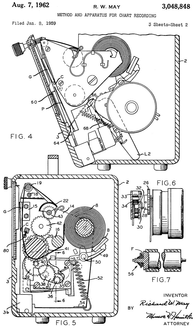
3048848 Method and apparatus for chart recording, Richard W May, Rust Ind, 1962-08-07, -
3129998 Controlling recording devices, Samuel K Lackoff, Rustrak Instrument Co, 1964-04-21, -
3170754 Adjustment of recording devices, Pincus Seymour, Rustrak Instrument Co, 1965-02-23, -


Harris TS-100 TDR
6856138 Time-domain reflectometer for testing terminated network cable, 2002-07-23 - uses two Zo values so it can see length of properly terminated line
Related
RiserBond 1205T Metallic Time Domain Reflectometer
This is a digital version of the Tek analog instrument.
Links
Modification to allow computer parallel port bit to start waveform output so and A/D can be used.
Guy Serbin's TDR page -
A Mostuure Sensing Cone Penetrometer (ASAE S313.1) - for measuring soil moisture
Sphere Research Test Equipment Site - CRT p/n 154-0667-02 normal P31 phosphor
New Developments in TDR Cable Survalience of Potential (soil) Instability -