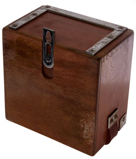
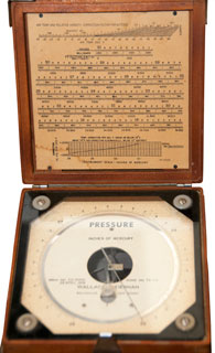
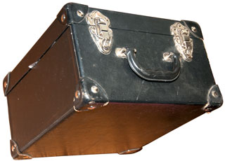
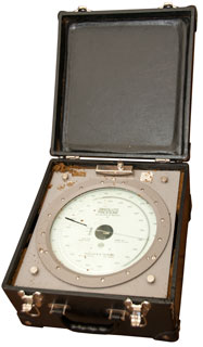
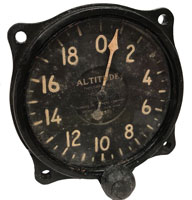
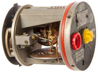
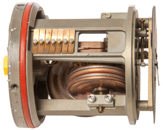
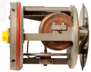
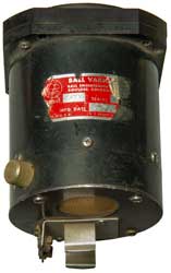
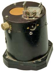
Wallace & Tiernan FA 181 Altimeter
Barometers & Altimeters
Aneroid
© Brooke Clarke 2018 - 2023
|
|
 |
Barometers
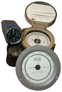
Wallace and Tiernan FA 160
Photos
Wallace and Tiernan FA 112
Photos
Wallace and Tiernan FA 129
Photos
Pressure Altimeters
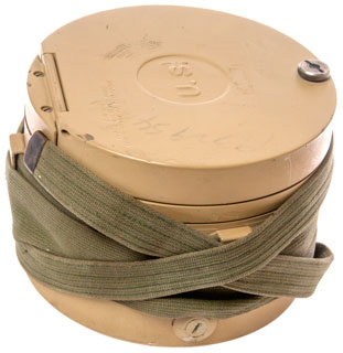
FA 181 Topographic Survey Altimeter
Operation
Calibration
Description
Photos
Patents
Manuals
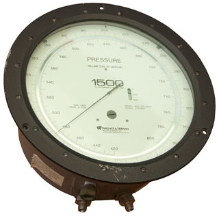
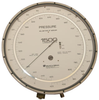
Wallace and Tiernan 1500 Gauge Model 62A-4D-0800
Description
Models
Photos
Kollsman Aircraft Altimeter TSO-C10b & Alti-Coder D39051-10-226
Description
Kollsman Patents
Pitot Tube
Servo Patents for High Altitude
Kollsman C-12 Altimeter
Kollsman AN 5760 Altimeter
Kollsman Altimeter Numerical Counter
Photos
Kollsman Machmeter
Airspeed Indicator
MS28046-W1 Airspeed Indicator
Generic Airspeed Indicator
Electronic Altimeter
APN-1 Altimeter
SCR-718 Radar Altimeter
Doppler Navigation RADAR
Ryan Aeronautical
APS-13 Airborne Tail Warning RADAR
Pressure Sensitive Switch
Rate of Climb
Ball Model 500
Miscellaneous
Related
References
Links
Background
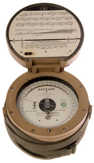
I started this page because I wanted a quality Altimeter (Wiki), and got the Wallace and Tiernan FA-181 altimeter. The Kestrel 5500FW Fire Weather meter has an altimeter function as does the Suunto watch.That led to also looking at Barometers (Wiki), since they are the same instrument just with different calibration marks. That led to other instruments that also depended on Aneroids (Wiki). Aneroids are also known as a capsule or diaphragm. They typically are made with a vacuum sealed inside and at sea level the air pressure causes the two sides to be closer to together than when the pressure is lower. But it's also possible to provide a fitting that allows the inside of the capsule to be connected to a tube so that it can be used to measure differential pressure. These are different from Bourdon tubes (Wiki).
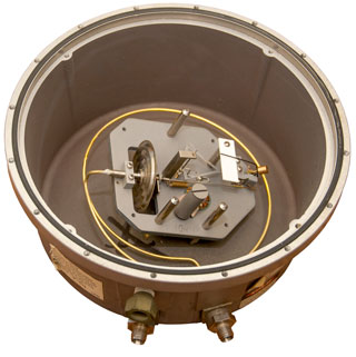
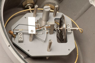
The Wallace & Tiernan company started out making water chlorination (Wiki) equipment invented by Charles Frederick Wallace based on using Chlorine gas. Part of that was the need to have a gas pressure gauge that operated with small negative pressures, so conventional barometers and altimeters were not suitable so they invented ones that would work. One aspect was to enclose the Aneroid barometer (Wiki) movement in a box and provide a fitting on the box as well as a fitting on the bellows (Wiki) so that differential pressures could be measured. The other improvement was to make the gauge more sensitive so it could measure the low pressures involved.
The resulting meter turns out to be a very good barometer/altimeter and these were purchased by various surveying outfits, typically for government topographic surveying since they cost more than the typical barometer/altimeter. The FAA also specified them for, I'm guessing, use at airports to measure the barometric pressure so pilots can set the runway pressure in their altimeters (Wiki), which can be done while the plane is the the air approaching the airport based on the invention of the "Kollsman window" type altimeter.
In addition to the gas pressure meters made for barometer/altimeter applications they also made versions for all kinds of gas pressure applications, both absolute, gauge and differential. One of the features is that the pointer can move more than 360 degrees by means of an index that signifies which range the pointer is one. Most have two ranges with a total angle a little less than 720 degrees, but that are some that have maybe 5 turns of the pointer.
Wallace & Tiernan company also made Radiosonde equipment used as part of weather data.. The key piece would be the altimeter mechanism that goes aloft, but also the ground equipment to demodulate the data from the sensors.
Barometers
Barometers (Wiki) measure the pressure of the air column above the instrument.
Wallace and Tiernan FA 160
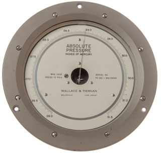
Aneroid type with a range of 26.0 to 31.5 inches of Mercury with minor tick marks of 0.02" Hg, i.e. readable to 0.01" Hg. The pointer moves less than one turn.
Marked:
Inches of MercuryMax. Case Press. 15 PSIG Serial No. ________ FA 160_NN12669
Wallace & Tiernan
Belleville, New Jersey
Photos
Fig 1
Fig 2
Fig 3 Group photo
Wallace and Tiernan FA 112
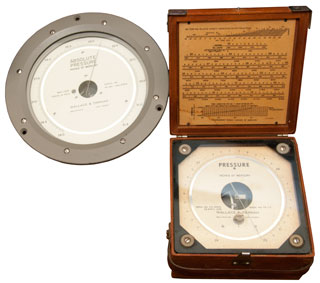
26 to 29" Hg less than one turn, very similar to the FA 160 above. The span is only 3" and the smallest graduation is 0.01" can be read to maybe 0.002" Comes in a wooden box that can be hung on a wall with compensations tables under lid.
This unit is not listed in the table of FA model numbers, it covers a more restricted range of pressures.
The pressure range seems to no go high enough for today's reading which is around 29.2" Hg but that's past the 29.0" max scale reading.
Why the low maximum scale limit? let me know. A guess for an airport, like Denver that will never see pressure higher than 29"?
Note I live at about 1000' above sea level and yet for the past week or so (late May early June 2018) the pressure has been above 29".
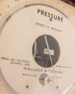
The serial number is DH00001, maybe Denver Height?
Photos
Fig 1 Note the FA160 reads 29.20" Hg and the FA 112 reads
a little less than 20.1 (off scale so just an estimate).
Fog 2 You can just see the capsule to the right
and the pointer gear wheel with a finger over it
to prevent the gear from disengaging if the
unit receives a mechanical shock.
date: 28 April 1978
Fig 3 Sliding hook for hanging on wall
Fig 4 tables in lid:
Air temp & Hum correction for altitude
Inches, millibar, Ft. Alt. per Smithsonian Meteorological Table 51
(zero = -1000 feet)
Temp correction from 75 def F (serial DH00001)
Wallace and Tiernan FA 129
0 to 800 mm Hg in two turns absolute pressure gauge.
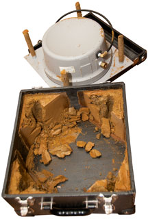
Got good price because the internal foam has disintegrated. Thinking how to replace it.
Photos
Fig 1 13" x 13" x 8"
Fig 2
Fig 3
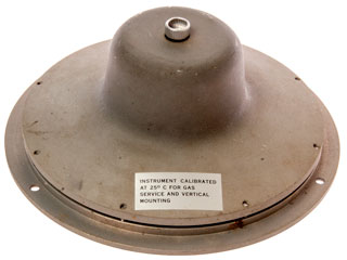
Fig 4 The FA160 flange 8.5" diameter is slightly smaller than the glass on the FA 129.
Pressure Altimeters
These (Wiki) are just barometers calibrated to read altitude. "The calibration of an altimeter follows the equation
where:
c is a constant,
T is the absolute temperature,
P is the pressure at altitude z, and
Po is the pressure at sea level.
The constant c depends on the acceleration of gravity and the molar mass of the air. However, one must be aware that this type of altimeter relies on "density altitude" (Wiki) and its readings can vary by hundreds of feet owing to a sudden change in air pressure, such as from a cold front, without any actual change in altitude."
The density altitude (Wiki) can be measured directly, for example see 4263804 Apparatus for directly measuring density altitude in an aircraft, Robert A. Seemann, 1981-04-28 - which works by measuring the power consumed by a motor turning a paddle wheel.
FA 181 Topographic Survey Altimeter
Operation
When the lid is closed and the rubber stopper-slide on the lid is in the Vent closed position then the vent is closed, otherwise the vent is opened. It should be closed whenever a measurement is not being made to keep moisture out of the chamber.
Unscrew the lid and, while looking where the pointer is going to be, quickly open the lid. You can see the pointer move tens of feet. So far it's always been between 16 and 18 (1600 - 1800 feet dial, or 600 to 800 feet actual) and always there is movement.
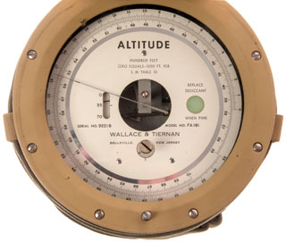
This particular unit is marked "Hundred Feet" so when the pointer is at 17 the indicated altitude is 1700 feet. But . . . it is also marked "Zero Equals - 1000 ft. per S.M. Table S1" so you need to subtract 1000 feet from the dial to get the actual reading. So in this case 1700 - 1000 = 700 feet elevation. That allows for elevations up to 1000 feet below sea level to be measured.
The displayed range is 0 to 3500 to 7000 feet with an elevation range of -1000 to 2500 to 6000 feet above sea level.
Calibration
Now that it's clear how to read the dial [ (100 * dial) - 1000 = elevation in feet] the next step is to calibrate it. Maybe the runway elevation at the local airport would be good for that.
Description
W&T data sheet 610.100 lists the following (i.e. they are closely related). All have 6" dials and weight between 3 and 4 pounds. Standard dial calibration units are inches of Hg.FA Model Numbers
FA-112 FA-139 FA-160 FA-185
Mounting
Panel
Panel
Panel
Portable
Range
13 to 30.5" Hg (18.5" span)
FA-112160
22 to 31.5" Hg (9.5" span)
FA-112150
19 to 32" Hg
FA-112170
26 to 29" Hg (3" span)
FA 112 boxed
28 to 31" Hg FA-139220
Altimeter Setting Indicator
660 to 800mm Hg FA-160180
or 26 to 31.5" Hg FA-160420
22 to 31.5" Hg FA-185260
13 to 30.5" Hg FA-185300
Accuracy
0.1% of full scale
0.3% of full scale 0.33% of full scale 0.1% of full scale Sensitivity
0.01% of full scale 0.02% of full scale 0.2% of full scale 0.01% of full scale Scale Length
35" through
2 pointer revolutions
17" through
1 pointer revolution16" through
1 pointer revolutions30" through
2 pointer revolutionsMinimum graduation
0.02"
0.01"
0.5mm or
0.02"
0.02"
FA160 0 to 2.0 inches Hg
FA160 0 to 120 inches Hg
FA160 0 to 40 inches Hg
FA160 0 to 800 mm Hg
FA160 RR12158 0 to 100 mm Hg abs
FA160 13,000 to -1500 feet 8.5" dialFA185 0 to 3,500 to 7,000 feet 5"? dial
From booklet Altimetry Manual and Operating Instructions for W & T Surveying Altimeters, Instruction Book No. FIA-112-1-3, 1953.
The types FA-112, FA-181 and FA-185 all have the same mechanism, and dials approximately 5" in diameter. The scale is about 29" long over almost two revolutions. Reference is made to the Smithsonian Meteorological Table (SMT) 51 in regard to the Zero equals 1000 feet notice?
The FA-176 is a more sensitive instrument having a narrow range of -500 to 1500 feet per SMT 51 (-150 to 500 meters) with graduations of 5 feet.
FA176 19 to 21.5 to 24 Pounds 8" glass portable 11-3/8" overall dia
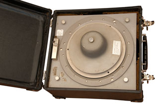
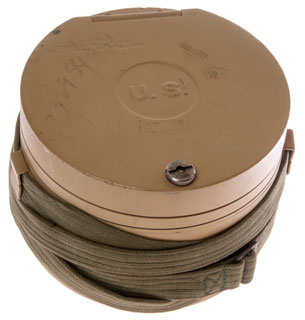
The FA-181 is a military model with it's round aluminum case also serving also as the carrying case. The lid may be removed for wall mounting the instrument. (two "_" screws hold the lid on).
FA181 0 to 3,700 to 7,000 feet 4"? dial
FA181 0 to 550 to 1,200 meters (zero = -300 meters), portable
The FA-185 has a round aluminum case with no lid. The leather carrying case with hinged lit is provided.
In the FA-112 the window closure is dust tight but not air tight.
Each dial is individually calibrated for its particular mechanism. Each dial and mechanism is marked with a serial number and they are not interchangeable.
From a sampling of eBay ads.
FA129 0 to 400 to 800 mm Hg 8-1/2" dial
FA129 0 to 400 to 800 mm Hg 8-1/2" dial
FA129 0 to 16.5 to 32 PSI 10-3/4" flange
FA129 0 to 50 to 100 inches Hg absolute 10-3/4" flange
FA129-MM15679 0 to 36 to 70 Abs cabin pressure PSIG
FA141 Liquid Oxygen ?
FA141 0 to 20 inches H2O
FA141 0 to 10 inches H2O 8-1/2" dial
FA141 0 to 800 mm Hg
FA141 0 to 800 mm Hg
FA141 0 to 800 mm Hg
FA141 0 to 500 PSI Liquid Oxygen
FA141 0 to 10 PSI
FA141 MM11336 0 to 20 inches H2O 3-3/4" flange
FA141 0 to 20 inches H2O vacuum
FA145 0 to 90 to 300 inches Hg
FA145 0 to 490 to 1,000 mm Hg
FA145 0 to 1,900 to 5,000 #/sq ft
FA145 -30 to +40 to +170 inches Hg
FA145 -100 to +10 to +2,400 inches H2O
FA145-NNI5600 3 to 15 PSIG (0 to 100 %) 10-3/4" flange
FA145 0 to 6.5 to 15.0 PSIG N2
FA145 0 to 54 to 120 inches H2O
FA145- MM19248 0 to 5.0 to 10.0 PSI
FA145-MM11329 -100 to 10 to 24 inches H2O 10-3/4" flange
FA145-NN15924 0 to 20 inches H2O 8-1/2" flange
FA145-MM13503 0 to 46 to 90 inches Hg
FA-145 Calibrator 0 to 215 to 430 inches H2O small box with controls
FA145-MM13503 0 to 46 to 90 inches Hg
FA145-CC12151 o to 18 to 35 PSI
FA149 Monostat Pressure Regulator - hand wheel at top sets pressure/vacuum
FA149 Monostat Pressure Regulator - hand wheel at top
FA193 no pointer, just electrical switch (5 mm Hg) box options: Barometer, Altimeter, Contactor (checked), Pneumatic Calibrator, Monostat
FA199 0 to 1400 to 2550 to 3600 to 4800 meters altitude, portable (4 turns, unlike others which are 1 or 2 turns) (FS-199, not FA-199) TM 5-6675-203-15
FA233 0 to 100 to 200 PSI
FA234-PP16919 0 to 150 to 300 PSIG
FA-234-PP14681 0 to 150 to 300 PSIG 10-3/4" flange
FA181000 0 to 1,000 to 2,100 meters
FA193111 no pointer, just electrical switch 11746 mm ?
FA193161 no pointer, just electrical switch
FA-193121 no pointer, just electrical switch, NSN 5930-806-5756
65-120 Pneumatic Calibrator -23 to 14 to 30.6 inches H2O
65-125 like the 65-120 except digital pressure gauge
Photos
Fig 1 Case Closed
Fig 2 Case Open

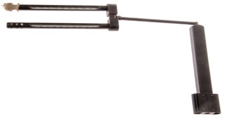
Fig 3 Door open showing screwdriver & Sling Psychrometer
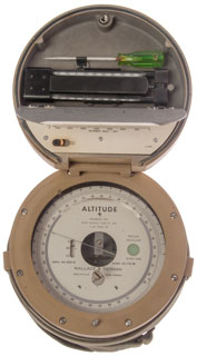
Fig 4 Back with hanging "d" hole.
Should be read with dial/back vertical, not laying on table.
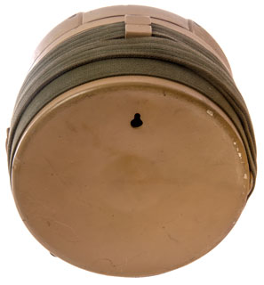
Fig 5 Sling Psychrometer (Wiki)
Fig 6
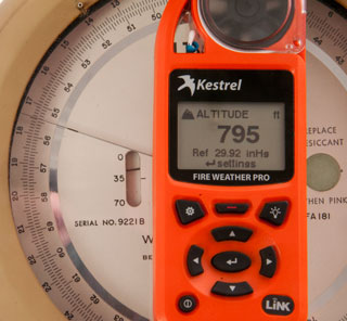
Fig 7 Compare to Kestrel 5500FW
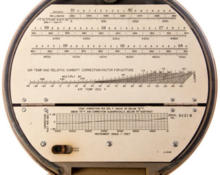
Fig 8 Corrections imply accuracy to better than 5 feet.
Top: convert altitude to pressure
Center: Air Temp & Relative Humidity corrections
Bottom: Custom temperature correction for this particular instrument.
Fig 9
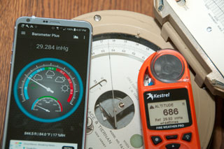
Comparison:
Android
Barometer Plus
FA-181
Kestrel
5500FW
29.284"
na
29.92"
848.5'
((100* 16.5)-1000) = 650'
686'
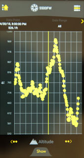
Fig 10 Altitude variation from Kestrel 5500FW
550' to 980' variation due to weather.
I don't have a feel for how much to expect.
Fig 11 Two screws at left to remove lid for wall mounting.
Bottom center desiccant access hole.
"Caution, Close Breather Tube, for Storage or Transport"
Fig 12
Patents
A note on patent dates
When something that might be of use to an enemy in time of war the patent publication is delayed. My guess is that the amount of delay is proportional to how big a secret it is. When you see two dates, such as 1941-09-24 (Pub: 1945-02-06) it means the patent was filed in 1941, just prior to W.W.II for the US, but only published near the end of W.W.II. In other cases I've seen delays of 20 to 30 years, for example see China Lake Patents.
2603973 Flexible chamber pressure gauge, Charles F Wallace, Wallace and Tierman Inc, 1947-03-15 (Pub: 1952-07-22) - 2 fittings & other improvementsWallace and Tierman
Wallace and Tierman have about 647 patents, so not all of them are here. AFAICT (Wiki) the company started out making water chlorination equipment and beacon lights for marine and airports where reliability was very important. The water chlorination system that uses Chlorine gas requires precision measurement of small negative pressures necessitating the invention of an improved gas pressure gauge. They also got into process equipment relating to products based on Chlorine, probably because it's a toxic gas and proper handling was one of their skill sets. They are now part of a company that does water treatment but does not seem to make barometers or altimeters. http://www.evoqua.com/en/brands/Wallace_and_Tiernan
The inventor is listed as C.F. Wallace on most of these patents which makes me think he was not really the inventor but rather the president of the company. I can understand how he may have made the initial inventions but don't see how he could have made inventions is such different subjects.
1553294 Shortening compound, John C Baker, Wallace and Tierman Inc, 1921-09-02 - for pie crust: fat, water, Sodium stearate & stearic acid emulsed at 3,000 PSI.
1587050 Electrical indicator, Harry L Tanner, 1922-04-13 - zero center bi-polar indication, not full circle
1593109Chemical dosing apparatus, Charles F Wallace, Wallace and Tierman Inc, 1924-03-06 - water chlorination
1678625 Apparatus for the therapeutic application of chlorine,Charles F Wallace, John C Baker , Wallace and Tierman Inc, 1924-06-18 - diluting Chlorine gas in air for respiratory therapy.
1741590 Electrical indicating instrument, Harry L Tanner, Tanner Engineering Co, 1926-04-26 - an early 3-wire synchro?
1794134 Colorimeter,Charles F Wallace, John C Baker , Wallace and Tierman Inc, 1926-06-08 - for comparing color of liquids.; 2341810;
1834759 Rubber printing plate, John C Baker, Wallace and Tierman Inc, 1928-03-24 - improvement made with backing plate in the same step
1841341 Means for producing indications, H.L. Tanner, 1923-11-17 - electrical meter movement, soft iron vane on bottom of needle pulled to bipolar electromagnet.
1850975 Method of making hypochlorite solutions, John C Baker, Wallace and Tierman Inc, 1927-04-11 - a method of making hypochlorite (Wiki) solutions
1878076 Electrically energized motor, Charles F Wallace, Wallace and Tierman Inc, 1929-03-07 - The Self Winding Clock Co. was doing this in 1877
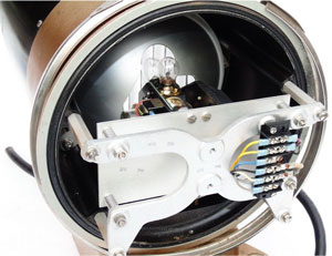
1955616 Signal device, Charles F Wallace, Wallace and Tierman (sic) Inc, 1927-08-29 - Marine or Aircraft Fresnel Signal light with 6 lamps to come into place as the active lamp burns out; 2051506; 2289315; 2342085; 2551029; 2551028; on eBay listed with key words: Wallace Tiernan 24 inch ship boat light (the cylinder is about 8" dia.)
you can see the top of the wheel of lamp bulbs.
1964227 Telemetric system, H.L. Tanner, Wallace and Tierman Inc, 1928-05-26 - an early 3-wire synchro?
1986308 Weighing apparatus, Charles F Wallace, Wallace and Tierman Inc, 1928-12-14 - circular paper disk records weight vs. time
2016257 Process of manufacturing n-chloro-azo-dicarbonamidines,Franz C Schmelkes, Henry C Marks , 1934-03-17 -Bactericide (Wiki)
2022747 Incandescent lamp,Sovulewski Lawrence Gabriel, Booth George Martin, 1934-07-06 - filament is vertical line for use in Fresnel lens (Wiki) systems
2233372 Method for testing dough, John C Baker, Wallace and Tierman Inc, 1938-05-21 -
2306819 Sound signal apparatus, John R Mackay, Wallace and Tierman Inc, 1938-03-14 - electromagnetically driven fog horn: GB526250;
2340279 Recorder, Charles F Wallace, Wallace and Tierman Inc, 1940-12-26 (Pub: 1944-01-25) - time interval type to work with Radiosonde; 2354086;
2347160 Radiometeorograph transmitting apparatus, Charles F Wallace, Wallace and Tierman Inc, 1940-04-04 (pub: 1944-04-18) - Radiosonde; 2340718; 2352578;
2347345 Radiometeorograph transmitting apparatus, Wallace Charles F, Wallace & Tiernan Inc, Apr 25, 1944, 340/870.1, 340/870.12, 340/870.16, 188/185, 200/56.00R, 340/870.13, 73/170.28 - Temperature, pressure, relative humidity; see Radiosonde
2361723 Pressure-responsive meter apparatus, Charles F Wallace, Wallace and Tierman Inc, 1940-01-31 -"This invention relates to detecting, recording and indicating means and procedure, notably of pressure-responsive type, and designed, for example, to detect and record gas flows handled under small pressures, particularly small negative pressures." For water chlorination system.
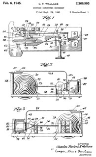
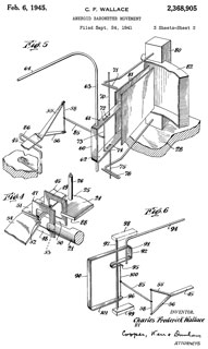
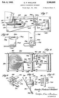
2368905 Aneroid barometer movement, Wallace Charles Frederick, Wallace and Tierman Inc, 1941-09-24 (Pub: 1945-02-06) - maybe for use in Radiosonde?
2418379 Apparatus for establishing a vacuum in manometer-type instruments, Charles F Wallace, Wallace and Tierman Inc, 1944-09-14 (Pub: 1947-04-01) - filling mercury barometer
GB601589 Improvements in or relating to apparatus for indicating and/or recording small relative displacements in aneroid barometers, altimeters and similar instruments, Wallace and Tierman Inc, 1941-09-24(same as US2368905) (Pub: 1948-05-10) -
2368905 Aneroid barometer movement, Wallace Charles Frederick, Wallace and Tierman Inc, 1941-09-24 (Pub: 1945-02-06) - (Wiki) greatly improving the sensitivity and fidelity of response..."...to provide an instrument which immediately responds to atmospheric or like pressure changes, without the need for tapping or other agitation..."
GB617063 Improvements in or relating to aneroid type instruments responsive to ambient gaseous pressure,Wallace and Tierman Inc , 1944-01-07 (Pub: 1949-02-01) -
2385468 Monoalkyl ethers of diethylstilboestrol, Reid Ebenezer Emmet, Wallace and Tierman Inc, 1940-06-25 - (Wiki)
2391060 Recording and indicating system, John R Mackay, Wallace and Tierman Inc, 1939-03-14 - for water chlorination system
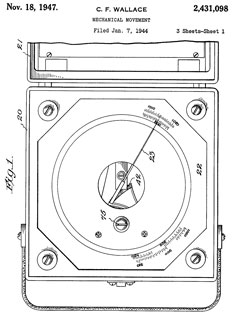
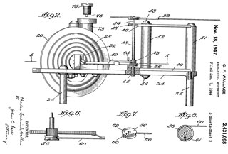
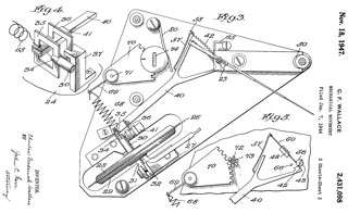
2431098 Mechanical movement, Wallace Charles Frederick, Wallace & Tiernan Produets Inc, 1944-01-07 (Pub: 1947-11-18) - improvement on 2368905, provide more sensitive, more accurate and simplified structure for aneroid barometer movements
Calls Kollsman 2150771
2585060 Electrical cell apparatus for testing liquids, Charles F Wallace, Wallace and Tierman Inc, 1948-03-05 - "...
determination of active chlorine, particularly residual chlorine such as may be present in water, sewage or other aqueous liquid that has been subjected to chlorine treatment, e. g. for purification."
2599956 Absolute pressure controlling apparatus,
Charles F Wallace, John O Kirwan, Wallace and Tierman Inc , 1946-06-08 (Pub: 1952-06-10)-
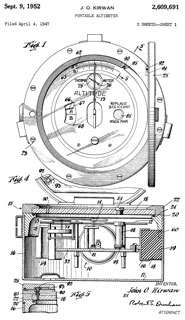
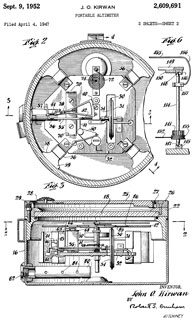
2609691 Portable altimeter, John O Kirwan, Wallace and Tierman Inc, 1947-04-04 (Pub: 1952-09-09) -
Intended for topological surveying rugged, portable, accurate, precise
Manuals
FIA-112-1-2 Altimetry Manual and Operating Instructions for W & T Surveying Altimeters, Instruction Book FIA-112-1-2, 1952, Form No. 2232-1 (FIA-112-1-2.pdf)
This booklet covers: FA-112, FA-176, FA-181, FA-185FIA-112-1-3 Altimetry Manual and Operating Instructions for W & T Surveying Altimeters, Instruction Book FIA-112-1-3, 1953, Form No. 2232-1
The References page adds: 8. Altimeters as used by The 30th Engineers for Mapping. (Wallace & Tinerman Technical Reprint RA-2004-A) 1952
This booklet covers: FA-112, FA-176, FA-181, FA-185TM 5-6675-203-15 (this is for a similar instrument, not the FA-112, FA-181)
Enclosed W&T letter November 16, 1954 - includes a superseded Air Temp & RH Correction chart (but no serial No. temp data).
TO 49A3-6-1
Operator, Organizational, Field and Depot Maintenance Manual Including Repair Parts and Special Tool Lists,
Altimeter, Surveying
4,500 Meters
2 Meter Divisions
(Wallace and Tiernan Type FA-199)
FSN 6675-641-3569
Departments of the army and the Air Force
October 1960
FM 6-2 Artillery Survey, Aug 1965 has some information on the FA-199 in Chapter 11. Altimetry.
TM 5-235 (archive) Special Surveys, 1940 (1953)-
------------------ from internet archive ------------ reformatted to make sense -----
TM 5-9418 Altimeters, surveying, 15,000-ft, 20-ft divisions, type 15 Wallace& Tiernan Model FA-113, 31 Mar 44
TM 5-9420 Altimeter, surveying, 6000-ft, 10-ft divisions type 6, Wallace &Tiernan, Model FA-112, 31 Mar 44
TM 5-9421 Altimeters, surveying, Wallace & Tiernan Models FA-112, FA-113, and FA-181, 28 Dec 51
TM 5-9422 Compass, sun, universal type, Abrams Model SC-1. 4 Aug 43 (It's interesting that the Sun Compass shows up next in the list.)
Wallace and Tiernan 1500 Gauge Model 62A-4D-0800
Description
This is a differential pressure gauge 0 to 800 mm Hg in steps of 1 mm.
The dial is calibrated for 0 to 400mm (15.75") to 800 mm (31.5") Hg. Note that the standard atmospheric pressure at sea level is:
760 mm Hg or 29.92" Hg or 1013.25 milliBar. As the altitude gets higher the absolute air pressure decreases and in outer space would be zero.
Another way to say that is this is an aneroid barometer (Wiki).
Note as received pointer is on 35 mm Hz, not 760mm. The small dial is near 220 mm Hg not anywhere near almost to 800 mm Hg.
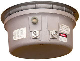
I got it for a very low price since there appears to be a mechanical problem. The fittings are 1/8" pipe thread.
Notice that dial reads CW for increasing pressure (lower right connection) or increasing vacuum (lower left connection). The FA-181 dial reads CCW for increasing altitude.
Models
61-050 Absolute Pressure
62-050 Guage/Compound Pressure
62-075 Differential Pressure
65-120 Precision Pressure Calibrator - external air supply
DP-150 Precision Pressure Calibrator - with hand pump
Photos
------------------------------------------------------------------------------------------------
Kollsman Altimeter TSO-C10b & Alti-Coder D39051-10-226
Paul Kollsman worked for Pioneer Instrument Co. (Wiki) but left to form his own company when Pioneer did not want to peruse his altimeter idea. They already made an instrument with a simple dial marked 0 to 18 (thousand feet), i.e. supposedly worked 0 to 20,000 feet. eBay search "Pioneer Instrument" Pioneer was absorbed by Bendix (Wiki). But. . . I don't see any patents with Kollsman working at Bendix.
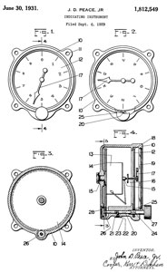
1812549 Indicating instrument, Jr John D Peace, PIONEER INSTR CO Inc, 1929-09-06 -
RE19709 Indicating instrument, Jr John D Peace, PIONEER INSTR CO Inc, Sept 17, 1935 -
Not only did Kollsman work for Pioneer, but so did Victor E Carbonara who worked on the MD1 Star Tracker -
while at Pioneer he invented one of their sextants:
1970543 Navigating instrument, Victor E Carbonara, PIONEER INSTR CO Inc, 1934-08-21 - Bubble Sextant, Mark III Model 3
Paul Kollsman (Wiki) founded the Kollsman Instrument Co. There was a Kollsman.com web page but it seems to be offline (Archive Elbit Systems).
I'm guessing the altimeter has an analog output and the Alti-Coder converts that into some type of digital signal that could be fed to an ADS-B transponder (Wiki) and/or a data buss such as MIL-STD-1553 (Wiki). Also guessing that more modern aircraft altimeters have the Alti-coder function built-in rather than use two devices.
NYT 1982: Paul Kollsman, 82, Aviation Engineer -
I asked the FAI how they determined aircraft altitude record elevations and the answer was: "Control methods for past records have been done with calibrated altimeters and some with radars. But we do not have an historical resume for them."
Kollsman made the periscopic aircraft sextant.
Description
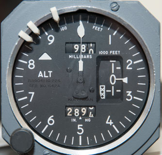
The altimeter label:
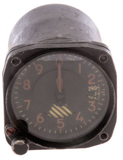
Altimeter, Pressure Corrected Type, Integrally Lighted, 5AVC 0.68 Amp, Range -1000 to +50000 Feet, FAA TSO-C10b, Kollsman Instrument Corporation, Elmhurst New York
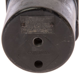
There are Aero Instruments service stickers on both instruments.US Patents
2689480 (see below)
3009358 (see below)
3043580 (see below)
2851002 (see below)
3040168 (see below)The Alti-coder label:
Alti-Coder, Type No. D3841000201, Serial No. 1757, Kollsman Instrument Corporation, Elmhurst New York.
US Patents
3242737 (See Below)
Photos
Fig 1
Fig 2
Fig 3
Fig 4 Knob used to set altitude to zero elevation, i.e.
"Manual Barometer" operation. The barometer reads:
980 millibar or 28.945" Hg.
-----------------------------------------------------------------------
Kollsman Patents
Kollsman holds many patents for the Periscopic Sextant. as well as patents for the MD1 Star Tracker.
They also have Great Britain and Canadian patents, not listed here.Paul Kollsman invented the idea of a "setting" (Wiki) on an altimeter so that variations in the barometric pressure caused by weather can be backed out of the altitude reading. This setting is refereed to as the "Kollsman Window" (Wiki). The Wiki article on Paul says he founded the company in 1928, most of the patents do not show the company name.
The early altimeters were pretty much just barometers with the dial face marked in altitude assuming a sea level pressure of 29.92" Hg. This means that they have an error caused by the barometric pressure changes related to the weather. In 1931 the "Kollsman Window" type altimeters where the pilot can set the barometric pressure for the runway where he wants to land were introduced. Now the elevation shown on the dial should match the known elevation of the runway.
The next problem was with the pressurized aircraft flying above 15,000'. The air is much thinner and so there was not enough force from the aneroid capsule to work the mechanism.
P-80 jet fighter (Wiki) introduced 1944 - cruise ceiling: 46,000 feet.
B-45 Bomber (Wiki) introduced in 1947 was the first U.S. jet bomber. service ceiling: 46,000 feet.
Wiki-Flight Altitude Records by year - prop planes: 1890 to 1938. It's questionable how the height was determined in those days.
The "Kollsman Servoed Altimeter" of 1947 fixed this problem by using a motor and null detecting mechanism to drive the pointer. But these do not work without external electrical power, i.e. they fail when the electrical system fails. Sold on eBay as "for parts" since the proper electrical power is not common.
1741702 Indicator, Kollsman Paul, 1929-08-06 - provision for setting a reference altitude (not shown as pressure). Weather barometers have a a range of 26.5" to 31.5" of Mercury. But that covers many variables.
1841606 Turn indicator, Kollsman Paul, 1929-06-25 -
1841607 Turn indicator, Kollsman Paul, 1929-06-25 -
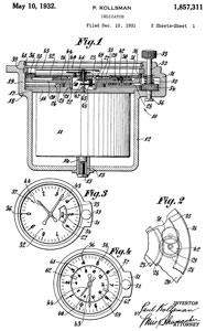
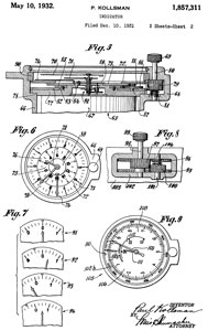
1857311 Indicator, Kollsman Paul, 1931-12-10 - provision for setting the landing strip elevation so the altimeter indicates height above ground.
RE18306 Indicator, Paul Kollsman, Dec. 29, 1931 - Re-Issued
RE19079 Altimeter, Paul Kollsman, Feb. 13, 1934 - Re-Issued
RE20948 Quick Reading Altimeter, Paul Kollsman, Dec. 13, 1938 - Re-Issued
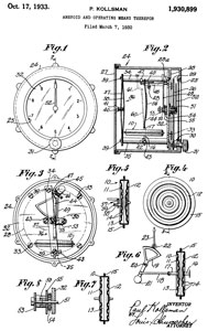
1930899 Aneroid and operating means therefor, Kollsman Paul, 1930-03-07 - temperature compensation is external to the capsules.
See: 2150771 where the temperature compensation is built into the capsule
Used on F-4 airspeed indicator
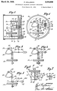
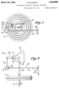
2034909 Universally balanced aircraft indicator, Kollsman Paul, 1931-03-18 -all transnational forces are balanced so they do not effect the pointer. But rotational forces do effect pointer, especially rocking in the for-aft plane, i.e. pitching.
2041072 Magnetic compass, Kollsman Paul, 1933-07-22 - compensation for the variation of fluid density with temperature by making a part of the float match the liquid density.
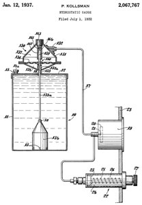
2067767 Hydrostatic gauge, Kollsman Paul, 1932-07-01 -
The 1934 Rolls Royce Phantom II uses this type of gas gauge where a pump is used.
2052409 Indicator, Kollsman Paul, 1934-06-18 - Bourdon tube (Wiki) temperature gauge with remote probe.
2067767 Hydrostatic gauge, Kollsman Paul, 1932-07-01 -
2078574 Compensating device for magnetic compasses, Kollsman Paul, 1933-04-20 - maybe Aircraft Pilot's Standby Compass?
2080490 Remote controlled indicator with stabilized head, pitch, and bank indicating unit, Kollsman Paul, 1932-04-05 -
2088559 Miniature electric lamp bulb seat and socket combination, Kollsman Paul, 1937-05-01 - grain of wheat bulb in metal screw-in holder.
2100604 Instrument mounting, Kollsman Paul, 1935-03-05 - maybe the standard aircraft panel instrument with 4 mounting screws.
2140704 Temperature compensator for pressure responsive devices, 1935-09-30 - temperature compensation (See Pressure Altimeters above for equation that includes absolute temperature)
2161870 Automatic means for varying compass card oscillation, Kollsman Paul, 1933-05-17 - improved dampening
2171431 Miniature lamp instrument illuminator system, Kollsman Paul, 1937-10-15 -
2172765 Indicator illumination, Kollsman Paul, 1934-04-05 - grain of wheat bulb in metal screw-in holder.
2150771 Self-compensating aneroid, Kollsman Paul, 1934-12-17 - Temperature compensation between sea level and 30,000 feet.
2154273 Method of and apparatus for making aneroids, Kollsman Paul, 1933-05-15 -
2219243 Gyroscopic instrument, Kollsman Paul, 1939-06-08 - gyroscopic stabilized magnetic compass
-----------------------------------------------------------------------------------------------------------------------------------------
Pitot Tube
The Pitot tube (Wiki) is part of an aircraft Pitot-static system (Wiki) that consists of the pitot-static tube which feeds the airspeed (Wiki) indicator (Wiki), Vertical speed indicator (Wiki) and altimeter (Wiki) and Machmeter (Wiki) for faster planes.
For a 10 MPH wind the pressure difference is only 0.025" of water, a small number to measure, but doable.
The pitot tube will NOT work for flows that are supersonic.
Henri de Pitot (1695-1771) - Constructed double-tube device to indicate water velocity through differential head
Theory of operation -
Using a U-tuber manometer to measure fluid flow velocity -
Telescoping Pitot Tube - for HVAC ducts
Calibrate Your Airspeed Indicator - for aircraft Air Speed Indicators (with Excel spreadsheet)
NASA - Report No. 2 Investigation of Pitot Tubes. - includes: General remarks on Resistance anemometers, Wind resistance of flat plates, Bourdon-Venture Anemometer, Comparison of types of anemometer: Pitot tube, Pressure Plate, Bourdon-Venturi, Robinson (Wiki) (rotating cups).
Also see Aircraft Ref 48: Pitot-Static System and Ref 52: How a Tiny Hole Caused Dozens of Air Disasters
1971534 Pitot-static tube, Jr John D Peace, Bendix Aviation Corp, App: 1932-08-11, Pub: 1934-08-28, 73/861.68-
2042700 Pitot-static tube, Charles H Colvin, Pioneer Inst Co, App:1928-03-14, Pub: 1936-06-02, 73/861.68 -
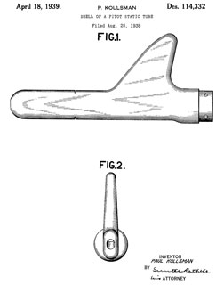
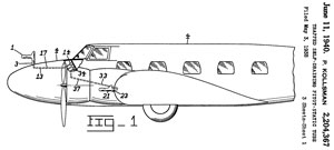
D114332 Shell of a Pitot Static Tube, P. Kollsman, Filed: Aug 25, Pub: April 18, 1939
Fig 1
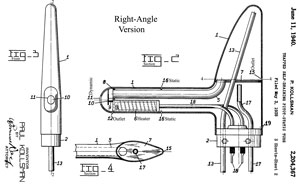
Fig 2 Right-Angle
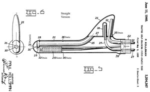
Fig 3 Straight
2204367 Trapped self-draining pitot-static tube, Kollsman Paul, 1940-06-11 -
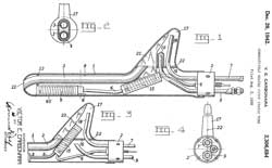
2306684 Conductively heated pitot static tube, Victor E Carbonara, (Square-D, then Kollsman), 1942-12-29, -
Fig 1
Fig 2
Fig 3

2203824 Directional instrument, Kollsman Paul, 1940-01-31 - Turn Indicator
2215447 Turn indicator, Kollsman Paul, 1937-07-30 - gyroscopic
2224732 Directional instrument, 1940-01-31 -
2232537 Remote controlled indicator with stabilized head, pitch, and bank indicating unit, Kollsman Paul, (no assignee), 1937-05-17 -gyroscopic
1146202 Anemometer, Alec Ogilvie, 1915-07-13 - diaphragm moves in proportion to the square root of the pressure making for a linear dial graduation - dynamic ram tube
1426698 Speed meter for aeroplanes, Albert F Zahm, 1922-08-22 - designed so water does not block Venturi (Wiki) & ram air tubes
3137158 Air density meter, Rudolph E Krueger, 1964-06-16 - 29.92" Hg & 59 def F = 100% - some gas sealed in the aneroid.
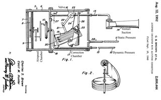
2606444 Air-speed indicator with altitude correction, Charles S Brown, Cecil M Hunter, Hunter Co, 1952-08-12 - air density changes with altitude and so needs to be compensated
---------------------------------------------------------------------------------------------------------------------------------------------------------------------------------------
Kollsman Servo Patents
This was done to get readings at high altitudes. As the height increases the force available to move the mechanism gets weaker and so quit working. To overcome this a servo mechanism was added.
In the book Spyplane: The U-2 History Declassified by Norman Polmar 2001 on page 59 (redacted version Utility Flight Handbook 1959)- about 1955 "When Johnson ordered altimeters from the Kollman (sic) Instrument Company he specified that the devices had to be calibrated to 80,000 feet. This immediately raised eyebrows at Kollman (sic) because its standard aircraft altimeters only went to 45,000 feet. Agency security peresonnel quickley briefed several Kollman (sic) officials and produced a cover story that the altimeters were to be used on experimental rocket planes."
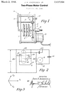
2437064 Two-phase motor control, Jr John H Andresen, Schneider Electric USA Inc, 1946-01-29
the gap between contacts (5) and (6) is changed by the motor running CW or CCW in response to changes in the length of the stack of three barometric capsules.
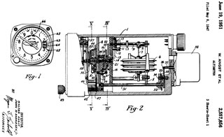
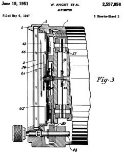
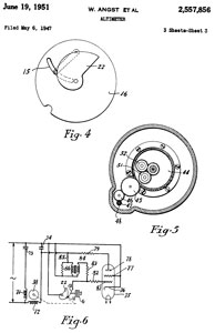
2557856 Altimeter, Angst Walter r, John H Andresen , KOLLSMAN INSTR CORP, 1947-05-06 -
at sea level a change of 100' = 0.1" Hg = 0.001" movement of the chamber/element/bellows/capsule
at 80,000' a change of 100' = 0.004" Hg = 0.00004" capsule movement
a motor is used with a spiral cam to sense the position of the capsule.
See 2437064 above for motor control.
2579902 Instrument for correlating air speed, angle of attack, and aircraft loading,Victor E Carbonara, Jr John H Andresen , KOLLSMAN INSTR CORP, 1945-08-04 -
2604117 High-power diaphragm capsule assembly, Angst Walter, KOLLSMAN INSTR CORP, 1949-07-02 - capable of driving two pointers with a 10:1 ratio.
2689342 Pressure operated switching device, Paul R Goudy, KOLLSMAN INSTR CORP, 1954-09-14 - radiosonde modulator system
2689480 Sensitive wide range altimeter, Angst Walter, KOLLSMAN INSTR CORP, 1950-04-15 - up to 80,000 feet (U-2) requires new techniques because of the very low pressure hence low forces available.
2701474 Pitot tube anemometer, Paul R Goudy, KOLLSMAN INSTR CORP, 1955-02-08 - multiple pressure tube anemometer, no moving parts exposed to ambient weather conditions
2829833 Azimuth Counter - moved to MD1 Astro Compass web page - not altimeter
2851002 Aircraft instrument-dual drum scale,Angst Walter, KOLLSMAN INSTR CORP, 1958-09-09 - inches of Hg on altimeter
"Kollsman Servoed Altimeter" (only works with external power)
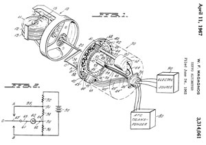
3314061 Servo altimeter, William F Magagnos, KOLLSMAN INSTR CORP, 1963-06-24 -
Air Traffic Control Transponder output (80), brush encoder disk (40), DC Motor (60)
Fig 2 is schematic of follow-up servo movement
2894392 One-way temperature compensation for pressure measuring instruments,Mclaughlin Robert, KOLLSMAN INSTR CORP, 1959-07-14 - only compensates when temperetue above some specified temperature, but not below that temperature.
Patents on labels
2689480 see above
2851002 Aircraft instrument-dual drum scale,, KOLLSMAN INSTR CORP, 1958-09-09 -
3009357 Aircraft instrument-remote control-fail safe,Jr John H Andresen , KOLLSMAN INSTR CORP, 1961-11-21 -
3009358 Aircraft instrument-remote control-fail safe, James W Angus, KOLLSMAN INSTR CORP, 1961-11-21 - Mechanical pointer continues to function even if electrical system fails, but not as accurate. Note in photos the altimeter is reading close to my elevation.
3040168 Instrument lighting device, Stearns Thornton, KOLLSMAN INSTR CORP, 1962-06-19 - instrument lighting glare reduction
3043580 Return mechanism for fail safe instruments, James W Angus, KOLLSMAN INSTR CORP, 1962-07-10 - like clock mainspring
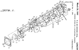
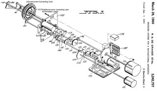
3242737 Encoding system for a navigational apparatus, Grande Robert S De, Baron Leonard, KOLLSMAN INSTR CORP, 1966-03-29 - all mechanical, not optical encoder?
------------------end of label patents-------------
3001503 Instrument dial, Hezel Herman, KOLLSMAN INSTR CORP, 1961-09-26 -
3009357 Aircraft instrument-remote control-fail safe, James W Angus, KOLLSMAN INSTR CORP, 1961-11-21
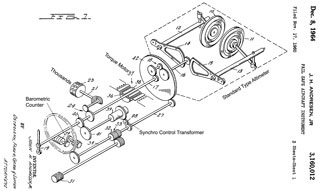
3160012 Fail safe aircraft instrument, Jr John H Andresen, KOLLSMAN INSTR CORP, 1964-12-08 -
3112644 Integrated flight instrument system, Everett H Schroeder, KOLLSMAN INSTR CORP, 1963-12-03
Combined airspeed-angle of attack indicator
Altimeter
Mach meter
True outside air temperature indicator
True airspeed indicator
Ram air temperature indicator
Scale error corrector for altimeter
Correction for static system errors due to angle of attack and Mach number
Angle of attack sensor
3206974 Integrated flight instrument system, John H Andresen, KOLLSMAN INSTR CORP, 1965-09-21 -
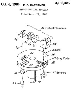
3152325 Hybrid optical encoder, Paul F Kaestner, KOLLSMAN INSTR CORP, 1964-10-06 - starting with a conventional Gray Code encoder then . . . "The present invention is directed to concurrently provide the fine readout and, at the same time, eliminate first order eccentricity errors in the optical disk." provides 16 bits from a 3" dia disk where prior art required a 9" disk.
Calls:
3046541 Angle digitizer, Lewis A Knox, IBM, 1959-06-29 - 1 arc second mechanical + Optical
3228246 Pressure measuring device, Lilly S Rosenthal,KOLLSMAN INSTR CORP, 1966-01-11 - interferometer or spectrometer using pure gas using pure gas
3262416 Altimeter structure, David B Nichinson, KOLLSMAN INSTR CORP, 1966-07-26 - instead of setting the pressure at the landing runway you set it's elevation.
3742325 Plural input mode servo driven air data computer, J Andresen, Intercontinental Dynamics Corp, 1973-06-26 - John Andersen is the same inventor that appears above on many Kollsman instruments. This is the first Air Data Computer (Wiki). The Alti-Coder is an intermediate solution.
YouTube:Bendix Air Data Computer - Part 2: Master Ken Explains (re-upload), 12:59 -
---------------------------------------------------------------------------------------------------
Kollsman C-12 Altimeter
p/n: 671BK-010
This is an all mechanical altimeter with the "Kollsman Window".
Label:
Type C-12
Mfrs. Part No. 671BK-01
Contr. No. AF-33186
Ser. No. AF 43-110537
U.S. Patent Nos. 1930899;
2034909; 2140704; 2154273;
RE.18306; RE.19079; RE.20948
Patented Canada 1933, 1937
Kollsman Instrument Division
of Square D Company
Elmhurst New York
This is a Radium dial instrument (Wiki) from the 1910 to 1935 time period. See Fig 3 below for a UV light photo. Note Navy aircraft flying in the late 1950s used UV lights to flood the instrument panel and caused the instrument pointers and markings to glow, yet left the cockpit dark so when flying at night the pilot's eyes stayed night adapted.
Photos
Fig 1
Fig 2
Fig 3 UV light photo. Note big numbers and hands are not glowing. Almost certainly a Radium glow in the dark dial (Wiki) from the 1910 to 1935 time period.
---------------------------------------------------------------------------------------------------------
Kollsman AN 5760 altimeter
This looks like it might be for the Douglas A-1 (AD) Skyraider (Wiki) dive bomber and located near the Sight along with the air speed indicator.
eBay photo shows patent numbers:
1930899 (below)
2034909 (below)
RE18306 (below)
RE19079 (below)
---------------------------------------------------------------------------------------------------------
Kollsman Altimeter Numerical Counter
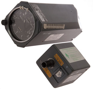
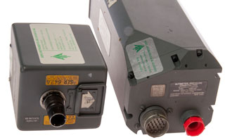
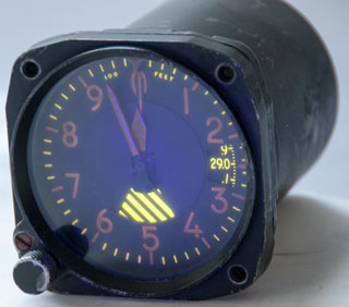
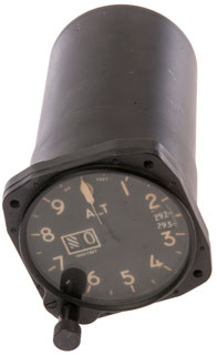
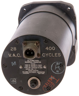
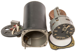
Altimeter that operates Zero to 80,000 feet but is only calibrated to 60,000 feet. I thought this was a servo type, but after opening it up it's not a servo type. I think the small electrical device is just a vibrator. These were added when jet aircraft, which fly much smoother than propeller airplanes came out. The idea is that mechanical instruments need a tap to break loose and large errors can accumulate if no one taps the instrument. So this built in vibrator does that job.
This uses an external 28 VAC 400 Hz electric power supply to operate the servo system based on the patents that Kollsman purchased.
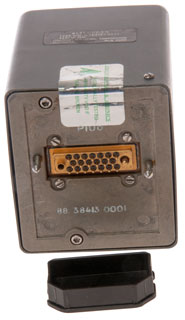
Markings on back (Fig 2).
What are the two components on the back plate Fig 5?
I expect the function is a vibrator, i.e. like tapping on the glass, but don't see how 29 VAC 400 Hz powers int.
28
V.A.C.
10SL-4
400
Cycles
M
Altimeter
Numerical Counter
Range
-1000 to =60,000 Ft. Calib.
-1000 to +80,000 Oper
Type No. B26542 10 001
Serial No. 787Patent Pending
Kollsman Instrument Corporation
Elmhurst New York
RC
K
31
[ ]
Tested
20
Photos
Fig 1
Fig 2
Fig 3 Comes out front.
Only the 400 Hz electrical device comes off back.
Fig 4
Fig 5 What are the two components?
---------------------------------------------------------------------
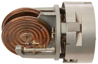
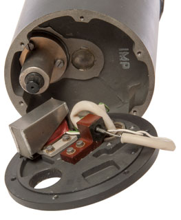
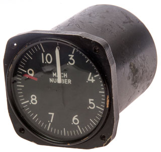
Kollsman Machmeter
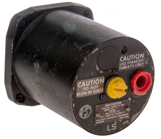
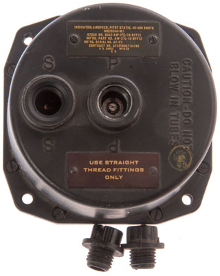
Mach number (Wiki) is the speed expressed as the actual speed divided by the local speed of sound (Wiki). The first order effect for the speed of sound is static air temperature. The first order effect for the speed of an aircraft relates to both the static and Pitot pressures, hence the two air inlet fittings on the back.
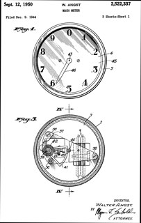
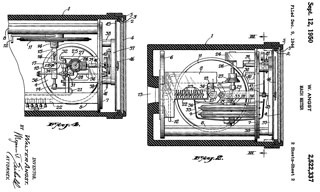
2522337 Mach meter (note Square D took over Kollsman so this patent is directly applicable.)
Markings
CAUTION
Use straight
threads only
CAUTION
Do not
blow in tubes
Machmeter
Type No. A31665 10 006
Serial No. 401
Range
M= 0.3 to 1.0
Alt= -1000 to +50,000 Ft
Kollsman Instrument Corporation
Elmhurst New York
LS
Photos
Fig 1
Fig 2
Fig 3
Fig 4
Fig 5
2522337 Mach meter, Angst Walter, Square D Co (Schneider Electric USA Inc), Filed: 1944-12-09, Pub: 1950-09-12 - reads 0 to 1, where at Mach 1 the plane self destructs (which is what they believed in 1944).
Airspeed Indicator
MS28046-W1 Airspeed Indicator
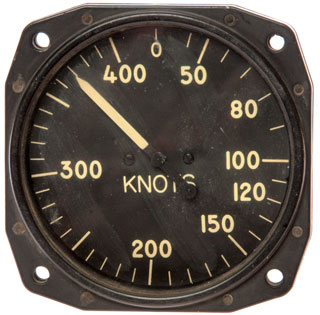
I think this is the airspeed indicator used on the AD (aka A-1) Skyraider. In that application it is located directly below the Mk 20 mod 4 Gun-Bomb-Rocket sight. The speed and altitude are key parameters that need to be controlled as part of using the sight.
Note that the indicated air speed (based on Pitot and static pressures) corresponds to how a wing generates lift. So the stall speed for the wind depends on indicated air speed, rather than true air speed.
See: YouTube:How To Design A Plane To Fly At 100,000 Feet?, 17:27, 14Feb2023 -
Photos
Fig 1
Fig 2
Generic Airspeed Indicator
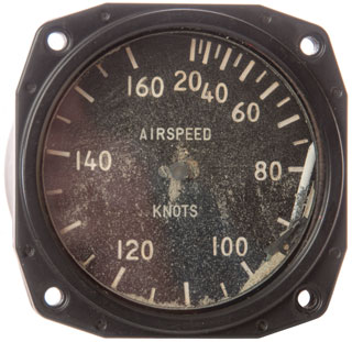
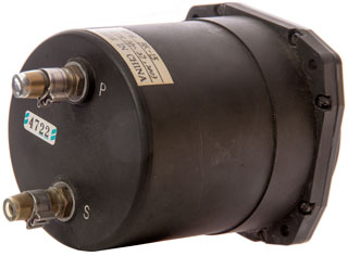
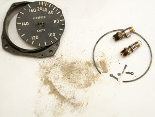
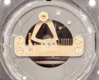
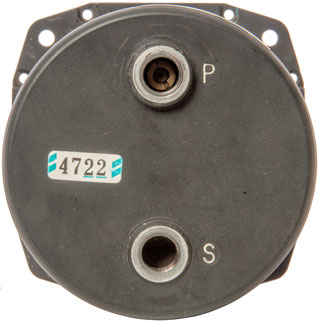
This was on eBay and something had happened to make it non operational. The needle is off it's shaft and there's what appears to be fine sand inside. It seems to have a single aneroid element and a bunch of screws, like
Photos
Electronic Altimeter
I used the word "Electronic" because there are a number of different methods of finding height that depend on electronics as opposed to barometric pressure. Most of them are not radar.
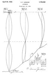
1756462 Altimeter, Jenkins Charles Francis, 1930-04-29, - At one wavelength above ground bright lamp, lamp dims as distance decreases.- cited by 12 patents
2529510 Radio system for measuring distance by phase comparison, Theodore M Manley, 1950-11-14, - for horizontal distance
2537574 Distance finder with automatic range tracking, Murray G Crosby, RCA, 1951-01-09, - uses audio phase shifter to get distance
2540076 Radio cycle summation measuring apparatus, Oscar H Dicke, App: 1944-09-28, W.W.II, Pub: 1951-02-06, - Bearing & Distance to RADAR reflector or aircraft (see Radiosonde)
2640190 System for measuring the thickness of opaque objects, Rines Robert Harvey, App: 1945-09-04, W.W.II, Pub: 1953-05-26, -
2931300 Radiant-energy projectile detonating system, Lord William Burton Housley, Tomlin George Maurice, Turner Henry Cobden, Secretary of the Navy, App: 1947-08-08, TOP SECRET, Pub: 1960-04-05, - see China Lake Patents
2977590 Method of testing a proximity fuze, Robert C Lovick, 1961-03-28, - see China Lake Patents
3113309 Method and apparatus for measuring altitude, John A Kuecken, Avco, - for landing, counts wavelengths to runway
3189899 Continuous wave radar systems, Arthur B Slater, Raytheon, 1965-06-15, - FMCW Radar (Wiki)
3191171 Radar height sensor and low altitude altimeter, Richard D Zuefeldt, David D Zak, Teledyne Ryan Aeronautical, 1965-06-22, - Teledyne Ryan also made Doppler Nav systems.
3216009 Measurement or control of the altitude of aircraft, Thomason Roy, Ripper Robots, 1965-11-02, - for aircraft landing
DE1221314 Arrangement for controlling the altitude of an aircraft, Thomason Roy, Ripper Robots, 1966-07-21, - for aircraft landing
20060158370 Distance measuring device, Shigemi Kurashima, Masahiro Yanagi, Takuya Uchiyama, Takashi Arita, Fujitsu, 2009-04-28, - UWB (Wiki)
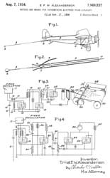
1969537 Method and means for determining altitude from aircraft, Ernst F W Alexanderson (Wiki), GE, 1934-08-07, - trailing wire antenna from spool to allow low frequency operation
Cited by:
2465723 Radio wave altimeter, Heller Douglas Max, GE, App: 1943-05-06, TOP SECRET, Pub: 1949-03-29, - blind-landing devices
2475020 Method for augmenting small phase differences, Gabrilovitch Leonide, App: 1943-11-23, W.W.II, Pub: 1949-07-05, -
2513530 Impedance measuring device utilizing oscillatory electric circuits, Stratton Andrew, 1950-07-04, -
2530905 Aircraft altimeter, particularly applicable to low altitudes, Ortusi Antoine Jean, Ponte Maurice, CSF, 1950-11-21, - waveguide, motor, CRT,
2540076 Radio cycle summation measuring apparatus, Oscar H Dicke, 1951-02-06, - See Radiosonde,
2665420 Radiant energy system for distance measuring, Alfred C Winterhalter, Sunoco, 1954-01-05, - "In brief, the system involves the generation of a high frequency with a, plurality of divisions of this frequency by frequency dividers to produce subharmonics of the generated frequency, the lowermost of which is caused to modulate a radio transmitter or a light source to send the modulated radio or light beam to a distant receiver. This bean is, in effect, reflected by the receiving apparatus, either by actual reflection in the case of the light beam or through retransmission in the case of a radio wave. The Signal thus reflected is received at the transmitting station and by frequency mulltiplication is transformed back to the original generated frequency and harmonic frequencies corresponding to those produced in the transmitter. The corresponding frequencies are then compared in phase so that a series of measuring devices measure the phase differences at all of the various frequencies." Maybe used to locate oil drilling platforms at sea?
2931300 Radiant-energy projectile detonating system, See China Lake Patents: Proximity Fuze
3216009 Measurement or control of the altitude of aircraft, Thomason Roy
3273112 Tuned seismic wave communication system, Leland S Hobson, 1966-09-13, -
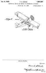
1987587 Electrical device and method of determining distances, Frederick H Drake, RCA, 1935-01-08, 342/120; 324/326; 342/127; 324/330; 367/99 -
Example1: 50' (15 meters) wingspan = half wavelength, full wavelength= 30 meters, so Freq = 10 Mhz (30 meters). When plane 1/2 wavelength (15 m, 50') above ground there's a maximum.
Example 2: Zeppelin, 600' (183m) half wave antenna, full wave= 1200', 365' or frequency of 820 kHz. First maxima at 600' above ground.
Patents that call this one:
Publication number Priority date Publication date Assignee TitleUS2465723A * 1942-05-06 1949-03-29 Gen Electric Co Ltd Radio wave altimeterUS2533769A * 1946-10-22 1950-12-12 Radio Electr Soc Fr Radio altimeterUS2540076A * 1944-09-28 1951-02-06 Oscar H Dicke Radio cycle summation measuring apparatusUS2923002A * 1957-01-14 1960-01-26 Douglas P Pielou Attitude indicatorUS2931300A * 1940-06-11 1960-04-05 Lord William Burton Housley Radiant-energy projectile detonating systemUS3071766A * 1958-08-27 1963-01-01 United Aircraft Corp Radar altitude controlUS3153236A * 1943-06-23 1964-10-13 Rines Robert Harvey System and method for detection
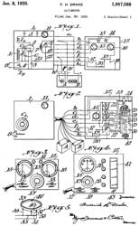
1987588 Altimeter, Frederick H Drake, RCA, 1935-01-08, 342/120; 367/107 -depends on reinforcement and cancellation as the wavelength of the Tx signal mixes with itself.
1991892 Height indicator, Reginald A Fessenden (Wiki), 1935-02-19, -
2011392 Airplane altitude indicating system, Jetson O Bentley, GE, 1935-08-13, - sawtooth frequency so probably FMCW - cited by 37 patents
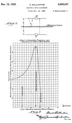
2020347 Electric wave altimeter, Ballantine Stuart (Wiki), RCA, App: 1928-12-15, (W.W.I SECRET) Pub: 1935-11-12, 342/120; 367/99 - max antenna impedance at 2.5x natural wavelength. shows bi-plane
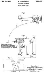
2022517 Radio Echo Altimeter, F.G. Patterson, GE, 1935-11-26, - The antenna impedance varies with height above ground causing a cyclic variation in the amplitude of oscillation. The illustration is of a single prop cloth high wing plane.
This patent is cited by 3166015 Radio frequency proximity fuze by Tuve. The single tube circuit is very straight foreword
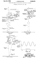
2045072 Method and means for measuring altitude of aircraft, Espenschied Lloyd, AT&T, 1936-06-23, -
30 MHz center with motor driving the tank capacitor so the frequency is FM modulated. Frequency shift 2 MHz at 100 Hz rate. So FM-CW Doppler (Wiki). Uses vibrating reed frequency meter as output indicator.
Mentioned in the NYT: How 5G Clashed With an Aviation Device Invented in the 1920s -
RTCA Report: Assessment of C-Band Mobile Telecommunications Interference Impact on Low Range Radar Altimeter Operations -
5G Americas Report: Mid-Band Spectrum & the Coexistence with Radio Altimeters -
FAA SAIB AIR-21-18: Risk of Potential Adverse Effects on Radio Altimeters -
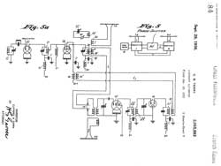
2055883 Aircraft altimeter, Clifford B Terry, RCA, 1936-09-29, 342/120; 73/384 -
The only citations relate to the problems of aneroid type altimeters, cited by 66 other patents, so maybe the father of radio altimeters?
In one embodiment this looks like a radar, but in another the frequency of the transmitter is determined by the elevation (Freq = 4 * Height/C, calibrated in feet instead of Hz).
In all cases separate Tx and Rx antennas.
2280725 Self-balancing capacity altimeter, Jr Francis H Shepard, RCA, 1942-04-21, - capacity bridge, for landing only
2417032 Electric altimeter, Wolff Irving, Jarrett L Hathaway, RCA, App: 1939-02-28, TOP SECRET, Pub: 1947-03-04, - "It is therefore one of the objects of this invention to disclose means whereby a frequency type altimeter for measuring higher altitudes may be combined with a capacity type altimeter for measuring lower altitudes may be combined with a capacity type altimeter for measuring lower altitudes. It is a further object to provide means for indicating altitude by a cathode ray tube which is combined with means for biasing the trace to indicate the lower altitudes. By the term "higher altitudes,' distances of the order of from 100 feet and upward is meant; the term 'lower altitudes' referring to distance determinations from approximately 200 feet to zero."
Cites
2011392
2228367
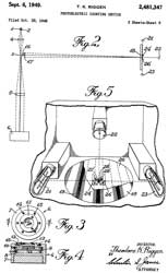
2481347 Photoelectric counting device, Theodore K Riggen, Bendix Aviation, 1949-09-06, - "...for counting light fringes traversing the field of view of an interferometric type of barometric altimeter suoh as set forth in Patent to Hurley:
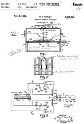
2410502 Aircraft control apparatus, Roy T Hurley, Bendix Aviation, App: 1940-04-06, TOP SECRET, Pub: 1946-11-05, - very sensitive altimeter to replace gyro auto-pilot systems for altitude control.
APN-1
The APN-1 (Wiki: FM-CW, Radar Altimeter) an early radio altimeter (Wiki).
Manual: AN-08-10-265, Approved 4 July 1944 (Revised 4 Jan 1945) Restricted (For Official Use Only) For: U.S. Navy, U.S. Army, British
Major Components: RT-7 Radio Transmitter-Receiver, ID-14 Altitude Indicator, SA-1 Altitude Limit Switch, AT-4 Antenna (one for Tx, one for Rx), MT-14 Mounting Base
Power: 28 VDC
Max Range: 4,000'
Bell Labs Record, Vol 26, Jan 1948 - Dec 1948, 12 issues, Jan 1948 Crystal lattice filters, Radio Altimeter (pg 18)
1517549 Railway signal system, Espenschied Lloyd, App: 1919-11-21, 246/63R; 361/1; 340/538.14 - to measure the distance along tract to a short (two wheels + axle).Links to other web pages:
2045071 Altimeter for aircraft, Espenschied Lloyd, AT&T, App: 1930-04-29, Pub: 1936-06-23 342/122; 342/462 - a motor applies +/-5% FM modulation to a 30 MHz carrier.
2045072 Method and means for measuring altitude of aircraft, Espenschied Lloyd, AT&T, App: 1930-04-29, Pub: 1936-06-23, 342/122 -
The Past In The Present - Tag: RT-7 / APN-1 Radar Altimeter -
YouTube:INFOAGE MUSEUM Military Electronics - APN-1 Radar Altimeter - up to 4,000 feet, controlled autopilot to maintain desired height for firing torpedoes, Tx antenna on one wing, Rx antenna on other wing, FM-CW? The signal does not beam down, the half-wave dipole antenna radiates in all directions. The system will report the closest target. APN-1 wartime radar altimeter demonstration - 420 - 460 MHz, 0.1 Watt, FM-CW, - The range switching looks like the RCA patent 2055883 above.
YouTube:
VmarsManuals: T.O. 12P5-2APN2-2: APN-2 & APN-2Y & APN-2B Maint. Manual -
SCR-718 Radar Altimeter
See Ref 8.
One of the major errors associated with the Norden Bombsight was in the height above ground (aka: absolute altitude). A Radar Altimeter gives a much more accurate answer than a barometric altitude.
This is a classic pulse type radar, unlike the FM based APN-1 above. Range 50' to 40,000' +/-50'.
This is an upgraded SCR-518 with a max range of 20,000'.
Frequency 440 MHz.
BC-788 Receiver and Transmitter; I-152 CRT Indicator; AT-4/ARN-1
NACA Technical Note 3186 Evaluation of the accuracy of an aircraft radio altimeter for use in a method of airspeed calibration, May 1954 (AD0030598.pdf), 19 pages. "The advent of aircraft that attain their maximum performance at high altitudes and the irregularities common to many types of airspeed installations at transonic speeds have combined to render inadequate for such aircraft the methods of airspeed calibration described in reference 1." This is because air density goes down as altitude increases, so jets go faster at higher altitudes. To get good results with a radar altimeter the testing needs to be done over a large body of water not only to get a good return but also since the reading will be the altitude above sea level.
HyperWar\USN: Navigation sets - SCR-518' SCR-718; ARN-1; SCR-640; SCR-620, PPN-1 Eureka; APN-2 Rebecca; APN-4 LORAN;
Doppler Navigation RADAR (Wiki, AN/APN-81)
As far as I can remember these systems worked at 13.3 GHz.
Radar altimeter for use in Saturn spacecraft, 1964 (pdf) - Ryan Model 520, 1606 MHz pulse, time of flight (Wiki)
Ryan in San Diego made Doppler Navigation systems that had a number of downward beams. This system only worked on aircraft that never did fly inverted such as bombers and helicopters.
Doppler Navigation: APN-79, APN-97, APN-130, APN-182, APN-193, APN-211, APN-213, APN-217, APN-218, APN-220, APN-231, APN-233 - all on aircraft that do NOT do barrel rolls, i.e. the bottom always points to the ground (not fighter aircraft).
2869117 Course and speed indicating system, France B Berger, William J Tull, General Precision Laboratory, 1959-01-13, - Doppler based
2908902 World-wide navigational system, John W Gray, Everett B Hales, Jr Ivan A Greenwood, General Precision Laboratory, 1959-10-13, - Doppler Navigation system for aircraft that always have their belly pointing at the Earth. Will not work with fighters.
Ryan Aeronautical (Wiki-
They made the Firebird AAM-A-1 air-to-air missile (Wiki, YouTube, 14:04) that used 13.5 GHz FM CW for terminal guidance, but required manual mid course guidance (I suspect that was a problem). Construction using terminal boards, not cord wood.
The Model 147 Lightening Bug (Wiki) was a reconnaissance RPV, derived from the Firebee jet powered target drone (Wiki).
3131390 Doppler-inertial ground velocity indicator, Marion A Condie, Leland S Reel, Ryan Aeronautical, 1964-04-28, - "The primary object of this invention is to provide a ground velocity indicating system in which Doppler radar is coupled to an inertial system to utilize the long term accuracy of the Doppler radar with the short term accuracy of the inertial system, to achieve high instantaneous accuracy over a long period, yet in which the inertial System contains a stable platform having a single gyro scope with only two axes of freedom."
3150367 Non-quantized cw-fm radar ranging system, Robert L Harrington, Ryan Aeronautical, 1964-09-22, - adds noise to FM-CW modulation
3184736 Attitude sensing by amplitude comparison of multiple radar beams, Charles J Badewitz, Ryan Aeronautical, 1965-05-18, - not Doppler, but compatible in the same system
3191171 Radar height sensor and low altitude altimeter, Richard D Zuefeldt, David D Zak, Ryan Aeronautical Co, 1965-06-22 -
3337867 Terrain slope or pitch and roll computer, Charles J Badewitz, Ryan Aeronautical Co, 1967-08-22, - adds vertical reference (gyro)
3344419 Wide angle measurement of terrain reflectivity, Thomas J Lund, Ryan Aeronautical Co, 1967-09-26, - probably to support Doppler Nav
3362024 Verticality, altitude and velocity sensing radar, Charles J Badewitz, Ryan Aeronautical Co, 1968-01-02, - much of Doppler Nav
3363253 Multi-beam resonant planar slot array antenna, Adam E Ratkevich, Ronald L Naylor, Ryan Aeronautical Co, 1968-01-09, - for Doppler Nav RADAR.
3430239 Doppler inertial system with accurate vertical reference, Heinz Buell, John M Fiore, Louis S Marino, Jack Rubin, General Precision Systems, 1969-02-25, -
3472471 Landing site selection radar, Charles J Badewitz, Ryan Aeronautical Co, 1969-10-14, - for use on Apollo Lunar Module (Wiki), was it used?
APS-13 Airborne Tail Warning RADAR (Wiki: Tail Warning Radar, Monica)
This was essentially an altimeter, i.e. it sounded an alarm if anything got within a certain distance of its antenna.
See Ref 7. As far as I can remember reading these turned out to be beacons that would lead an enemy right to the "protected" airplane.
The Fat Man bomb had four of the APS-13 altimeters and four pressure sensitive switches.
One application was on the Little Boy and Fat Man atomic bombs dropped on Japan so that they triggered at 18,000' altitude.
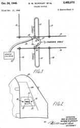
2452073 Folded dipole, Schivley George William, Paul W Springer, App: 1944-11-17, Pub: 1948-10-26, -
Has minimal sensitivity forward, left or right - main lobe to back and down.
Another application was on the P-47N Thunderbolt (Wiki).
Pressure Sensitive Switch
Four of these were part of the Fat Man bomb.
3358605 Pressure Sensitive Switch, Alan N Ayers, App: 1946-01-04, Top Secret; Pub: 1967-12-19. - must be sensitive and must not actuate under strong vibration.
Rate of Climb
Rate of Climb (Wiki) is more complex that what you might think. One way to measure Rate of Climb is the Variometer (Wiki) which is based on pressure altitude. That's to say it's an altimeter with a leak and so shows changes in air pressure rather than changes in altitude above ground.
The problem with the pressure altitude rate (leak) type of Variometer is that the pin hole or capillary tube may get plugged up. The response time is slower than desired.
The Electric Variometer System, A. Gene Moore, 1969 - Types of Rate of Climb instruments:
ClearNav Instruments (CNv) Variometer pneumatics – probes, tubing, restrictors, etc. -
- Leaky Capsule
- Vane Type
- Pellet Type
- Thermistor Type
- Total Energy Variometer AOPA: How it works: Total Energy Variometer: Measuring the ups and downs of soaring - "Rising air such as in thermals, however, supplies the kind of lift that can keep sailplanes aloft for hours. An uncompensated variometer shows a climb no matter the cause, so a pilot might mistake a self-induced “stick thermal” for a real thermal. Total energy systems solve this problem by compensating for the speed of the aircraft." -
NASA A Simple Total Energy Sensor, March 1976 (Total_Energy_Compensators.pdf) -
RC Groups: Variometer "total energy compensation"
Uncompensated Vario
The formulas for an uncompensated vario are:
Potential Energy = mass * gravity * height
Vario output = change in PE / change in time
An uncompensated vario only accounts for PE. As such, it only signals the change in height over the change in time ... a rate of climb indicator.
Compensated Vario (Total Energy Compensation)
The formulas for a compensated vario are:
Potential Energy = mass * gravity * height
Kinetic Energy = 0.5 * mass * velocity^2
Total Energy = Kinetic Energy + Potential Energy
Vario output = change in TE / change in time
The compensated vario accounts for the exchange of KE and PE. A glider is generally considered to have a lossless trade between KE and PE, which happens whenever airspeed changes and exchanges for altitude. A gentle pull-up trades airspeed for a gain in altitude with no net change in total energy, like a roller coaster. A gentle push-over trades altitude for airspeed with no net change in total energy.
Interestingly, a precision device called a total energy nozzle (TEK nozzle) can be installed that mechanically trades pressures to give the same equations. There are two small holes in the backside of a tube of a specific size. The suction area behind the tube helps provide the compensation for KE as static pressure (PE) changes. Using a TEK nozzle allows using only one pressure sensor instead of separate altitude and airspeed inputs!
Netto Variometer
The glider's polar only matters if you're talking about a netto variometer. In pseduo-math, the formula is:
Netto Vario output = compensated vario output - sinkrate due to drag
The sinkrate due to drag varies with airspeed, also known as the sink polar (a.k.a. the power required curve). It is certainly true that a Gentle Lady will have a different sink polar than say a 4m Cross Country ship. However, the sink polar is commonly assumed to be a polynomial, simply scaled for different vehicles. However, a compensated vario does not care about the polar, only the netto equation.
Practically, the netto vario signals only the airmass motion. Your glider might be losing energy, but in an airmass that is rising (flying too fast in a thermal). Subtle difference. I prefer a netto signal personally to better visualize the air motion, but the pure compensated vario is a better indication to the pilot if the aircraft is losing or gaining total energy.
Eagle Tree Compensation?
Not using the Eagle Tree vario myself, I will say that the first important piece for tuning a variometer is to make sure it signals zero when sitting still on the table. The two hobby varios I have used have a bias adjustment to set the zero. I hope the Eagle Tree has something similar.
Also not using the Eagle Tree, I can only guess that the compensation percentage may dilute one of the terms. It could be by only taking a part of the KE term (which is V^2), it is possible to approximate the sink polar's effect. If this is the case , then they are incorrectly using the term "compensation" when they should be describing the effect as "tuning for netto." You may talk with their tech department enough to get a programmer on the line...
Dan Edwards
Raven Electronics - for models & sailplanes
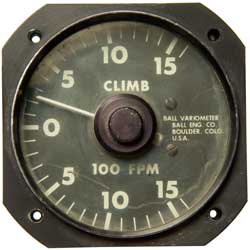
Ball Model 500
Range zero to plus or minus 15 hundred feet per minute.
There is a provision for a 9 Volt battery so this may be a capacitive type rather than a pressure altitude leak type Variomenter.
There is a three position switch marked "A" (off?) and "V" as well as a knob marked "VOL". Let me know what these do.
Photos
Patents cited in 4086810 & other prior art rate of climb instruments.
Fig 1
Fig 2
Fig 3
1664417 Combined statoscope and rate-of-climb indicator, Franklin L Hunt, Atherton H Mears, 1928-04-03, -
1929091 Rate of climb instruments, Charles H Colvin, Pioneer Instrument Co, 1933-10-03, -
1935736 Indicating instrument, Charles H Colvin, Urfer Adolf, Pioneer Instrument Co, 1933-11-21, -
2127836 Rate of climb instrument, Urfer Adolf, Pioneer Instrument Co, 1938-08-23, -
2142338 Rate of climb indicator, Alfred E Sidwell, Bendix Aviation, 1939-01-03, -
2159703 Rate of climb indicator, Paul W Koch, Bendix Aviation,1939-05-23, -
2445335 Altitude and rate of change measuring device and control for aircraft, George A Philbrick, Allan R Catheron, Schneider Electric Systems (Foxboro), App: 1941-05-03, W.W.II, Pub: 1948-07-20, -
2531492 Rate of change indicator, Angst Walter, Jr John H Andresen, Schneider Electric (Square D), 1950-11-28, -
2656721 Pressure responsive photoelectric indicating, meansuring, and control device, Frederick C Melchior, 1953-10-27, -
2718783 Rate of change of pressure and pressure measuring indicating instrument, Harry G Anastasia, Bendix Aviation, 1955-09-27 -
2775122 Vertical velocity computer, Robert E Smith, John M Wuerth, North American Aviation, 1956-12-25, - combines altitude rate & accelerometer
2775123 Rate of climb indicator, Salle Rene, Sevin Paul Etienne, Mottais Jean Olivier, NATIONALE DE CONSTRUCTIONS AERONAUTIQUES, 1956-12-25, -
2775124 Angle of attack computer, Frederick H Gardner, James C Elms, Rosenstock David, North American Aviation, 1956-12-25, -
2930035 Terrain clearance control apparatus, John L Altekruse, Goodyear Aircraft, 1960-03-22, - RADAR & barometric - cruise missile?
2931221 Altitude and altitude rate of change meter, Stanley J Rusk, 1960-04-05, -
2934267 Vertical speed computer and altitude control, Walter H WirklerWilliam G AndersonTheodore R Willis, Collins Radio, 1960-04-26, -
2964949 Induction velocity meter, Doyle E Wilcox, North American Aviation, 1960-12-20, - precision acceleration for inertial navigation (also for rate of climb).
3055214 Aircraft instruments, Robert C Mclane, Honeywell, 1962-09-25, - gyro pitch rate + altimeter
3098381 Vertical speed indicator, David S Little, Washingon Port, Edward W Pike, 1963-07-23, -
3196691 Wide band sensing apparatus, Alfonso S Escobosa, North American Aviation, 1965-07-27, - wide band = fast response time, op amps
3242736 Altimeter system, Winter Herbert, Theodore L Roess, Bell Aerospace, 1966-03-29, - "...a radar altimeter or a pressure-sensing de vice may not provide sufficiently accurate steady state altitude measurement as a function of time and place." altitude rate & accelerometer
3276255 System for development of complemented vertical speed in aircraft, Edwin R Hattendorf, Collins Radio, 1966-10-04, - accelerometer + altitude rate
3374671 Vertical rate sensor, Sidney B Williams, Edward T Rigney, Trans Sonics, 1968-03-26, - capacitance
3451265 Fast response apparatus for measuring rate of change of pressure, Richard H Ball, 1969-06-24, -
3572115 Altitude rate transducer and computing circuit, Robert Feuer, Conrac Avionic Systems, 1971-03-23, - delta static pressure
3683690 Variable time constant altitude rate device, John H Andresen Jr, International Dynamics Corp, 1972-08-15, - delta static pressure
3703828 Capacitance variometer, Edwin R Bullard Jr, Wesley L Joosten, Globe Universal Sciences, 1972-11-28, - capacitance
3726138 Digital displacement and displacement rate generator, H Kosakowski, C Smialowicz, Bendix, 1973-04-10, - delta static pressure
3789661 Aircraft glide angle and rate of change of total energy indication means, F Melsheimer, 1974-02-05, - time rate of change of the kinetic and potential energy characteristic of the aircraft in flight;
3885430 Vertical speed command instrument, Leonard M Greene, Safe Flight Instrument Co, 1975-05-27, - altitude rate + pendulum (acceleration)
4086810 Aircraft instrument, Richard Harding Ball, 1978-05-02, - "The vertical motion of the air outside of the aircraft (termed NETTO) (Google Groups) may be derived by subtracting the polar sink of the aircraft from the generated rate of climb information. "
4539843 Altimeter and vertical speed indicator, Fred W. Wise, Aerologic, 1985-09-10, -
Miscellaneous
1980732 Compensating device in measuring apparatus, Paulin Josua Gabriel, 1934-11-13, - "...to eliminate measuring errors in sensitive apparatus, such as aneroid barometers, due to elastic inertia, or hysteresis in the movable system."
1983486 Measuring instrument, Paulin Josua Gabriel, 1934-12-04, - aneroid barometer that work by manual zeroing
2011774 Measuring instrument having automatic zeroizing mechanism, Paulin Josua Gabriel, 1935-08-20
2609685 Aircraft instrument, Jr John H Andresen, KOLLSMAN INSTR CORP, Filed: 1944-09-22, Pub: 1952-09-09 - air speed and indicating in response to the aircraft angle of attack.
3279250 High-low airspeed indicator, Hezel Herman, Heinrich E Barthel, Walter H Rath, KOLLSMAN INSTR CORP, 1966-10-18 - dual capsule dual pointers 0 to 800 knots
3104546 Safe flight airspeed mechanism, Hauptman Frederic, KOLLSMAN INSTR CORP, 1963-09-24 - "Coffin Corner"? (Wiki)
3279250 High-low airspeed indicator, Hezel Herman, Heinrich E Barthel, Walter H Rath,KOLLSMAN INSTR CORP , 1966-10-18 - 1 to 800 Knots for helicopters- dual capsule
2410632 Inflatable Suit, Russell S Colley, Carroll P Krupp, Donald H Shook, Goodrich Corp, Filed: 1943-08-03, Pub: 1946-11-05
2954562 Inflatable protective suit for high altitude flight, Carroll P Krupp, Goodrich Corp, Filed: 1953-10-20, Pub: 1960-10-04 - long before space flight, so probably for the U-2 (Wiki) - 60,000 feet or more is mentioned.
2966155 Omni-environment inflatable suit for high altitude flight, Carroll P Krupp, Goodrich Corp, Filed: 1954-07-26, Pub: 1960-12-27 - 65,000 feet mentioned
3286913 Rotary pump, Herbert W Kaatz, Tobacman Leo, RANDOLPH Manufacturing Co, 1966-11-22, - cites 1804604 Pump, Silent Glow Oil Burner Corp, 1931-05-12 which is a vane type pump which can produce a high vacuum (i.e. will self prime).
3379135 Torsional coupling, Herbert W Kaatz, Airborne Manufacturing Co, 1968-04-23, - used to couple a DC PM motor to a backup vacuum pump
3565558 Rotary pump with sliding vanes, Leo Tobacman, Airborne Manufacturing Co, 1971-02-23, - driven by a DC PM motor to provide backup vacuum. This is the type of air motor used in most air powered impact tools.
Sperry C14 Airspeed Indicator p/n: 1426-1Z-A1
RE19709 Indicating instrument, J.D. Peace Jr, Pioneer Inst Co., Sept 17, 1935 -
2137194 Indicating instrument, Philip F Weber, Bendix Aviation Corp, 1938-11-15 -
2140972 Means for illuminating dials of instruments, Gregory V Rylsky, Bendix Aviation Corp, 1938-12-20 - grain of wheat lamps screw in from front
2194624 Diaphragm pressure gauge having temperature compensating means, Jr George A Titterington, Bendix Aviation Corp, 1940-03-26 - uses bi-metal wire
2196932 Pressure responsive indicating instrument, Menzer Anton, Bendix Aviation Corp, 1940-04-09 - allows adjustment of offset and scale factor to match pre-printed dial face.
2215570 Sealing means for indicating instrument casings, Roy C Sylvander, Bendix Aviation Corp, 1940-09-24 - 0 to 20,000' altimeter
2259910 Sealing and illuminating means for indicating instruments, Gregory V Rylsky, Bendix Aviation Corp, 1941-10-21 -
2227368 Illuminating adapter for instruments, Gregory V Rylsky, Bendix Aviation Corp, 1940-12-31 -
Kollsman DC-8F
3104546 above
2706407 Airspeed Indicator,Norman F Hosford ,Bendix Aviation Corp , Filed: 1949-03-28, Pub: 1955-04-19 - dual capsule
3040168 see
Piper True Airspeed
284209 True airspeed indicator, Ronald L Kennedy, 1958-07-08 - manually set altitude and temperature
Calls:
2174608 Indicating instrument
2217564 Combined air-speed indicator and rate-of-climb indicator
2251498 Air speed indicator -
2318153 True airspeed indicator - air temp, altimeter & indicated airspeed all drive pots which combine to drive meter for true airspeed.- cited by 20 patents
2706407 Airspeed indicator(see Kollsman DC-8F above)
Related
Navigation
Sundials
Surveying
Weather
MD1 Star Tracker Navigation System
S5807 Preiscopic Sextant
Theodolites - use very high resolution glass disks to read to sub arc seconds.
Waltham (and other) Aircraft Clocks
Aircraft Pilot's Standby Magnetic Compass
Aircraft Cockpit UV Instrument Light
References
Ref 1. “History of [the] U.S. Army Topographic Laboratories (1920 to 1973)”. (AD0785549)
Chapter 6. R&D Programs mentions:Ref 2. History of the Altimeter
pdf g 81 W&T altimeters adopted 1943
pdf pg 83 Astrolabs
2600266 Pendulum retaining means, Rothweiler Charles, David White Company, 1947-03-06 - 60 deg pendulum Astrolabe (Google)
Ref 3. NACA: Report No. 127, Aeronautic Instruments, Section III, Aircraft Speed Instruments. F.L. Hund & H.O. Stearns, Bureau of Standards, 1923 (Google.pdf) -
Ref 4. NACA Report No. 13, Meteorology and Aeronautics, Blair, 1917 (Google.pdf) -
Ref 5. Evaluation of RYANAV Doppler Navigation System, 1962, 39 pgs, ADA030561.pdf - 13.3 GHz, not suitable for Army helicopters.
Ref 6. Survey of Self-Contained Navigation Systems, 1951, 51 pgs, declassified Oct 2017 - Doppler, Star Trackers (Kollsman Celonavigator), Inertial (MIT SPIRE, GM SIBS, NOrth American Aviation MX-1688B w/ Hughes IR star tracker), Magnetic (Consolidated Vultee), dead reckoning, RADAR PPI map matching (Goodyear Aircraft),
Ref 7. How the WWII Fighter Tail Warning Radar reduced losses by 80%, the AN/APS-13 Deep Dive Review, 8:54 -
Ref 8. The clever instrument WWII Bombers used to determine their altitude - The SCR-718 Radar Altimeter, 9:10 -
Links
Analog Weather - Instruments & some pdf manuals
PRC68, Alphanumeric Index of Web pages, Contact, Products for Sale
Page Created 28 April 2018
