Wire Antennas
© Brooke Clarke, N6GCE 2008 - 2026
|
|
as
received
|
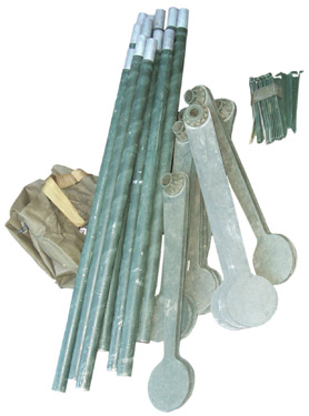
components
of
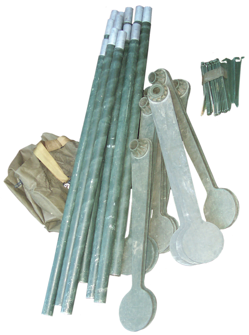
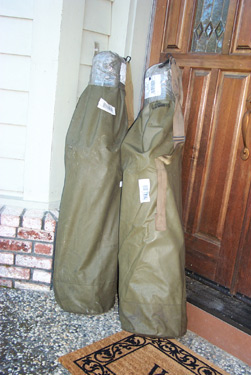
one bag
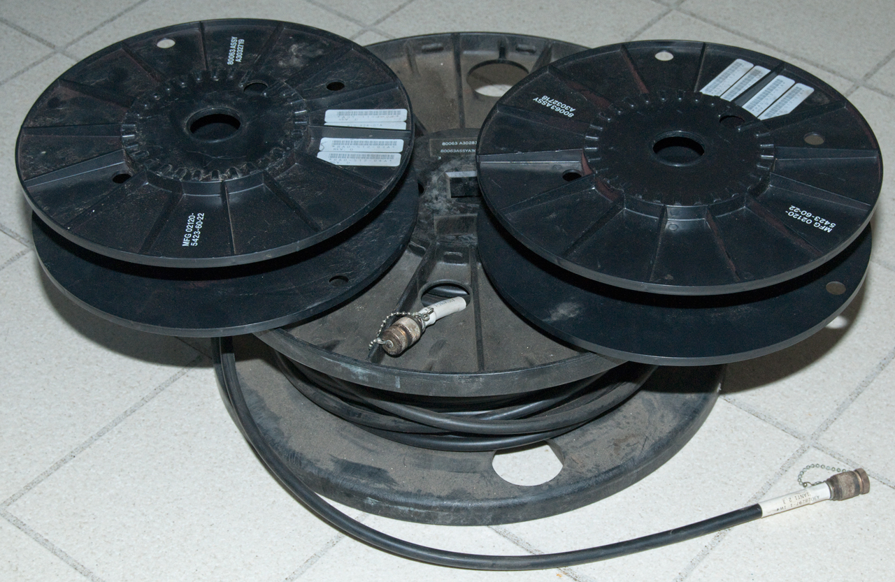
12 Al poles, 6 spreaders, 18 stakes
|
Background
Description of the Camouflage Screening Support
System
Mast Section Description
AB-1089 Does NOT Fit
How Used for Camouflage Screen
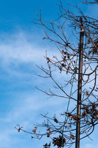
Antenna Mast
Spike Base, NEW, 1.5 and 1-5/8 OD GRC Ham
Manuals
Wire antenna Use
Parts Needed
Idea on Supporting BWD-180
Line Launchers
E-Z Hang Slingshot
CSV17 Tennis Ball Line Launcher
Kongsberg
M52
Patents
Handheld Throwers
Retriev-R-Trainer
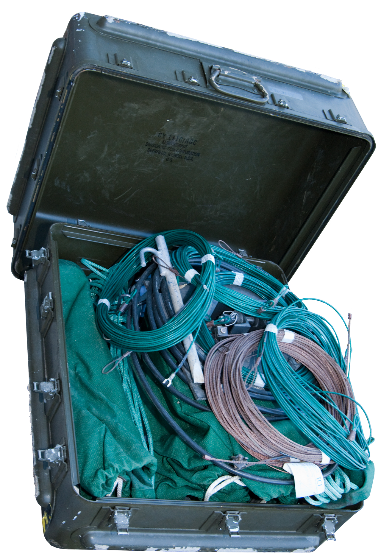
Targeteer (Can Cannon)
Type 89 Knee Mortar
Launched Grapnel Hook
Air Boss
PCP Tanks
TCI 651T
Photos
Description
Bill of Material
Installation
Spectrum Analyzer Plots
Operation
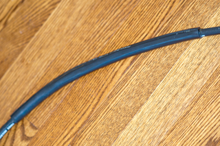
Coax Problem
Direct Burial + UV Resistant
Wire Antenna Patents
Other Wire Antennas
Links
Background
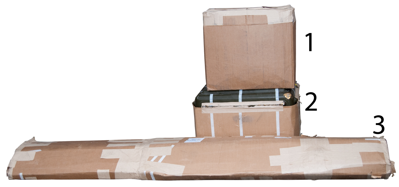
This page was started after I
received a couple of the Camouflage Netting Mast Kits. The
Intent is to use the aluminum mast sectiions to support a wire
antenna. There are military mast kits, like the GRA-4 or
GRA-12 that are much more expensive. Using these Camouflage
poles may be a lower cost alternative.
Description of the Camouflage Screening
Support System
There are a number of versions of
the system. Coloring comes in three flavors: Desert,
Woodland and Snow. Each of these has two sides to the
netting that are slightly different for the different seasons of
the year. Also there are radar scattering Type II, III and
IV as well as radar transparent screens. The radar
scattering screens are not on the surplus market but the radar
transparent type are available.
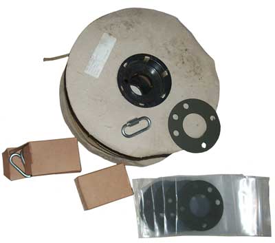
Each kit comes in it's own
bag. One of mine is marked:
1080-01-108-1173 (NSN for Woodland/Desert Support system, not just
the bag)
Camouflage Screening
Support System
Woodland/Desert
97403/4M703
DAAJ00-88-C-B513
Lot # 054
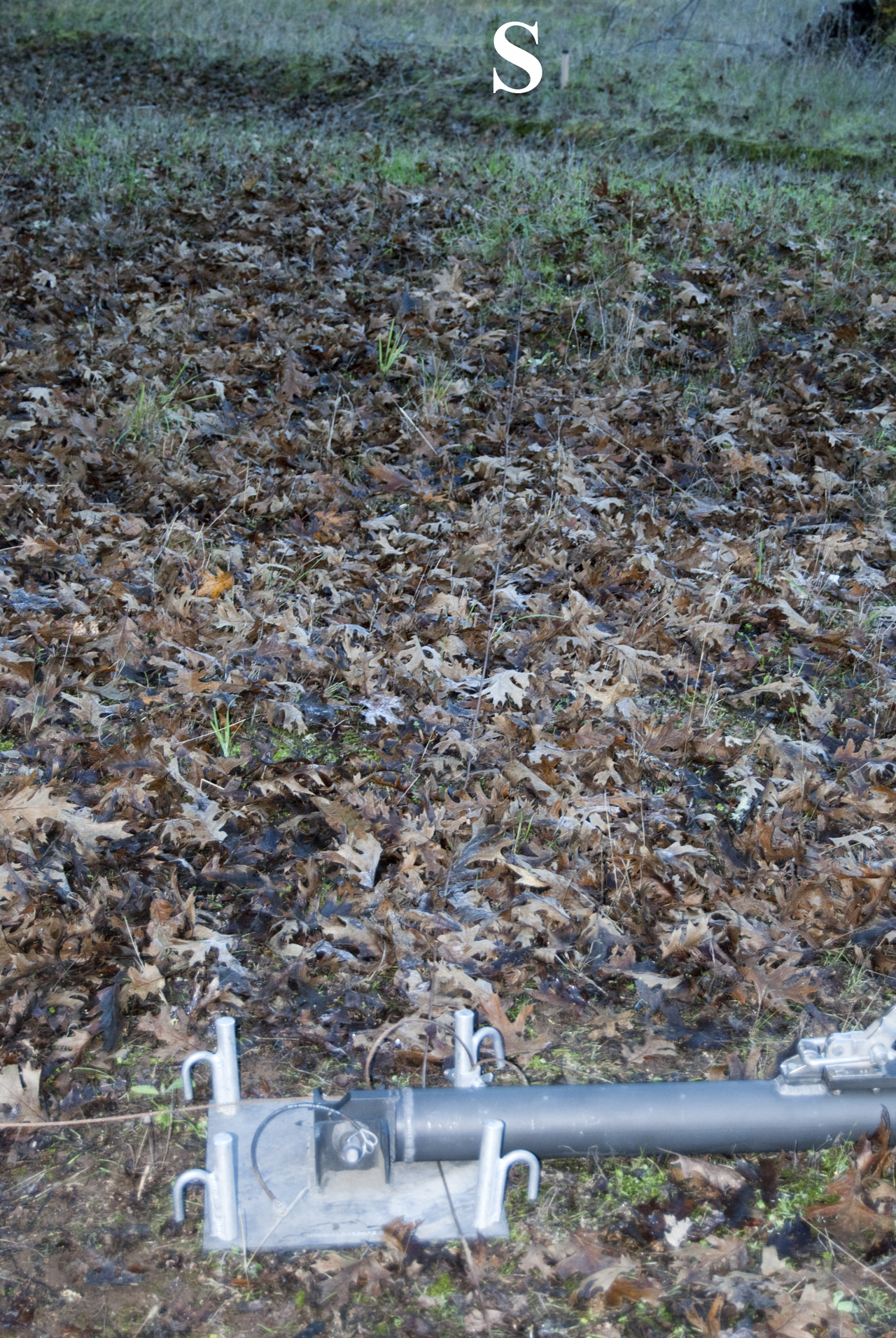
Contents of the bag:
12 aluminum Poles 44.5" long (excluding the connector)
6 Spreaders
18 Stakes
Mast Section Description
Each mast section is a tube just
under 4 feet in overall length. It's made of two tubes that
are swaged toghther. The outer tube is 1 25/32" O.D. (
1.785") and is 1 9/16" I.D. (1.5625).
The smaller tube is about 5 7/8" long and is inside the main tube
for a little over 1 1/2". It's O.D. is the same as the I.D.
of the main tube and it's I.D. is 1.35". There are two swag
rings that lock these together.
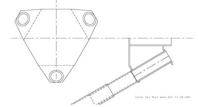
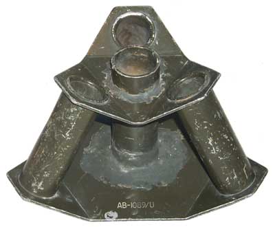
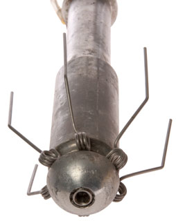
AB-1089 Does
NOT Fit
The AB-1089/U is a triangular
assembly that has three tubes that accept mast sections to be used
as the legs of a tripod and a center tube that accepts the
mast. The tripod leg tubes have an I.D. of 1.365" which is
also about the I.D. of the cammo netting mast small tube I.D.,
i.e. the cammo net mast will NOT fit the AB-1089.
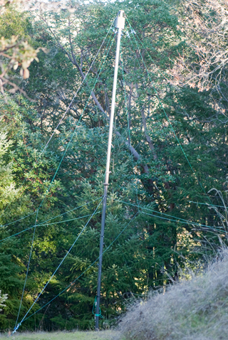
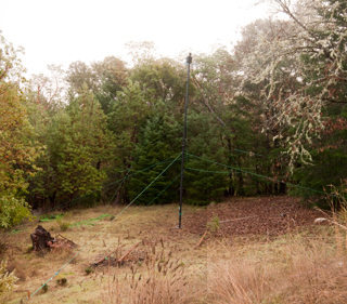
How Used for Camouflage Screen
Intended use is to combine one
spreader assembly (one adapter assembly and three pedals) with
various numbers of poles (1 to 4 typically) where the pedals
support the Camouflage Screen and the stakes are used to hold down
the screen. No guys are used in the system.
Antenna Mast Spike
Base, NEW, 1.5 and 1-5/8 OD GRC Ham
The above title is taken from the
eBay auction where this was being sold. The 1.5" OD
section of the base fits the mast base. It's similar to
the AB-154/U Spike Base (What is the O.D. of the AB-154?
let me know). Maybe they made
these by turning the AB-154 in a lathe?
Manuals
TM 5-1080-200-10-HR Lightweight
Camouflage Screen Systems
TM 5-1080-200-13&P Lightweight Camouflage Screen Systems and
Support Systems
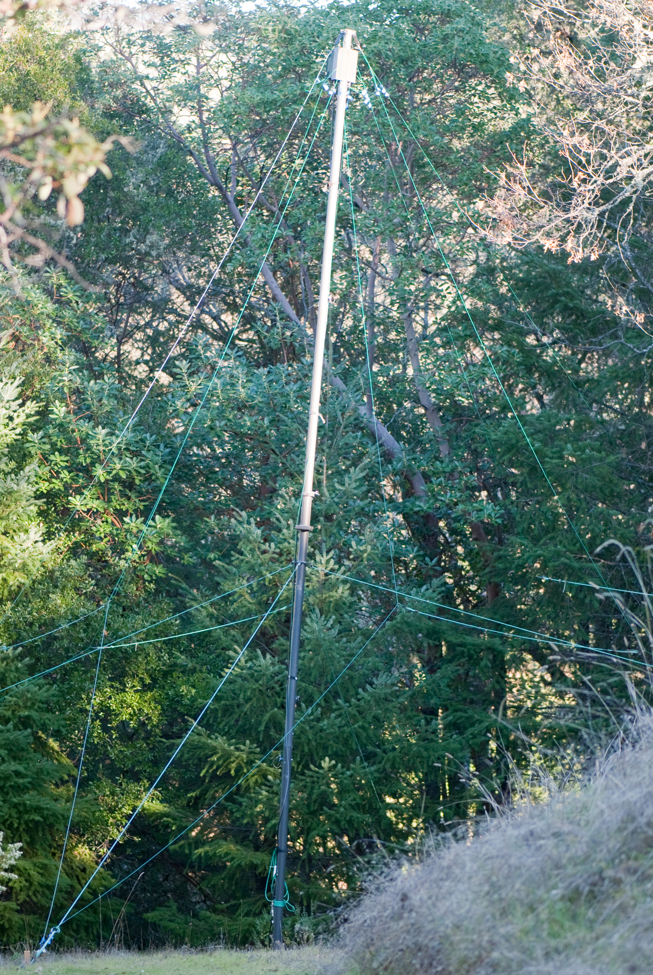
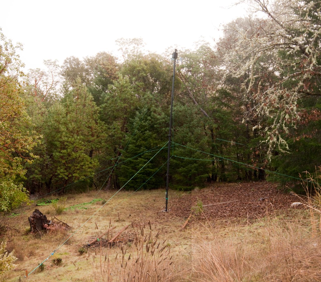
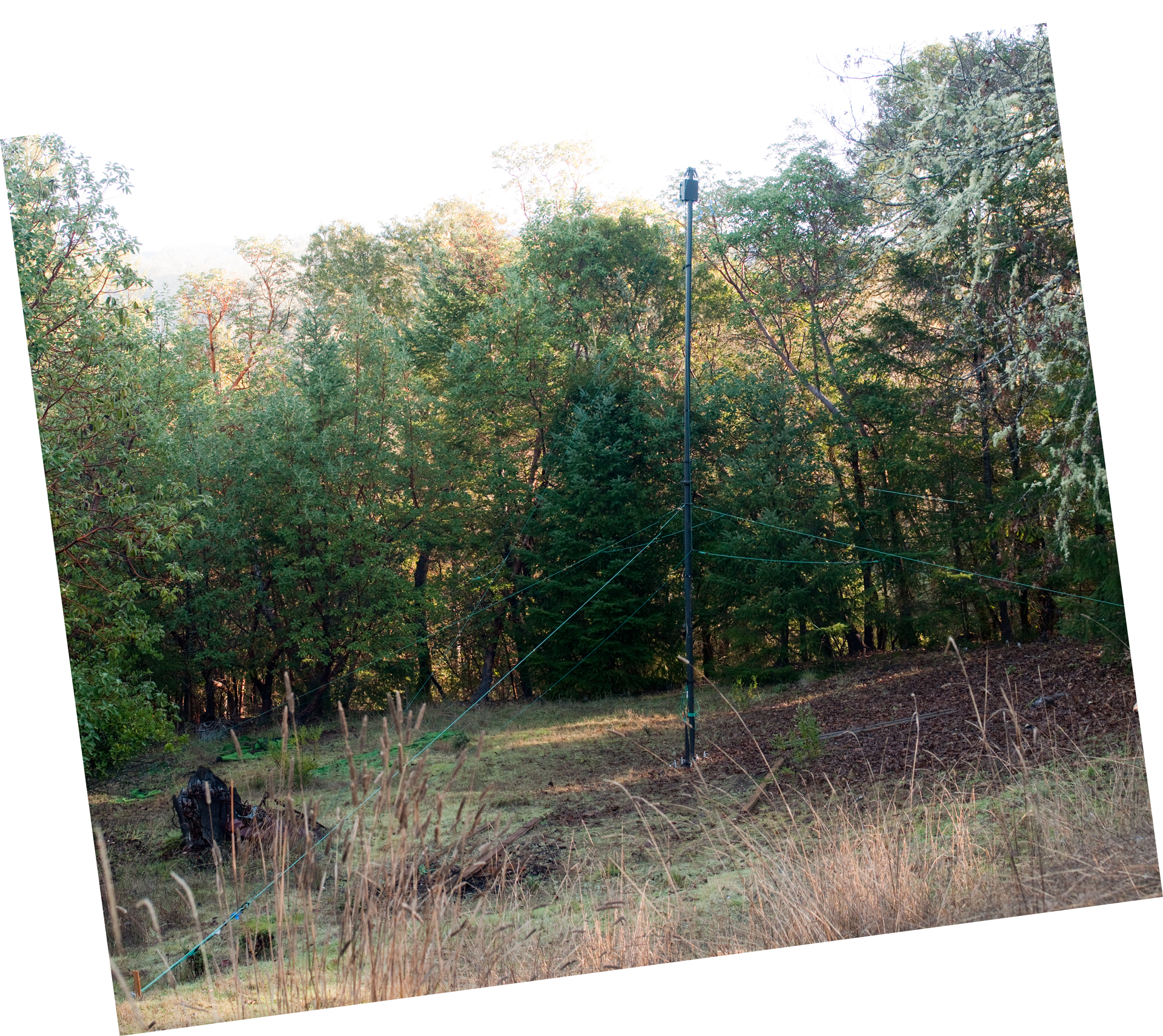
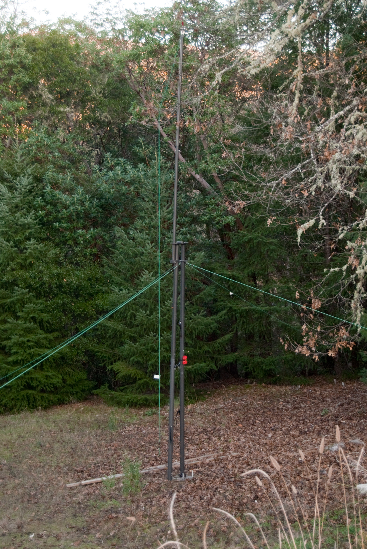
Wire Antenna Use
When used to support a wire antenna
the mast sections would be stacked to get (12 sections *
44.5"/section=) 534" (44.5 feet) if all 12 sections are in one
mast. Note that the poles need to support not only the
weight of one end of the wire antenna they also need to support
the vertical component of the guy tension and the vertical
component of the antenna tension. The latter value can be
quite high if you try to pull the wire very tight to minimize wire
sag. These vertical loads are why the telescoping type
masts are said to be used for "Light Weight" wire antennas
only.
Parts Needed
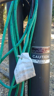
To use these poles for a wire antenna the following additional
parts are needed:
Guy Rings - 2, 3 or 4 rings depending on overall mast height
Quick-Links - between guy rope and Guy Rings
Guy Ropes - enough for all the guys - rule of thumb the distance
out from the base should be about 2/3 of the guy ring height or
more. With two or more guy rings on a mast it's common to
use only one stake for each azimuth, but it would be stronger to
use a separate stake for each guy rope.
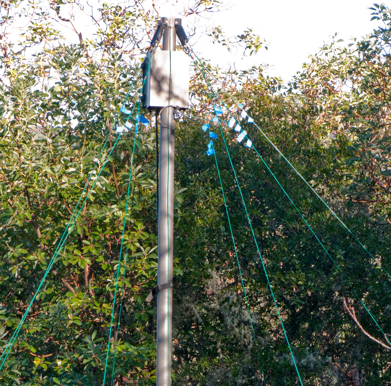
pulley and way to attach it to top of upper mast section.
The guy rope shown at left is from
The Mast Company is not
parachute cord, but rather appears to be the same material used
for guys on military mast systems.
Halyard & Pulley - to raise antenna after the mast is in
place. Note: It's much harder to erect a mast with the
weight of the antenna already attached, but can be done with light
weight antennas.
Base anchor - one for each mast - needed to keep mast from
punching into the ground. An option is to put something hard
below the mast.
Idea on Supporting BWD-180
This is a 185 foot long T2FD type
dipole with 3 foot separation between the wires. Unlike the
BWD-90 which can be supported by just the ends this one requires
additional support at the center. I was thinking that means
a center mast, but today realized that's not the case. For
example if pulleys are installed at each end and at the center
FDMK Mounting Kit the antenna can be pulled over a support line
using a second antenna line attached to one end of the
antenna. The support line may for example have one end high
up in a tree. Once the antenna has all three pulleys on the
support line, it's other end can be lifted using a second pulley
arrangement on one of the camouflage support masts.
This method can also be used to support the center of a dipole by
running the center up one of the guy lines of a mast. The
advantages of this are:
- The dipole center can be a few feet from the metal mast
instead of in contact with it.
- The coax feed line can have pulley supports every so often
so it's not completely carrying it's own weight.
- It's possible to adjust the position of the antenna, not
just it's elevation.
By combining the support line idea with multiple masts it should
be possible to fold the antenna rather than deploy it in a
straight line. It's not easy to come up with a 200 foot long
straight section of clear ground.
Line Launchers - Getting Wire Up Into
Trees
With the availability of the DJI quad copters, like the
Mavic mini 2,
the below attempts seem way out of date. The DJI can easily
go up many hundreds of feet with precision control and easily lift
a pilot line.
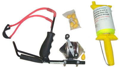
This is a stock
slingshot that has the fly casting reel added. It's shown
right side up. You put your hand up through the hole behind
the grip. That way the metal hoop (the foam pad should be
moved back to the top of the metal loop) is on top of your
arm. When you pull back the elastic the hoop keeps the grip
from rotating backwards.
There is some friction caused by the reel in playing out the mono
filament line. I've read that putting newspapers down in
front of the shooting position and playing out a couple hundred
feet of line may lower the resistance, but it's a lot of effort to
do that and keep from tangling the line.
I used this to get one end of a BWD-90 T2FD up about 90- feet into
a pine. But a couple of years later when the line broke
where the tree rubbed against it this slingshot was not able to
get the line over then now 120 foot tall tree.
2672857
Arm-supported slingshot,
Albert
H Gauthier, 1954-03-23, -
3901209
Wrist braced slingshot,
Robert
Woolsey,
Wallace
C Kerr,
L&R
Inc, IHO Holding, 1975-08-26, -
4606512
Bimodal fishing reel assembly,
Robert
R. Dennison, 1986-08-19, - one of the modes pulls the line
off the face of the reel, but the reel axle is still at right
angles to the rod, unlike the reel shown here were the reel axle
and parallel with the rod.
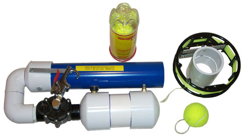
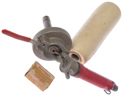
This is a
CSV17 tennis ball launcher based on the potato guns made from PVC
pipe fittings.
This set includes an assembled launcher with air pressure gauge
and safety valve. A special line reel to allow the line to play
out with minimal friction and tennis balls fitted with 90 # test
stainless steel loops and weighted for better throw. Not
shown, but included is a short PVC pipe and end fitting to ram the
tennis ball into the barrel.
A small
air comprerssor is on the
way and next spring this should put a line over the tall tree.
Golf Ball Launchers may be another way of launching a line.
Although I haven't seen one that included a provision for a
line. If you know of one please let
me know.
Another option may be to replace the compressed air
storage tank and valve with a chamber that would hold a
construction .22 blank cartridge.
Kongsberg M52
YouTube: Kongsberg M52: A
Line-Throwing Rifle (or Harpoon Gun), 8:38 -
Did not find a patent for this.
Patents
Line Launcher
General
203274
Line-throwing apparatus, Edmund S. Hunt, 1878-05-07, - gunpowder
fires a shot from tube
305873
Line-throwing gun, Jeremiah Williams, 1884-09-30, - harpoon gun
310852
Line throwing projectile, Philander B. Boys, 1885-01-13. - rocket
331792 Gun
and projectile for throwing life-lines, Simon Ingersoll,
1885-12-08, - specialized rifle
348848
Projectile for Throwing Life Lines, Simon Ingersoll, 1886-09-07, -
specialized rifle
797613
Line-throwing apparatus,
William
Schermuly, 1905-08-22, - mount for rocket and line
1418964
Line-throwing apparatus, Norman
George, B
S A Guns Ltd, 1922-06-06, - attachments to rifle
1575321
Line-throwing gun, Gregory
C Davison, Cecil
P Caulkins, American
Ordnance, 1926-03-02, - has the look and feel of an
antique field mortar
2069276
Life line projectile, Ryan
Michael J, Feb 2, 1937, 102/504 - line connects on parallel rod
to improve flight characteristics2111374 Line throwing
mechanism for pistols - See Sedgley patents
2388749
Cord holder for line throwing guns, Pierre
Alfred T La, Harrington
& Richardson Arms, App: 1944-12-19, W.W.II, Pub: 1945-11-13, -
can with specially wound cord - cited
by 7
2420347
Line throwing gun kit, Joseph
W Baldwin, Harrington
& Richardson Arms, App: 1944-12-19, W.W.II, Pub:
1947-05-13, - rifle, projectiles, line, &Etc. fitted
into a suitcase.
2789465
Self-propelled harpoon gun, James
H Mcdonald, 1957-04-23, -
3382859
Line-throwing gun,
Myers
Klingman Edward, 1968-05-14, - for electrical construction
3583087
Line throwing gun and cartridge,
George
W Huebner,
Harrington
& Richardson Arms, 1971-06-08, - uses shotgun blank
cartridge, cited
by 33
4505179
Line throwing device, Steve Nelson, Frank Reynolds, George E.
Roos, John Ball, Walker Corp, 1985-03-19, - add-on to riot shotgun
4799906 Rescue apparatus, Benjamin
F. Perkins, Jr., Technical
Equipment Associates Of Florida, Inc., Jan
24, 1989,
441/85,
89/1.34,
102/504,
441/92 - special rifle with closed end
barrel that has ports so it can not be used as a weapon.
5546863 Line carrying projectile, Edward
Joslyn, O.
F. Mossberg & Sons, Inc., Aug 20, 1996, 102/504,
102/513, 102/336, 89/1.34, 42/105, 102/483
- fits bore of 12 Ga shotgun, bottle with line and light stick.
Handheld Throwers
4741243
Line Launcher,
Billy
G. Snider, May 3, 1988,
89/1.34 ; 102/504 - line
contained in round fired from flare pistol, can make second,
third, etc. attempts quickly
Calls:
The following all have the line at the launch point, not in the
round
229058 Line Throwing Gun, L.W. Spencer, Jun 1880,
89/1.34
; 89/1.1; 89/19 - line pulled through chamber and barrel
932270 LIFE-SAVING AND SIGNAL ROCKET, P.H. Goodwin, Aug
1909,
89/1.815 ; 102/336; 102/504; 89/1.34; 89/40.06 -
1322601 LINE-CARRYING PROJECTILE, Nov 1919,
102/504
; 89/1.34; 89/37.05 - notch in projectile and hinged link allows
line to be brought out front of barrel
1418964 Line Throwing Apparatus, C. Norman (BSA Guns, UK), Jun 6
1922,
102/504 ; 89/1.34; 89/37.05 - cylinder holds line
and mounts coaxial with gun barrel

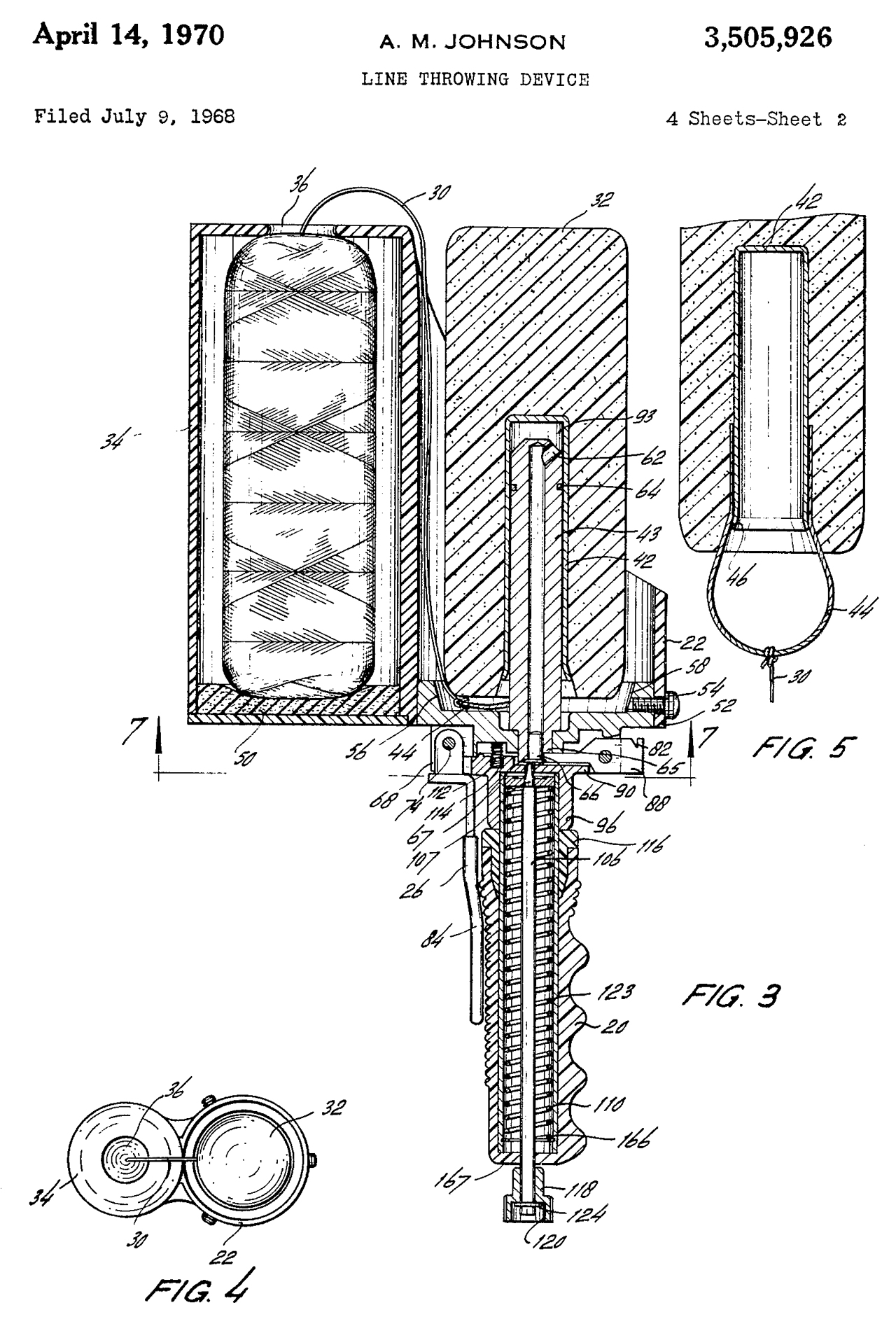
3505926
Line Throwing Device, A.M.
Johnson (Scientific Prod Corp), Apr 14 1970, 89/1.34
; 102/504; 42/105- similar to the hand held dog training
duck launchers
Uses the same spigot and dog training
dummy as the Retriv-R-Trainer plus adds a canister of
interiorly wound line.
shoulder stock also contains a latch
type trigger release that works with the knob at the
bottom of the Retriv-R-Trainer.
|
Called by:
4077349 Line boy Mar 7, 1978 - permanently boat mounted for
throwing lines to dock
4098015
Retriever training gun with pistol type handle,
Andrew
W. Walbe, Jul 4, 1978, - looks like a couple of
Retriev-R-Trainers side by side.
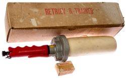
Calls: 3004360
Retriev-R-Trainer
|
|
|
 |
Targeteer (Can Cannon)
|
|
3004360
Target Projecting Device Utilizing a Can and a Blank
Cartridge, A.M.
Johnson, Oct 196, 42/105 ; 42/34 - beer
or soda can shooter - Basis for the Retriv-R-Trainer
The RL
Line Launcher is based on a dog training device
but adds a line in a bottle that's rewindable.
But . . . $500 (2015)
|
|
Targeteer Powder Actuated
12oz Can Target Launcher w/ Box
It's
a Trap! 029: Targeteer Can Launcher, 28:26 -
Webley, shows 3004360, uses Hunt Wilde bicycle grip,
Modern cans?: Rotella Tomatoes, Campbell's Cheddar
Soup
|
|
3186119 DEVICE FOR PROJECTING AN AERIAL TARGET, Jun 1965
42/105
; 124/41.1; 42/98; 42/99- magnet holds tin beer can launched
from revolver shooting blanks
3415438 DEVICES FOR PREVENTING DROP-FIRE, (United Shoe
Machinery), Dec 1968 - safety device for explosive fastener
driver
3505926 Apr 1970 <see above>
3534492 FIREARM GRENADE LAUNCHING ATTACHMENT, S.A. Amster
(Federal Labs), Oct 20 1970,
42/105 - smoke can type
grenade launcher
3623257 RIFLE HAND GRIP DEVICE, Nov 1971 - vertical grip on
forend of rifle
3656399 STOCK AND TRIGGER MECHANISM FOR LINE THROWER, O.W.
Hill, Apr 1972
89/1.34 ; 42/105; 42/72 - works with
line thrower that looks like retriever dog trainer
3672084 REINFORCED PISTOL GRIP, Frank A. Pachmayr (Mershon
Co), Jun 1972 - rubber molded over sheet metal stamping
4154013 Device for training retriever dogs May 15, 1979 - pistol
type
Calls:
2883781 Combination Stabilizer, Recoil Break, Flash Hider, and
Gernade Launcher for a Firearm E.M. Harvey (Army), Apr 1959, 42/105
; 89/14.3 -
3004360 <see elsewhere>
3176422 ANTI-JAMMING MEANS FOR REVOLVERS, Apr 1965
3186119 <see elsewhere>
3392469 METHOD OF OPERATING A REVOLVER FOR SHOOTING A
PROJECTILE ATTACHED ON THE Outside of the Barrel Thereof, U.
Dubini, Jul 1968 -
3505926 <see elsewhere>
3731418 SMALL FIREARMS WITH EXCHANGEABLE Barrel, M.
Biekenhagen, May 1973, -
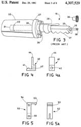
| 4307529
Remote control bumper launcher for training retrieving
dogs Dec 29, 1981, -Fig 3 (Prior Art) 3004360 - This
product adds remote control to the 3004360 |
|
4341030 Hunting dog training device, R.L. Little (Little
Launcher), Jul 27, 1982 - replacement barrel for pistol
Calls:
2432539 Grenade Launching Tube and Auxiliary Cartridge
Therefor, C.R. Olsen, Dec 16 1947, - maybe spigot for M14
Rifle
2883781 <see eleswhere>
3004360 <see elsewhere>
3007271 Device for Throwing Grenades by means of Firearms,
E.W. Brandt, Nov 1961, - to work with rifles fitted with flash
suppressors
3176422 <see elsewhere>
3186119 <see elsewhere>
3243909 Grenade Launcher, N. Kotikov, Apr 1966, - for use with
cylinder bored shotguns (riot guns)
3392469 <see elsewhere>
3415438 <see elsewhere>
3496580 INFLATABLE AND RECOVERABLE LIFESAVING PROJECTILE
APPARATUS,
3505926 <see elsewhere>
3534492 <see elsewhere>
3618244 METHOD FOR FIRING PROJECTILES UNDERWATER, -
spear gun
3623257 <see elsewhere>
3656399 <see elsewhere>
3672084 <see elsewhere>
3713394 SMOKE SIGNAL DEVICE, (Navy) 102/334 ; 42/105 -
fits over revolver barrel
3717946 DEVICE FOR SHOOTING A PROJECTILE, - fits revolver and
works with ball ammunition instead of blanks
3731418 <see elsewhere>
3981225 Launcher arrangement for rocket powered round
4098015 Retriever training gun with pistol type handle
4154013 Device for training retriever dogs
D290731 Buoy marker launcher, Albert E. Canady Jul 7, 1987
Calls:
4263835
Sonobuoy launcher system
(Navy) Apr 28, 1981- A pneumatic restraint and ejection system
4279025 Releasable airborne buoy Jul 14, 1981
4718320 Towed decoy system Jan 12, 1988
4741243 <see first patent>
4784035 Remotely actuated tow line throwing device Nov 15, 1988
4799906 Rescue apparatus Jan 24, 1989 - rifle custom made firing
blanks, spool on gun
4852455 Decoy system Aug 1, 1989 - spool in projectile with axis
coaxial with centerline
4912869 Net gun Apr 3, 1990 - four barreled rifle
5460155 Behavior deterrence and crowd management Oct 24, 1995 -
very similar to the retriever launcher, but can have taser wires
spooled from projectile
5592770 Shotgun mounted launching device and launching
projectile Jan 14, 1997 - spigot attaches to choke threads on
shotgun for retriever dog training
5811713 Apparatus for launching projectiles Sep 22, 1998 -
spigot attaches to choke threads on shotgun
5915694 Decoy utilizing infrared special material Jun 29, 1999
6116606 High speed glide target Sep 12, 2000
6244261 Line installation tool Jun 12, 2001 - pneumatic rifle
type launcher
6499407 Packaging method for infrared special material Dec 31,
2002
6510798 Packaging method for infrared special material Jan 28,
2003
6571714 Silicon window infrared augmenter Jun 3, 2003
6634299 Gas generator Oct 21, 2003 (TRW) - for air bag
LINE THROWING GUN AND CARTRIDGE, Jun 1971 - sub-caliber adapter
for shotgun or use shotgun blank
1072968 Means for Carrying Life Lines, Sep 1913 - cannon for
throwing life lines on ship
1072969 Means for Carrying Life Lines, Sep 1913 -cannon for
throwing life lines on ship - line in projectile
2373364 Bolas Projectile, Apr 1945 - type of anti aircraft shell
that has spreading wires
3780662 RADAR REFLECTOR DEPLOYMENT METHOD, Dec 1973 - rocket
unspools long metalized glass fiber
3863380 ILLUMINATED FISHING LURE WITH LINE ATTACHMENT, Feb 1975
3918190 METHOD FOR ILLUMINATING ORGANIC Nov 1975
4326657 Optical fiber dispenser Apr 27, 1982
4649660 Fishing float assembly Mar 17, 1987
4653379 Filament deployment means Mar 31, 1987
4656945 Helicopter destruction system employing cables Apr 14,
1987
------------------------------------
Type 89 Knee Mortar
YouTube:
Type 89 Knee
Mortar Interesting way to adjust range - might work for a
tennis ball line thrower.
These are intended to be used for clearing trip wire mines (de mining, land mines). But
might be used just as a line launcher.
It's intended to be launched from any of the M16 - M4 style rifles. The first
time it's used a normal ball round can be used, but all
subsequent rounds need to be .223 blanks.
Fig 1
|
Fig 2
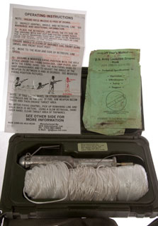 |
Fig 3 rear bore is about 22mm (0.865")
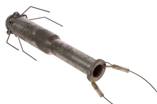 |
Fig 4 standard 1/4" hex, but extremely
tight
 |
|
|
2388749
Cord holder for line throwing gun,
Pierre Alfred T La,
Harrington & Richardson
Arms C, 1945-11-13 - container for holding the cord
for a line throwing gun.
Air Boss
This is an air powered line shooter that uses a 2 oz lead
weight as the bullet. That's to say the PVC pipe used as
the barrel has an I.D. that's just a little larger than the OD
of the lead weight. He uses a simple 90 degree ball valve
to release the air rather than the more complex-expensive
sprinkler valve as used on the Tennis Ball
Line Launcher above. Sells for about $60 but that
includes neither the fishing reel nor line.
PCPTanks
Pre-Charged Pneumatic (Wiki: PCP)
air guns come in two varieties. Some have built-in air
tanks, and some use external replaceable air tanks. Then
there are larger SCUBA tanks used to charge the gun or it can be
charged using a high pressure air compressor. There is
also the very common 12g CO2 Powerlet cartridges (Wiki) used
for BB and pellet guns. These tanks may be the basis of a
line launcher. Another possible source of propellant is
from the world of Paintball (Wiki).
After reading about the Airsoft situation and how liquid CO2
causes a number of problems, the compressed air tanks for PCP
air guns or the HPA (Wiki: High
Pressure Air) tanks for Airsoft seem like a better way to
go.
The Alloy tanks are lower in cost than the carbon fiber tanks.
Material
|
Liters
|
PSI
|
$
|
Al
|
0.22
|
4500
|
36
|
| Al |
0.25
|
4500
|
32
|
| Al |
0.30
|
4500
|
37
|
| Al |
0.5
|
3000
|
43
|
C
|
0.35
|
4500
|
138
|
C
|
0.42
|
4500
|
135
|
C
|
0.58
|
4500
|
170
|
C
|
0.80
|
4500
|
178
|
C (SCUBA)
|
3.0
|
4500
|
270
|
SCUBA Tanks (Wiki)
are between 3 and 18 liters water capacity in size.
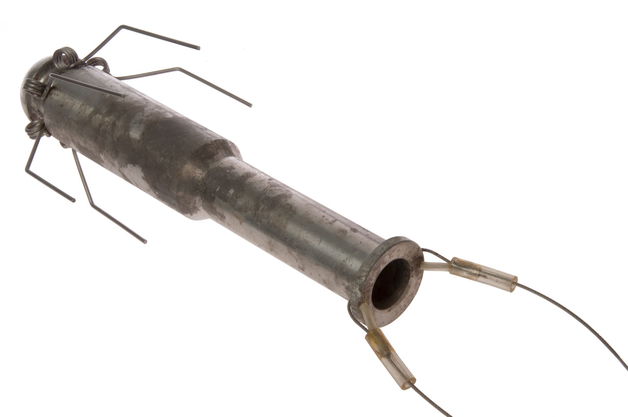
TCI 651T H.F. Antenna
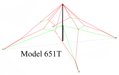 |
Red: top of the delta loop radiating wires.
Green: mast guy ropes and Catnary Rope Assemblies
Gray: bottom of loop 78' (ground) wires.
The guy stakes are in a square pattern 55' on a side.
Where the two sides of a delta loop join they also connect
to the ground wire.
From that point there's a green insulating rope to the
corner stake (the drawing above shows
red wire going to the ground stake, but that's a drawing
error.
The horizontal green insulating rope ties between adjacent
delta loops are about 8 feet long.
If you look at the central angel between the top delta
loop wires they are all about 45 deg apart. |
651T (MIL AS-3791/G) and F
The antenna is intended for ground wave and sky wave
communications with omnidirectional coverage; the
application for sky wave communications is over
short-to-medium ranges.
The radiating element consists of two fan-delta curtains
supported on a common tubular aluminum mast and placed at
90° to each other. Each delta is driven by its own balun
which, in turn, is driven by a power divider and 90°
hybrid network. A lightweight aluminum tilt-up mast
permits fast erection.
A special feature of the Model 651 is the care taken to
provide EMP (White
paper) protection in accordance with the
requirements of DRCPM-8223. This protection is given
by good grounding, the use of pulse arrestors across the
balanced terminals of the matching units, and a robust
design able to withstand high voltages with a margin of
safety.
These features and the construction materials make the
antenna fully suitable for military and emergency type
applications.
|
Specifications
Model 651T (MIL AS-3791/G) & F
Polarization..............................Vertical,
Circular Hor. comp.
Impedance ............................... 50 ohms nominal
VSWR ....................................... 1.5:1 maximum
Frequency................................ 2–30 MHz
Power Handling ....................... 400 Watts Avg/PEP
Mast Height.............................. 27.5 ft (8.4m)
Environmental ......................... 100 mi/h (160
km/h) no ice
Performance ............................ 60 mi/h (96 km/h)
1/2” radial ice
Erection Time 651T ................. 1 hour, 4 men
|
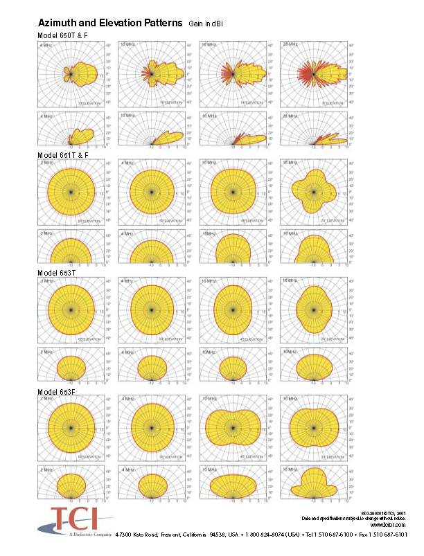
The vertical pattern at low
frequencies where NVIS mode works all show signal going straight
up, but the 650 in the same data sheet shows nulls straight up.
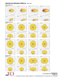 |
650T & F
651
653T
653F
|
Click on pattern image to see larger image.
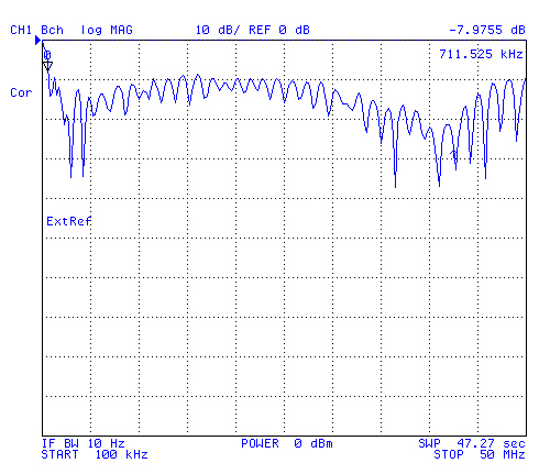
When looking at the return loss of the antenna from 0.1 to 50 MHz
it's below 10 dB, better than 2:1 VSWR. This is true for
much higher frequencies.
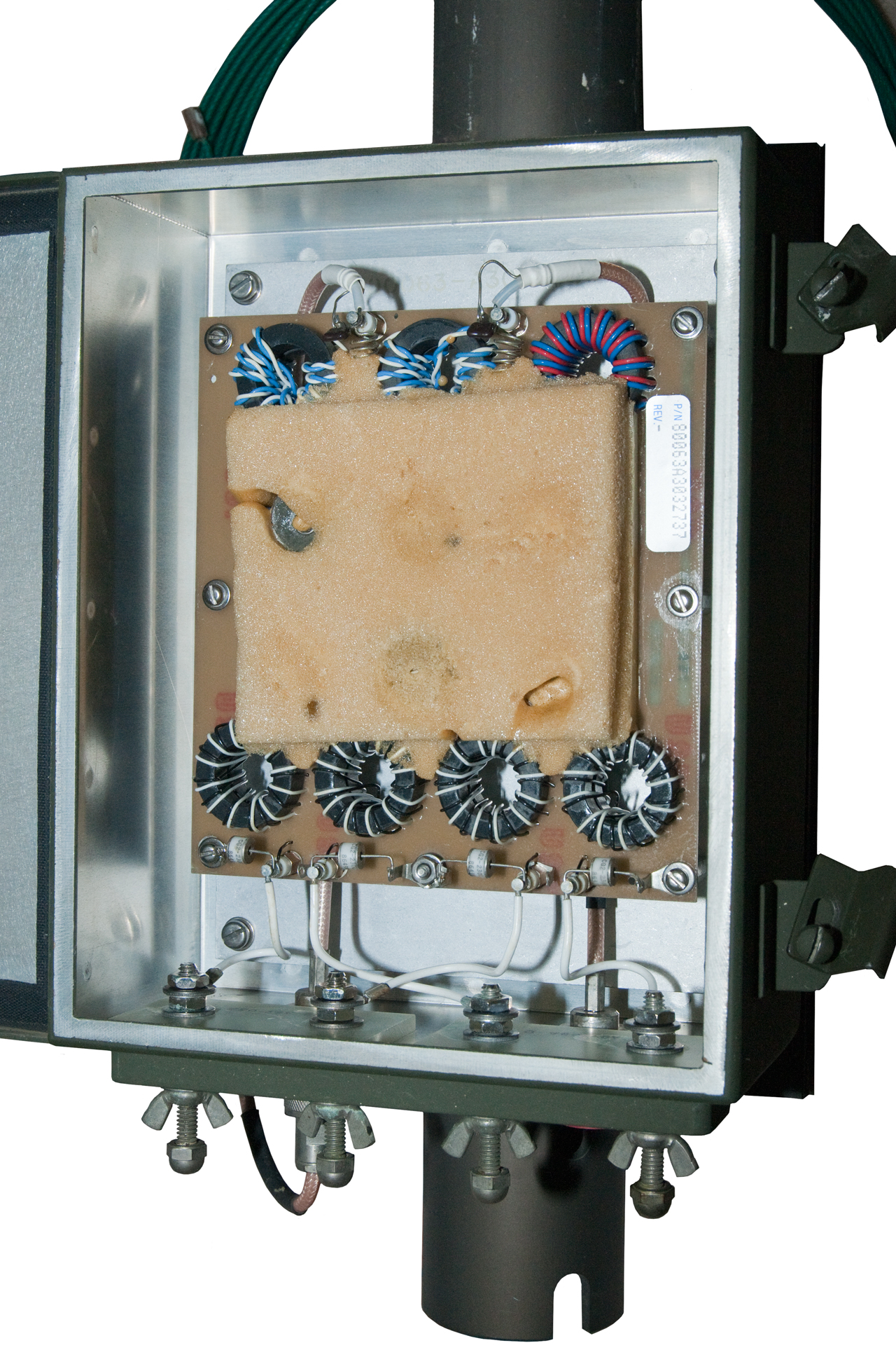
The toroid inductors in the mast head network make a lower limit
on good match around 700 kHz.
But, just because the match is good over a very wide range of
frequencies that does not mean the antenna radiates well over that
same range. Note the mast head matching network contains two
very large power resistors.
You can't see all of the
antenna from any single location so it's very difficult to
photograph. Having green coated wires and a green
forest background also makes it difficult to see.
|
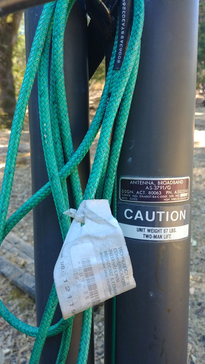
Antenna, Broadband
AS-3791/G
Dsgn. Act. 80063 p/n: A3023748
Contr. No. DAA807-84-C-D0001 s/n:
1nnnA
Mfg. 30103 NSN: 5985-01-254-0698 |
|
Looking East before sunset.
|
|

|
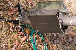
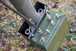
Mast Head
The four terminals on the BALUN box have phase angles of
0, 90, 180 & 270 degrees and it's
important that they are connected sequentially to the four
antenna wires. Hence the blue tape flags.
|
|
Intended for ground and sky wave
with omnidirectional pattern. Radiating element consists of
two fan-delta curtains supported on a common tubular aluminum mast
and placed at 90 degrees to each other. Each delta is driven
by its own balun which, in turn, is driven by a power divider and
90 degree hybrid network. Features: Fast erection and EMP
protection.
One of the places this antenna was used is the TRC-179 Force
Terminal which is part of the "Regency Net" Communications
system. The AN/GRC-215 Team Terminal is another part of the
system.
For more about the TRC-179 see:
Mark's
Green Pages:
AN/TRC-179
"Regency Net" HF/SSB Transmitter/Receiver
Communications Terminal AN/TRC-179(V)1 (NSN 5895-01-156-0411) and
Communications Terminal AN/TRC-179(V)3 (5895-01-202-8672)
TM 11-5895-1218-12
Photos
Description
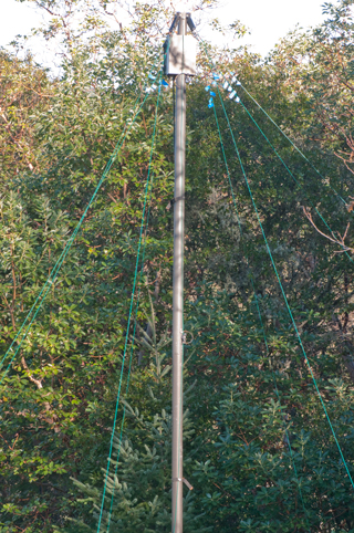
The antenna consists of two crossed delta loops. The bottom
of each loop is 78 feet long (Item 18). These are at right
angles to each other and where they cross are connected together
and to ground. At the center of the bottom is a grounded 30'
mast (Items 6, 7, 8 & 9). If it was a single wire loop the top
two elements would each be 50 feet long and the total loop length
would be 78 + 50 + 50 = 178 feet (54 meters) which is a wavelength
at 5.5 MHz or a half wave at 2.7 MHz. But each of the top
legs of the delta is composed of two wires that are longer than 50
feet that have an insulating rope (Item 22) attached at their
midpoints. So the loop length is a little longer (maybe a
half wave at 2 MHz). There are four antenna ends at the top
of the mast that are connected to four separate terminals on the
feed BALUN - hybrid assembly (Item 4). It has a 50 Ohm feed
line and outputs at 0, 90, 180 and 270 degrees relative phase that
feed the four antenna elements. In order to work as a hybrid
the assembly includes a couple of high power resistors.
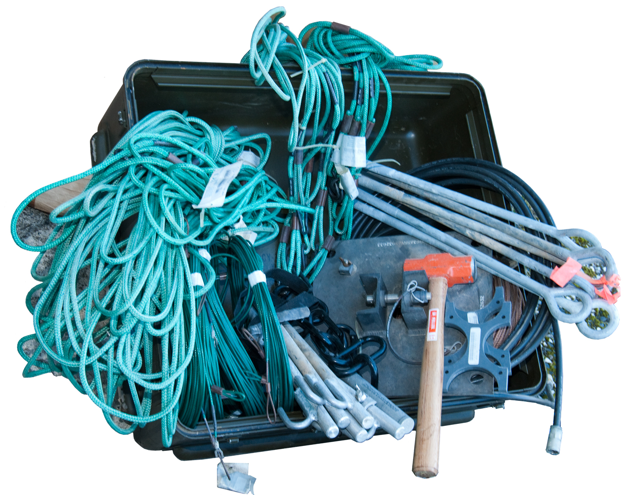
Bill Of Materials
| Item |
Description |
A
p/n |
p/n |
Qty |
| 1 |
|
|
|
|
| 2 |
|
|
|
|
| 3 |
|
|
|
|
| 4 |
Balun
Box |
|
|
1 |
| 5 |
|
|
|
|
| 6 |
Base
Plate |
A3032633 |
1046-ASY-01A |
1 |
| 7 |
Mast
#4 (Bottom) |
A3032630 |
|
|
| 8 |
Mast
#3, #2 |
A3032636 |
|
2 |
| 9 |
Mast
#1 (top) |
A3032641 |
|
|
| 10 |
|
|
|
|
| 11 |
Gin
Pole, Handle Assy |
|
|
|
| 12 |
Reel
1 |
A3032718 |
|
|
| 13 |
Reel
2 |
A3032719 |
|
|
| 14 |
Radiator
Assy Reel1-2 |
A3032738-1 |
512-RAD-01A |
1 |
| 15 |
Radiator
Assy Reel1-1 |
A3032738-2 |
512-RAD-02A |
1 |
| 16 |
Radiator
Assy Reel2-2 |
A3032738-3 |
512-RAD-03A |
1 |
| 17 |
Radiator
Assy Reel2-1 |
A3032738-4 |
512-RAD-04A |
1 |
| 18 |
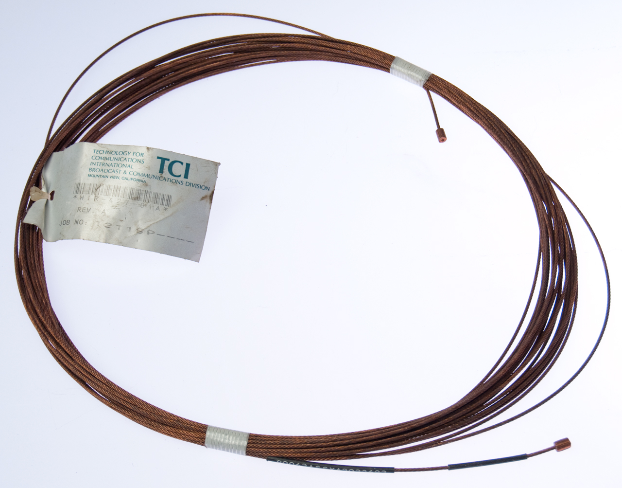
Bare
Gnd Wire 78' Reel1-3, Reel2-3
|
|
|
2 |
| 19 |
55'
Layout Wire

|
A3032623 |
427-WIR-01A |
1 |
| 20 |
Guy
Rope |
|
865-GUY-01A |
4 |
| 21 |
Erection
Rope |
|
365-GUY-03A |
1 |
| 22 |
Catnary
Rope Assy |
A3032640 |
483-CAT-01A |
4 |
| 23 |
Curtain
Tension Ropes |
|
021-TIE-01A |
4 |
| 24 |
Mast
Coax |
A3032624 |
253-CBL-01A |
1 |
| 25 |
|
|
|
|
| 26 |
Guy
Stake (Anchor Bolt) |
A3032720 |
|
4 |
| 27 |
Base
Plate Stake |
A3032625 |
|
3 |
| 28 |
Base
Plate Stake
w/Wire Term |
A3032626 |
|
1 |
| 29 |
Bar,
Wire Reel |
A3032621 |
|
|
| 30 |
CG-3874/TRC-179(V)
150' Coax |
|
|
|
| 31 |
2#
(32 oz) Hammer |
A3032721 |
|
|
| 32 |
Bag
1 |
A3032722-1 |
|
1 |
| 33 |
Bag
2 |
A3032722-2 |
|
1 |
| 34 |
Mast
Shipping Straps |
A3032672-2 |
|
2 |
| 35 |
Mast
Shipping Spacers |
A3086743 |
|
2 |
| |
Guy
Tie Wire |
A3032639 |
|
4 |
Installation
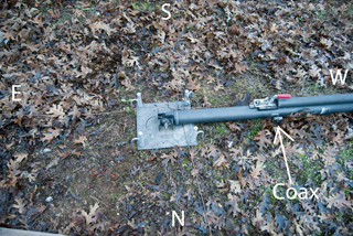
There are a couple of fine points I'd like to add. First is
to position the coax on the North side of the mast to protect it
from the summer sun.
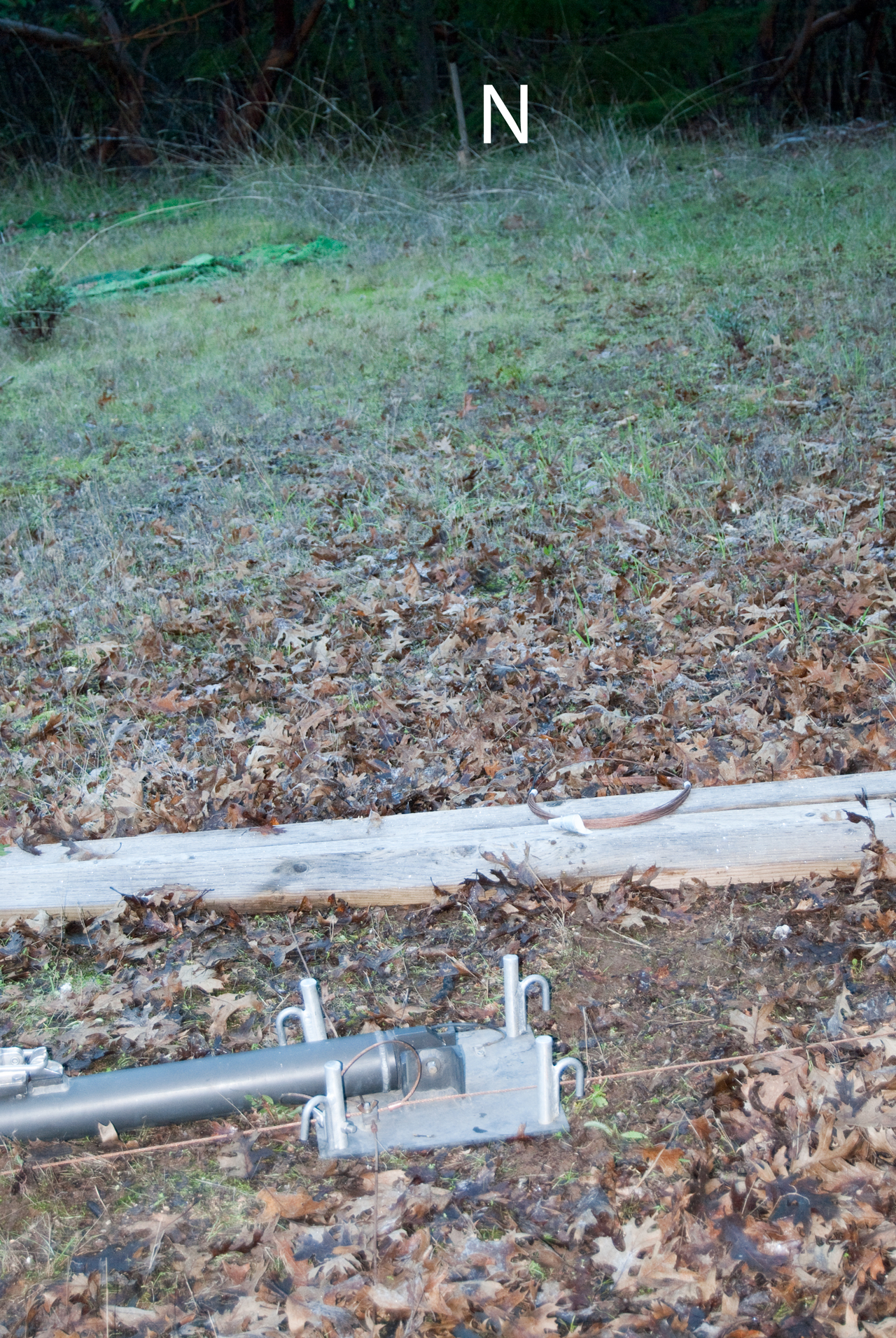
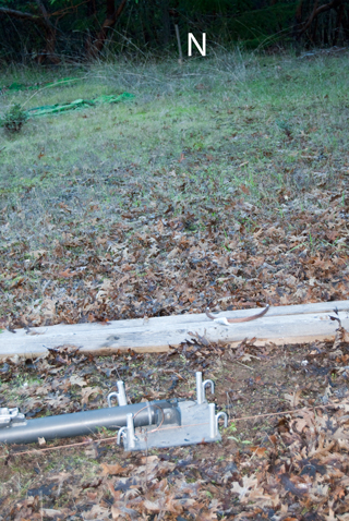
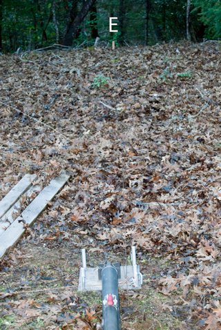
Second the intersection of the two ground wires
is offset from the hinge point of the mast on the base
plate. It would be good for the mast starting position on
the ground was on the opposite side of the hinge point so that
the guy ropes will be slack until the mast is erect.
This is a non issue when the guy anchor points are made at 0, 90,
180 and 270 degrees all centered on the mast pivot.
|
|
The coax is facing North, will be shielded from Noon Sun.
But . .
Mast is on
wrong side of base plate, it needs to be disconnected
and moved so it's pointing East. |
 |
|
|
Leitz
115A transit setup over mast pivot.
Top pivot set to 0.
Bottom pivot aimed to the West stake
(where mast is pointing). Then bottom locked and
top turned to 90 degrees. The South stake can be
seen through the transit. (to the left of it's eyeball
location)
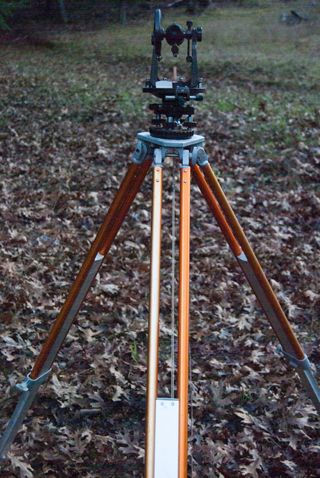
This stake was off a few feet.
Plumb bob is over hinge.
|

|
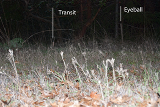
The North eyeball stake was
off maybe 6 to 10 feet. It makes sense.
The West stake was located using the mast as a
pointer. And back sighting to the East stake was
good to a foot or so.
But eyeballing the North or South stakes requires
measuring an angle is where the problems show up.
The tall stake on the right is the eyeball North and the
one to the left is the transit located one.
|
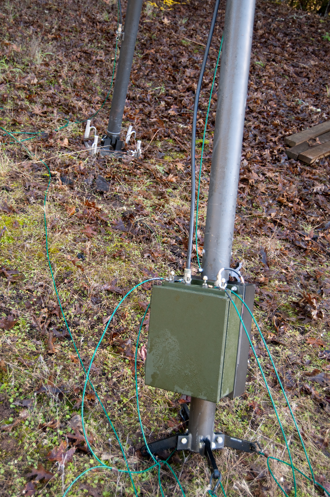
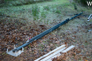
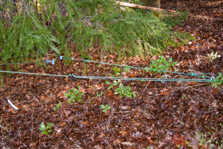
All the mast sections are in place, but neither the BALUN
nor antenna wires have been attached.
The vertical green rope is used to pull down the hinged
mast.
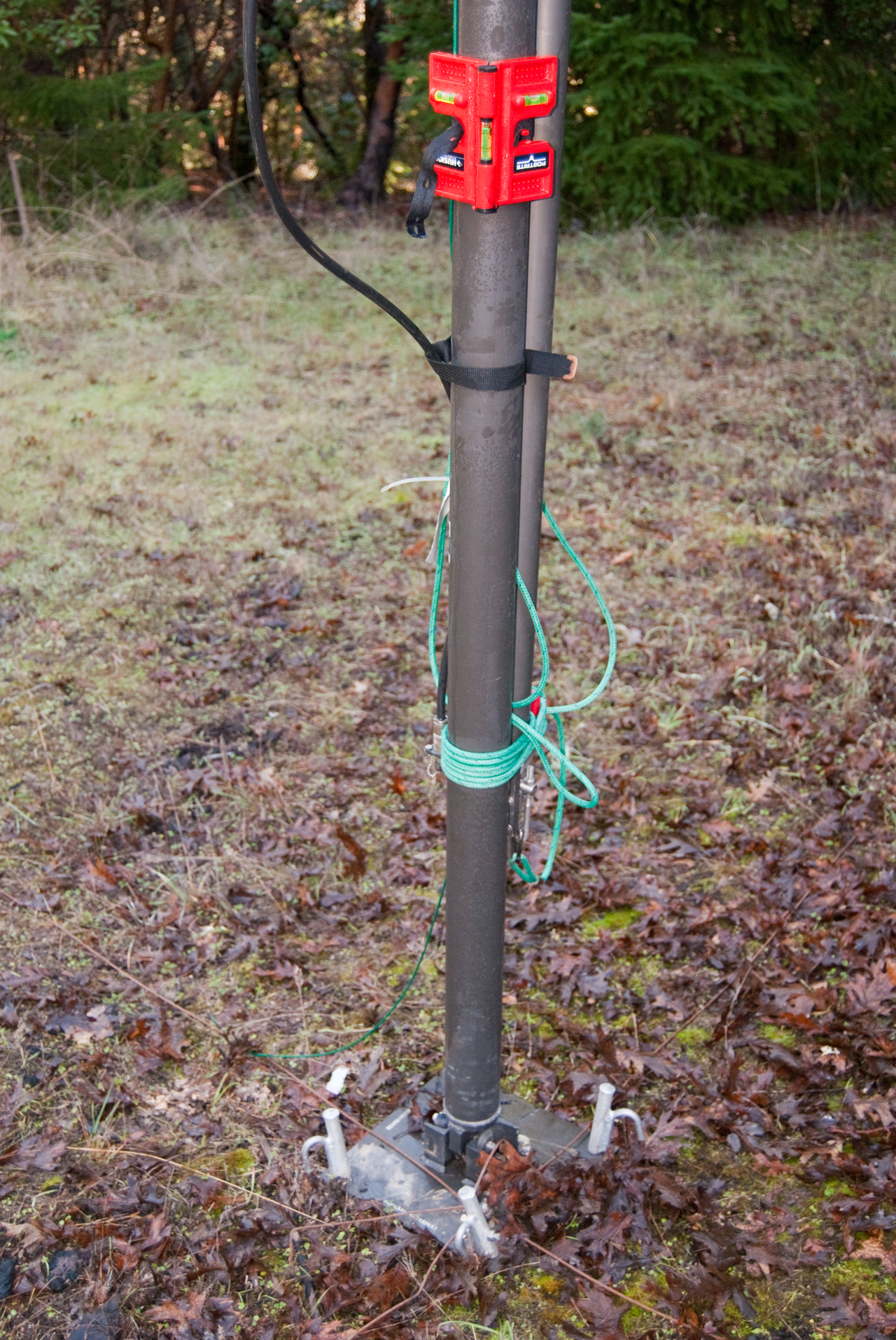
The red thing about 6 feet above the ground on the main
mast is a fence post level that makes it easy to plumb the
mast.
The Oak tree has some very small branches touching to top
of the mast.
Tips of Oak tree branches at top of Gin Pole.
 |

|
BALUN has 4 antenna
terninals and 4 wire antenna support snaps (same as guy
rope snaps).
The 4 terminals (1, 2, 3 & 4) have phase relation (0,
90, 180 & 270 deg) making for a circular polarization
signal.
|
|
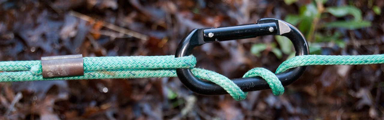
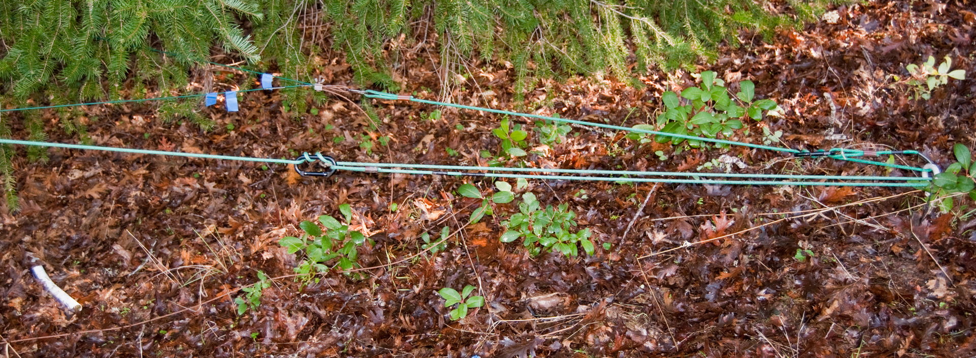
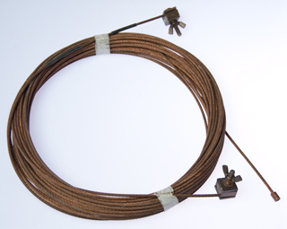
Detail of Guy rope at
anchors.
Snap ring looped through Anchor bolt then 3 times the rope
has been put through the snap.
Anchor to
Left
Mast to Right.

|
It
turns out that the small tree branches foul the antenna
wires and prevent properly getting them in position.
So the base has been relocated by taking the mast down to
the ground,and rotating the mast about the BALUN so the
base is now about six feet from where it started and well
clear of the tree. This required, pulling the mast
base stakes (with a five foot TV mast), disconnecting the
shourt guy rope at it's anchor bolt, then the ground wires
were re-positioned, the guy bolts pulled (w/TV
mast). I discovered the type-N cable that runs from
the BALUN to the base of the mast is defective when
installing it, but because of the tree problem decided to
bring it inside for repair rather than make the repair
outside.
|
|
|
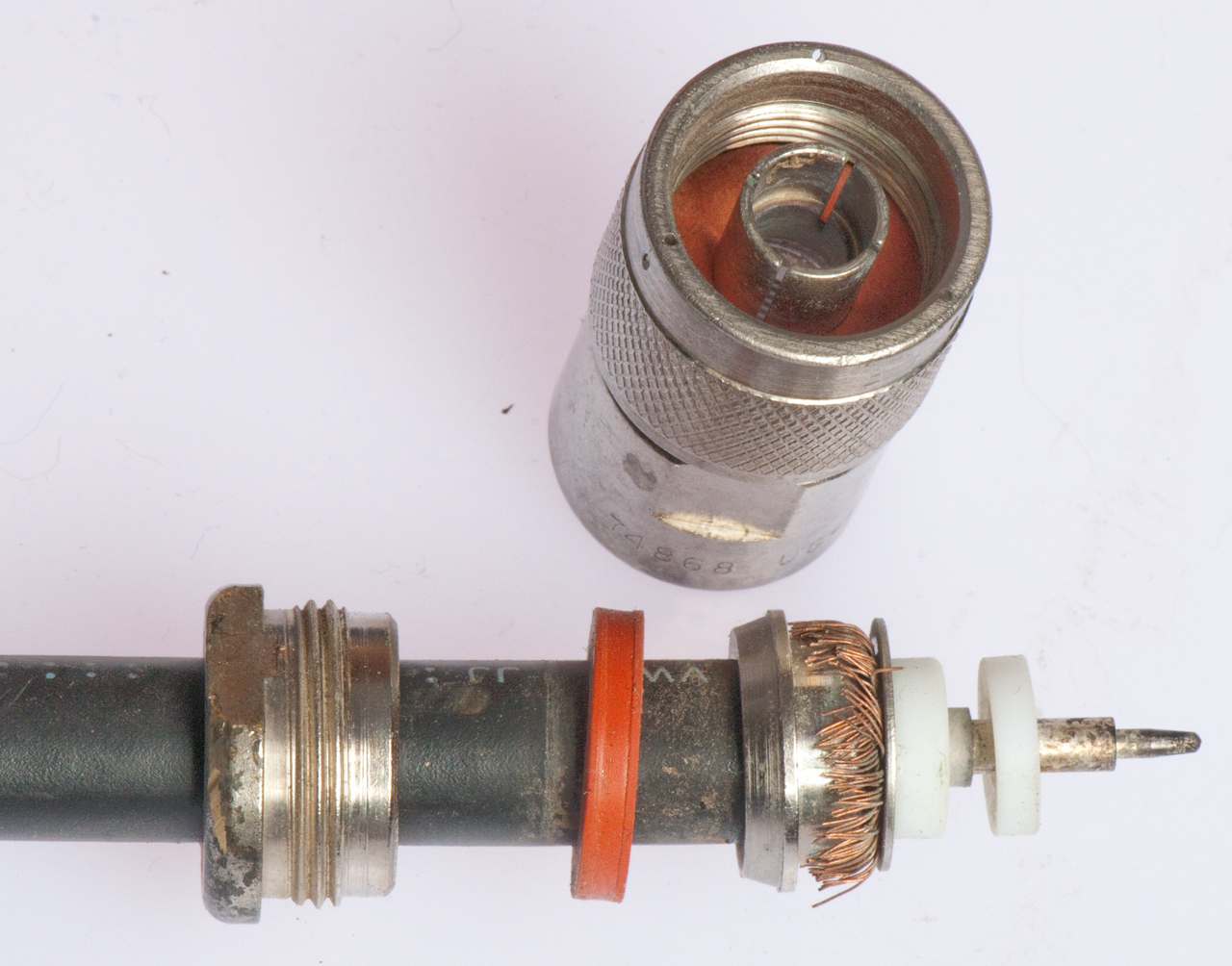
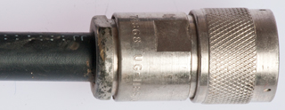
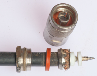
I had downloaded the installation
instructions for the UG-1185 type-N male coax plug,
took the photo at far left and confirmed that the
connector could be rotated on the coax, then opened it up
in preparation to making the repair.
But I lucked out, instead of finding a bunch of short
shield wires inside, everything looks OK. There was
a clue in that it was very easy to open.
The problem was the clamp nut was loose.
|

|
Before tilting mast up blue tape flags (1, 2, 3 & 4)
were put on the wires so they could be identified from the
ground.
|
|
East (2) Anchor Wiring
Detail
|
Plumb Mast using fence post
level.

|
|
The
100 foot coax cable reaches from the antenna to just past
my front door, but is about 20 feet short of making it to
the rack mounted HP 4395A Network -
Spectrum - Impedance Analyzer. Wouldn't you
know I'm missing the adapter needed to connect the two
cables and Radio Shack no longer carries it (Type-N
female-female barrel). For lack of a horseshoe nail
. . .
|
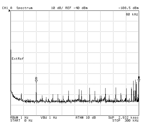
Spectrum Analyzer Plots
There are a lot of signals.
The antenna is working well. A much better test would be
to use it with a
chirp receiver, or
a regular short wave receiver tuned to each of the NorCal DX
beacons.
Made with HP 4395 10 Jan 2012 starting about 5:30 pm PST.
6 pm
|
Noon
|
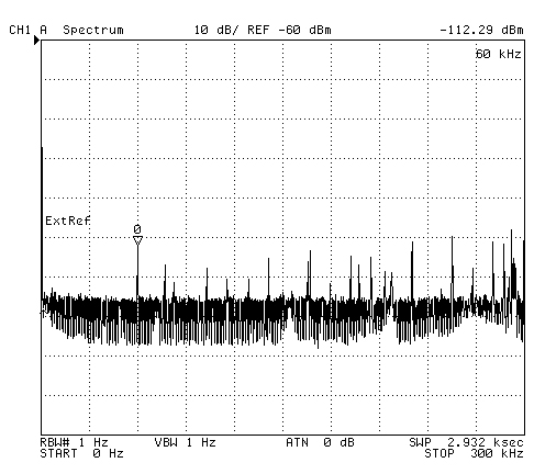
0 to 300 kHz
This is amazing performance what a signal at 24.75 kHz is
seen and WWVB at 60 kHz is about 20 dB above the noise at
8 pm local time.
|
0 to 300 kHz
|
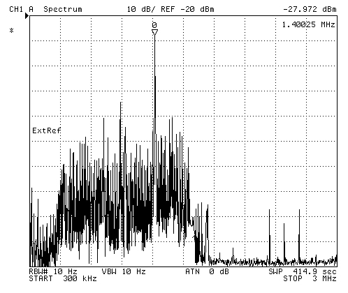
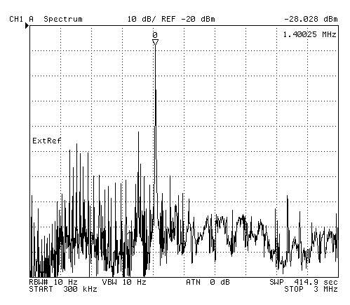
Medium Frequency 300 kHz to
3 MHz
KUKI the local AM station at 1.4000 is the strongest.
|
Medium Frequency 300 kHz to
3 MHz
|
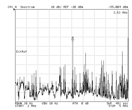
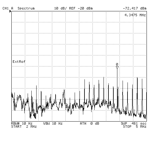
2 to 5 MHz
3.53 MHz is the strongest signal
|
2 to 5 MHz
|
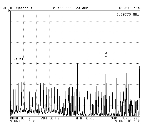
5 to 10 Mhz
7.3875 MHz is the strongest signal
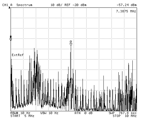
|
5 to 10 Mhz
|
10 to 15 MHz
Strongest signal at 13.66875 MHz (13.670?)
Band quieter, shifted power level reference from
-10 dBm to -40 dBm.
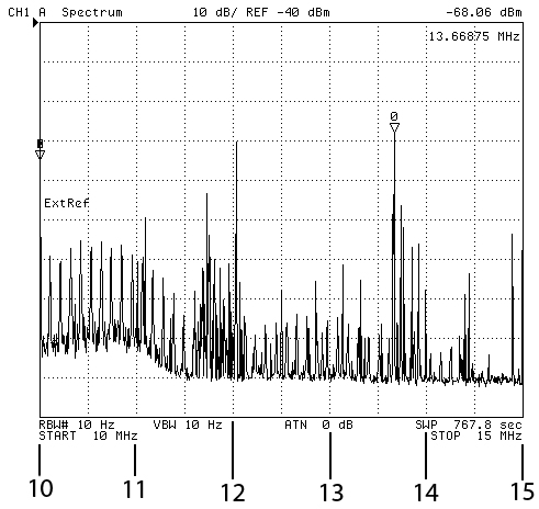
|
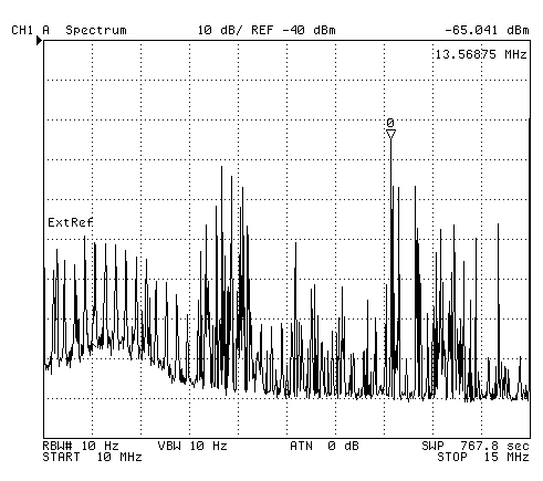
|
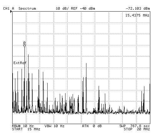
15 to 20 MHz
Strongest signal 15.325 Mhz.

|
15 to 20 MHz
|
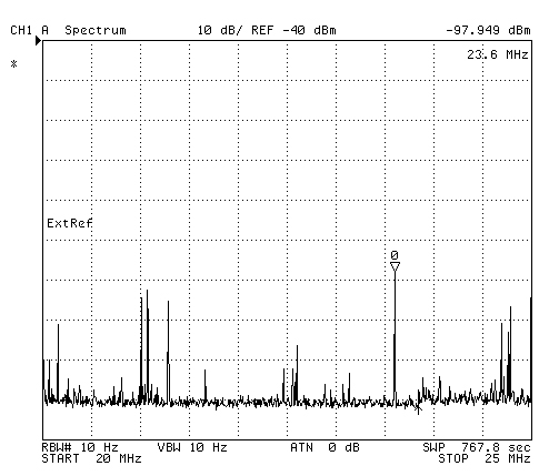
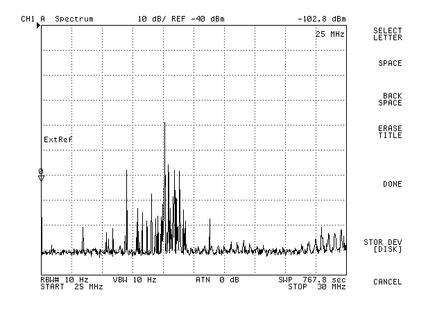
20 to 25 MHz
Strongest signal at 23.6 with WWV at 25 not far below
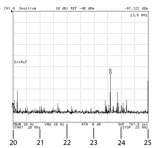
|
20 to 25 MHz
This plot was saved before it finished. Notice the
right 2-1/2 squares are the
same as the plot above and you can see the up arrow
cursor.
|
25 to 30 MHz
Strongest signal 26.4 Mhz with WWV at 25 MHz not far
below.
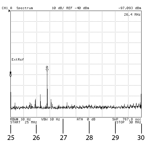
|
|
Operation
The ICOM 706 MkII G works with the TCI
651T on the 80 meter army radio net (3996 kHz USB, so the
antenna is working OK.
The burned spots in the foam around the toroids indicates over
heating, but apparently not permanent damage.
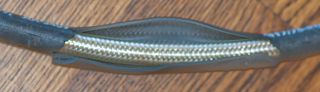
Problem with Coax - July 2013
There are splits in the coax jacetk allowing you to see the
shield braid. At first I thought these were caused by
negligent use of the weed mower, but now think it's just the Sun
breaking down the jacket.
Raychem Repair
To cover the place where a lot of the jacket is torn I used
some Raychem shrink tube. This tube has an I.D. of about
7/8" and will just clear a type-N male connector, but not the
wire ring that holds the end plug which needed to be removed to
slip the tube on. The tube is marked:
Raychem WCSM 20/6 EX20781-13
It has an adhesive on the inside that melts and forms a gray
colored bead at the ends after shrinking the tube using an
industrial type heat gun.
But this is just a patch. The long term fix is to get the
coax out of the Sun.
Trenching and pulling the coax into conduit is an expensive and
back breaking solution with the risk of cutting other in ground
utilities (water main, sprinkler pipe, storm drain pipe).
Maybe a better solution is to use pipe insulation sleeves that
have a slit along the long dimension?
Using HF NVIS for Emergency communications in addition to VHF.
Coden Envoy radios
(one at court house, one vehicle mounted).
Direct Burial + UV Resistant
Need to measure how long to order. Only 5 of the 15 coax
types they carry have the needed properties for this
application.
Table of DX Engineering Coax Cables that are rated for direct
burial and are UV resistant.
Wire Antenna Patents
6791508 Wideband (NVIS) conical
spiral antenna, Sonja
A. Berry, James
R. Gilbert (Boeing),
Jun 6, 2002,
343/895,
343/749,
343/881
Also interesting 48 citations and referenced by
15 patents. 46' x 105' with 33' central mast
4498084
Four wire dual mode spiral antenna, William L. Werner, Raymond H.
DuHamel (TCI), Feb 5, 1985, 343/792.5; 343/891; 343/895 (
TCI 545?)
Calls:
3376577
Vertical radiation spiral
antenna, Dean
Kennedy Peter (Granger
Associates), Nov 15, 1965,
343/886,
343/895 - Vertical sounding 2-15
MHz 30' hi x 200' dia.
2958081 Unidirectional broadband
antenna comprising modified balanced equiangular spiral,
Dyson
John D (Univ
Illinois), Jun 30, 1959,
343/895,
343/908
Point is at the top, should be at the
bottom (see 3376577 for explanation).
3683390
HF Broadband Omnidirectional Antenna, Cory; William A. Kennedy,
Cory; William A. Kennedy (Collins), Aug 8 1972,
class: 343/792.5; 343/798;
343/809; 343/891 - tall mast Log Periodic pointing up
3906509
Circularly Polarized Helix and Spiral, Raymond H. Duhamel,
Raymond H. Duhamel (not assigned), Sep 1, 1975, 343/895
Antenna Construction with Effectively Extended Radiator Elements,
William L. Wermer (Grainger Assoc), Nov 2 1971,
343/792.5; 343/802; 343/884;
343/890 - this looks like the gigantic log periodic beam that
was later sold by TCI
3368319
Tall Column Structure of Connected Sections with Warren
Cross-bracing and Legs of Channel Section, Werner & Thomas
(Grainger Assoc), Feb 13 1968,
52/637; 52/148; 52/651.02; 52/694
Other Wire Antennas
Links
Coleman's Surplus - where I
got these titled: "Support System for Camo Netting" and got
the Aluminum poles, not the fiberglass ones
The Mast Company - sells the
poles and they have made some accessories like guy rings
Sherill
Big Shot Item #LT41001.LT41009,LT41010 - giant slingshot -
120' vertical reach
Tetra
Line Thrower - uses special .308W blanks.
WiNRADiO - AX-12B
Wide-Band Surveillance Antenna System - covers Band 1: 0.15-30
MHz, Band 2: 30-100 MHz & Band 3: 100-1500 MHz (3ea Type-N
connectors)
Back to Brooke's PRC68, Products for Sale,
Military Information, Personal
Home
page created 16 Nov 2008.