Orion Electronics Ltd.
Cellular Base Station
ST616-CBS
© Brooke Clarke 2014
Got this shortly after posting my web page Spying on Cellular Phones. It's made by Orion in Canada and their web page says "Innovative surveillance solutions for North American law enforcement and government agencies" and not much else. So I expect this is a box for spying on cell phones.
The idea is that any cell phone that is within range of this unit will think it's a cell tower and will use it to place new calls or will transfer a call in progress to this "new" cell tower. Note that there's a connector on the back "phone line" so the cell phone call gets routed to a land line, i.e. the person on the cell phone does not know their call is being intercepted. This might be called a "man in the middle attack" (Wiki).
Applicable Cell Phones. My old Sony-Erickson K800i does not do GSM-850, but the Motorola Razr (Wiki) and Electrify (Wiki) do.
Important Note: Modern cell phones have the ability to work on many frequency bands and using many protocols even though the phone may be subscribed to one frequency - protocol, it still will respond to GSM-850 if that's one of it's capabilities.
Photos
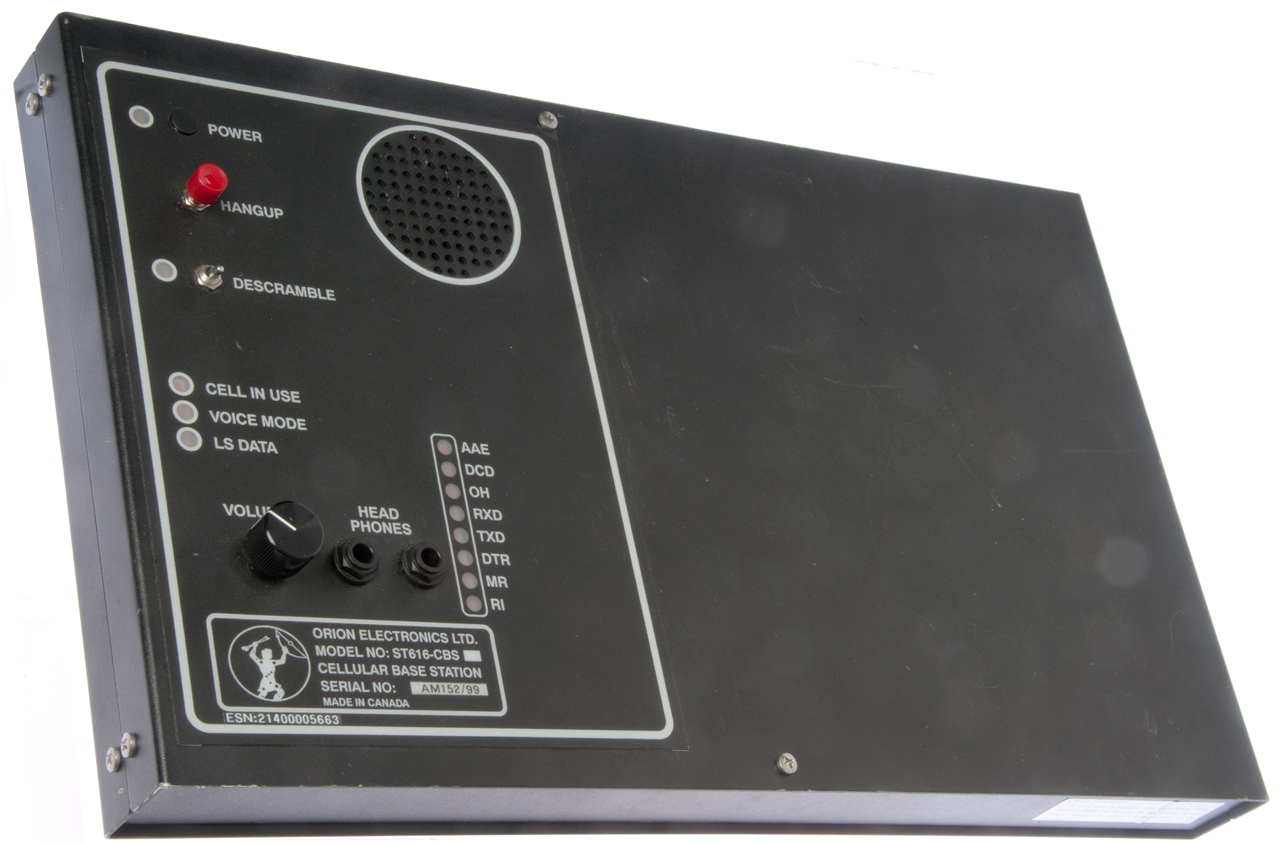
Fig 1 Top Control Panel
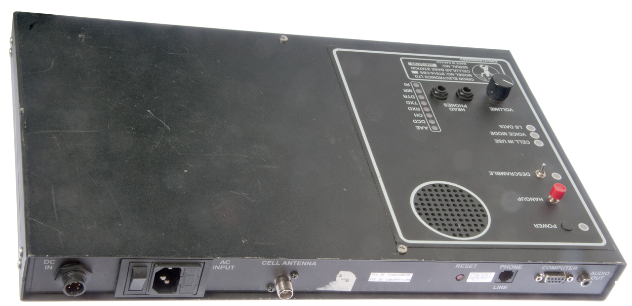
Fig 2 Back Connectors
Fig 3 Bottom Inside PS, RF Amp/Dip, Digital
Fig 4 Inside RF Amp - Diplexer
Daughter board on Digital Board has watch crystal
so probably some type of real time clock. Note provision
nearby for backup battery.
There are four main components: The digital board, the RF board, the RF power amplifier/diplexer and the AC power supply.
RF Amplifier & Diplexer Model PBK-800A (Fig 4)
There is a warning sticker:
"Safety Information
If your unit is equipped (spelling) with PK-800A, PBK-700A or PBK-550 Booster, do not operate the unit when someone is within 2 feet (0.6 meter) of the antenna."
I'm guessing that these correspond to 8, 7 and 5.5 Watts output power respectively.
The RF amplifier module is a Toshiba S-AU64, I have a request in to Toshiba, but haven't been able to find out it's frequency range or power out.
The diplexer has the left end (near the S-AU64) marked TX and the right end marked RX. It's p/n is EZFR836J881R.
The Wiki page for GSM frequency bands shows GSM-850 (Wiki) with:
GSM-850 uses 824–849 MHz to send information from the mobile station to the base station (uplink) and
869–894 MHz for the other direction (downlink). Channel numbers are 128 to 251.
Note: SQRT(824 * 849) = 836 and SQRT(869 * 894) = 881, these numbers appear in the diplexer model number.
So this is a GSM-850 box.
The RF antenna connector is a TNC-f.
Ordered an antenna on eBay: Magnet cellular 800Mhz 850 3dB colinear antenna with cable TNC.
It's an Antenna World CLR-877 Deluxe Magnetic Mini Cellular Antenna 3 dB Gain 824-880 MHz, 9 Ft. Cable, TNC-m connector Made in USA.
AC Power Supply (LCA50S-12) 12 Volts @ 4.3 Amps (Fig 3)
Since there's only a pair of wires (red & black) as outputs from the AC power supply and because there's an External DC input (1: ground, 5: +12 VDC) that the power supplies a nominal "12 Volts" and that the box will run on the range of 10 to 15 VDC, i.e common automotive DC power.
Digital Board & real time clock daughter board. (Fig 3)
Marked Orion ST-615 Rev 2, 9/13/99. There's a 52 pin socketed chip marked: ST616, Opt 0x05 that probably is a ROM or EEPROM.
There are a number of empty component pads so this board is not fully optioned. There's also an unpopulated location for a back-up battery (BT1).
RF Board
This is a 4.5" x 2" board located under the Digital board right next to the RF Amp/diplexer and is the actual cell base station electronics.
It has a single white coax cable going to the RF Amp/Diplexer that handles both transmit and receive using frequency division multiple access (Wiki: FDMA) rather than a T/R switch.
Front Panel Controls, Indicators & Connectors
Power LED
Hangup momentary button
Descramble On/Off switch and LED (Note: This implies GSM and the ability to break the crypto)
Cell in Use LED
Voice Move LED
LS Data LED
Volume control
2 each 1/4" headphone jacks
Modem Status LEDs:
Label
Meaning
AAE Auto Answer Back
DCD Data Carrier Detect
OH Off Hook
RXD Receive Data
TXD Transmit Data
DTR Data Terminal Ready
MR Modem Ready
RI Ring Indicator
Wiki: Hayes command set for GSM
Rear Panel Connectors (Fig 2)
Label
Function
DC In
Conxal?
12 VDC Input
(1: ground, 5: +12 VDC)
OAC Input & Switch
Std IEC line cord
Cell Antenna
850 MHz GSM TNC-f
Reset Button
Phone Line
RJ-11
Computer
DB-9F serial COM port
Audio Out
RCA Jack
If you have any information about how to operate this box, please let me know.
Although my Motorola Electrify cell phone can operate on the GSM 850 MHz band that's not how my cell carrier works, so when I make a phone call the box does not react.
There may be a way to use the box by means of the RS-232 COM port. But that probably requires some software or knowing the commands.
Cryptography
Crypto Machines
Crypto Patents
Spying on Cell Phones
Fastrak & License Plate Cameras
How Law Enforcement Tracks Cellular Phones by Matt Blaze
German researchers discover a flaw that could let anyone listen to your cell calls. - bugs in SS7 (Wiki) backbone switching system
Brooke's: PRC68, Alphanumeric Index of web pages, Products for Sale, Contact
Page created April 2014