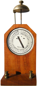
If you look closely all the letters and
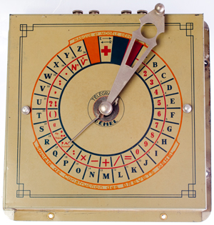
numbers are accompanied with their Morse Code equivalent. Also that the pointer's motion is restricted by two brads. The positions are to the left i.e. pointing to 7 or to the right pointing to D. When no current is flowing it should point up to the black space. This way when either positive or negative current is applied, not only will the pointer tell you if it's a dot or dash, but the bell will ring to indicate a new symbol. |
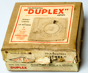
This is a French toy version of the toy
dial (ABC)
telegraph by Bénévolo (France). In that toy the pointer does point to the letter. This one could have been made to work, but you can tell it's just a 3 position version by the two brads to limit the pointer position. |
This appears to be a working dial
telegraph where the pointer moves to the desired letter.
The two terminals on the right in Fig
1 are the inputs to the receiver. The electromagnet just
pulls in at 96 ma and 0.922 Volts (9.6 Ohm coil).
The electromagnet just drops out at 8 ma and 0.088 Volts (11
Ohms).
The two terminals at the top left in
Fig 1 are the transmitter contacts. When at rest the
contacts are open and they close once for each incremental
movement of the transmit arm.
Black Wires: Shows the left dial
telegraph transmitter (left) terminals in series with the battery
and the receiver (right) terminals of the right dial telegraph
transmitter.
Red Wires: Shows the right dial telegraph transmitter (left)
terminals in series with the battery and the receiver (right)
terminals of the left dial telegraph transmitter.
This is a full duplex wiring where each person can send and
receive at the same time.
My bench power supply is the Agilent
(HP) E3617A which is capable of up to 60 volts at 1 Amp.
In order to get the highest loop resistance the supply should be
set to 60 Volts and to max current.
Using 100 ma loop current the drop across the electromagnet will
be about 0.1A * 10 Ohms = 1 Volt) so a series dropping resistor is
needed.
R = V/I = (60-1) / 0.1 = 590 Ohms.
The transmit terminals seem to be
completely isolated from the receive terminals.
The over voltage protect is tripping on the power supply, probably
due to voltage spikes from the electromagnet when the switch
opens.
This might be helped by placing a
resistor in parallel with the receive terminals that's on the
order of 100 Ohms. That way when the relay coil circuit
opens instead of generating a very large voltage it will only
generate the current (100 mA) times the 100 Ohms or 10 Volts.
Fig 1 |
Fig 2 |
Fig 3 |
Fig 4 |
1647
Telegraph
Signs,
S.F.B.
Morse,
Jun 20 1840, 178/2R ; 178/17R; 178/70A; 178/86;
178/89; 341/66 |
||
10292
Dial
Telegraph,
J.
Davis,
Dec
6 1853, 178/17R |
||
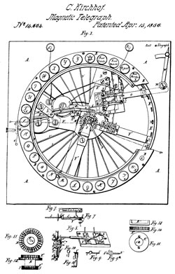
14664
Improvement
in
Electric
Telegraphs,
C.
Kirchhof, Apr 15, 1856, 178/17R ; 178/64 |
||
25718
Improved
Telegraphic
Machine,
L.
Bradley, Oct 11, 1859, 178/3 ; 178/17R Based on the Morse blocks,
not a dial telegraph in the classic sense
|
||
37997
Dial
Telegraph,
A.
Bain,
Mar 24 1863, 178/17R ; 341/67 |
||
39376
Dial
Telegraph,
G.W.
Beardslee,
Aug 4 1863, 178/17R ; 211/49.1 |
||
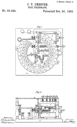
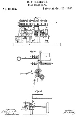
40324
Dial
Telegraph,
C.T.
Chester,
Oct
20, 1863, 178/17R |
||
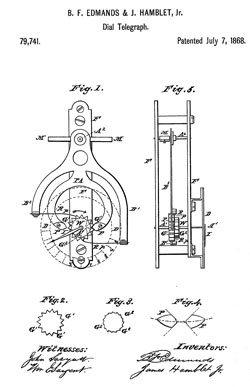
79741
Dial
Telegraph,
B.F.
Edmands
& J. Hamblet Jr, Jul 7 1868, 340/815.58 |
||
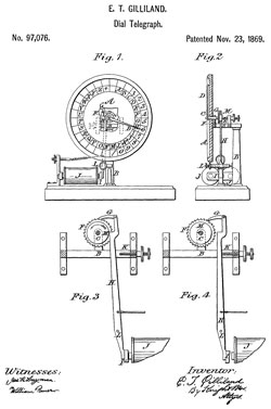
97076
Dial-Telegraph Apparatus, E.T. Gilliland, Nov 23 1869, 74/156
; 340/815.58; 340/815.78 |
||
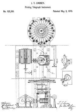
102561
Printing Telegraph Instrument, J.T. Lindsey, May 3, 1870,
178/35 |
||
112360
Telegraph Apparatus, L.T. Lindsey, Mar 7 1871, 178/42
; 340/319; 340/815.58 |
||
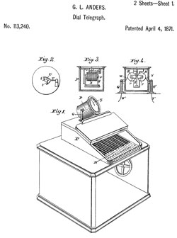
113240
Dial Telegraph, G.L. Anders, Apr 4, 1871, 178/17R |
||
114793
Printing Telegraph, T.M. Foote 7 C.A. Randall, May 16
1871, 178/38 ; 178/41 |
||
116429
Dial-Telegraph Apparatus, E.T. Gilliland (Hiram D.
Rogers), Jun 27 1871, 340/815.58 |
||
116430
Dial Telegraph, E.T. Gilliland, Jun 27, 1871, |
||
128708 Dial Telegraph, S. Chester, Jul 9 1872, 340/815.58 | ||
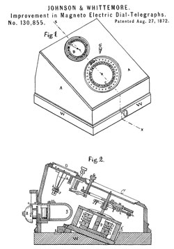
130855
Magneto Electric Dial-Telegraphs, J.B. Johnson &
H.Whittemore, Aug 27 1872, 178/18.07;341/35 |
||
139690 Printing and Dial Telegraphs and Circuits Therefor, H.D. Rogers, Jun 10 1873, 178/35 ; 178/109 | ||
148946 Printing-Telegraphs, M. Gally, Mar 24, 1874, 178/26.1 ; 178/28; 178/86 | ||
172219 Electric Circuit for Fire and Police-Telegraph, W.B. Watkins, Jan 11, 1876, 340/292 | ||
173750 Printing Telegraph, G.L. Anders, Feb 22, 1876, 178/35 | ||
179082 Dial Telegraph, H. Van Hoevenbergh, Jun 20, 1876, 340/815.78 | ||
181583 Dial Telegraph, J.C. Ludwig, Aug 29 1876, 178/17R | ||
186283 - Dial
Telegraph, Jan 16, 1877, 178/18.03
; 178/109 |
USPTO error 186282 Sample Garmets? | |
266987 Ship Telegraph, J.S. Gisborne, Nov 7 1882, 340/319 ; 40/469 | ||
320923 Individual Signaling Apparatus, E.F. Frost, Jun 30, 1885, 379/418; 310/69; 340/6.16; 340/401.1 | ||
414343 Tell Tale Apparatus for Ship Telegraphs, W.T.W. Thackeray 7 I. Hurn, Nov 5, 1889, 340/314; 116/21; 200/4; 200/52.00R | ||
436154 Electric Signal for Railroads, F.C. Schroen, Sep 9, 1890, 246/9; 191/49; 246/191 | ||
443111 Printing Telegraph, F.B. Rae, Dec 23, 1890, 178/64 | ||
463852 Synchronous Telegraph, C.S. Bradley, Issued Nov 24, 1891, 370/304 | ||
1144290 Telegraphy, B.L. Bobroff, Jun 22 1915, 340/319 | ||
1157839 Telegraphy, B.L. Bobroff, Oct 26 1915, 340/330 ; 123/146.5D |
1677062 Signaling system applicable to telegraphy and telemechanical transmission, Charles Verdan, Jean Loiseau Louis Marie, Jul 10, 1928
See Ruhmforff coil
http://shtukoviny.ru/pointer/info.html