HP 3458 DVM
© Brooke Clarke 2009Photo
Background
DOA
Options
Reading Calibration Memory
Patents
History
Test Leads
Voltage References
Links
Background
During my career as an engineer
I specified this meter into automatic test systems and wrote
code to control them. The key feature is that they are
very accurate. For example when the definition of the
Volt changed we had some instruments with a sticker saying
that they measured the new Volt. When comparing those
with the no sticker meters the difference was the difference
in the Volt definition. Quite impressive.
HP Journal for April 1989 - describes the new developments.
HP Journal for April 1989 - describes the new developments.
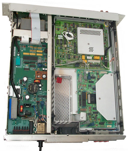
DOA
The manual does not have the
details necessary to troubleshoot down to the component
level. They use board level replacement to fix problems.
This one came from eBay and was
sold untested and marked "Strapped for 220 VAC". It's a
very simple thing (rear panel switches) to set it for 120
VAC. But on power up there is a single beep, the display
shows "testing RAM" and all the icons and pixels are on, then
quickly changes to ISOLATOR DTACK and locks up there.
Pressing Blue and or Error either at the same time or in
sequence does nothing. The error message is associated
with the A5 Outguard Controller board.
Pressing Blue then Clear or Blue + Clear has no effect on the error message.
Disconnecting and reconnecting all the electrical and FO joints had no effect.
There is a smell like hot phenolic but so far haven't found where it's coming from.
Pressing Blue then Clear or Blue + Clear has no effect on the error message.
Disconnecting and reconnecting all the electrical and FO joints had no effect.
There is a smell like hot phenolic but so far haven't found where it's coming from.
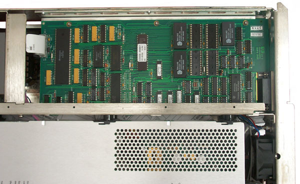
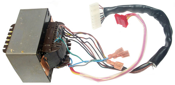
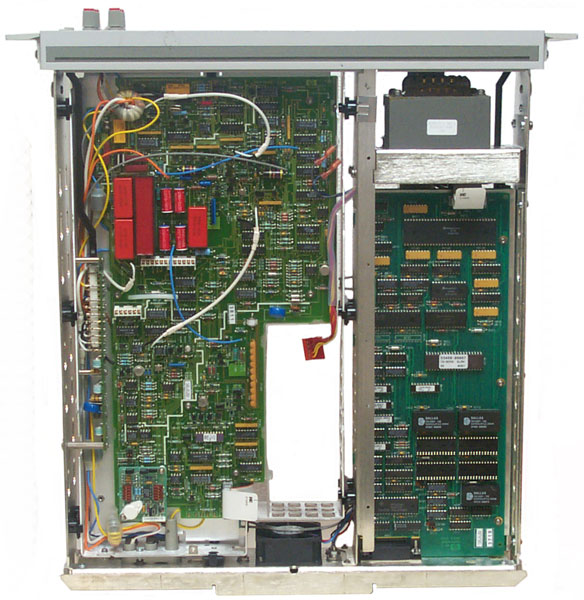
Options
My board is -3458-66505 Rev
C and is the non option 001 version. The option 1
board would be 03458-66515. Option 001 is extended
reading memory and probably consists of filling positions
U122, U123, U124, U125 with RAM chips and relocating JM600
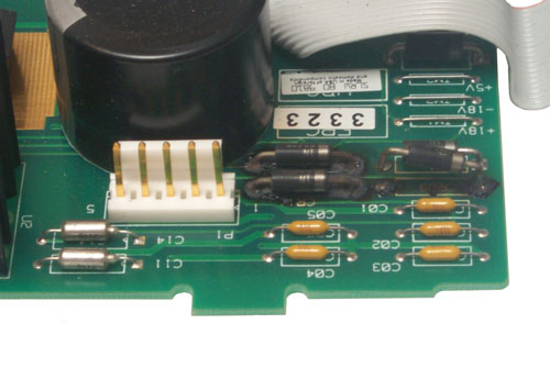
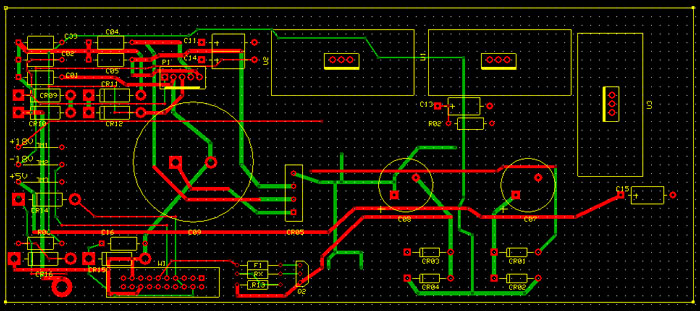
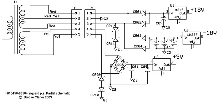
(just a guess, not yet analyzed). The Outguard Power
Supply board (under bottom cover) shows the two +5 VDC test
points to be right in the middle of their allowed range.
The +15 VDC test point (P3 red wire) reads 14.0 VDC but there
doesn't seem to be a spec for it.
Option 002 is marked on the rear panel label. That's the high stability Voltage reference (4 ppm/year).
I have on a bookshelf somewhere the Waveform Analysis Library (03458-80002). The 3458 can work like a sampling scope but the data comes out in a strange (interleaved) pattern and needs to be put back into time order in order to get a "scope" like display on your computer.
Reading Calibration Memory
There are some memory chips that have an internal backup battery and some instruments are getting old enough that the battery is going dead causing the loss of calibration data.
Thanks to the work of Poul-Henning Kamp there's a way to read out the data from these chips.
--------------------
All you have to do is enter the commands
	TRIG HOLD
	QFORMAT NUM
	MREAD 393216
	MREAD 393218
	MREAD 393220
	...
	MREAD 397308
	MREAD 397310

and save the results.

But that's 2048 MREAD commands, so having a program to do it
would be a lot easier...
------------------------------
and here is some sample data:  HP3458Sample.txt
Patents
These are patents that may be related to the HP 3458A.
4357600 Multislope converter and conversion technique, James Ressmeyer, Joe E. Marriott, Lawrence T. Jones (Hewlett Packard), Nov 2, 1982, 341/129
4766401 Coaxial switching system with switched shields and crosstalk suppression, David P. Kjosness, Joe E. Marriott (Hewlett Packard), Aug 23, 1988, 333/12; 333/262; 335/5
4951053 Method and apparatus for switching currents into the summing node of an Integrating Analog-Digital Converter, Lawrence A. DesJardin, Wayne C. Goeke (Hewlett Packard), Aug 21, 1990, 341/136; 341/135; 341/155; 341/172
5200752 Integrating analog to digital converter run-up method and system, Wayne C. Goeke (Hewlett Packard), Apr 6, 1993, 341/168; 341/166
5117227 Continuously integrating high-resolution analog-to-digital converter, Wayne C. Goeke (Hewlett Packard), May 26, 1992, 341/166; 341/156
5148171
5689260 Analog-to-digital converter using scaled signal to initialize coarse conversion circuit, David Gerard Vallancourt, Lucent Technologies Inc., Nov 18, 1997, 341/156, 341/158
History
This account provided by Dr. Frank and is
provided with his authorization. First appeared on the
Volts Nuts list server.
| I also picked one up, a
mixed one, ie old analogue PCB from the 90's and a
younger processor board from 2001 (perhaps replaced
due to SRAM battery discharge). Cost me about 3k
instead of of 8k new, and its working perfectly - but
stable environmental temperature conditions are
required, that's the weak point of the design. Maybe its an old design, but currently, no other DMM or calibrator can beat it essentially in certain parameters. It has got the best (differential) linearity, over Keithley 2002, Fluke 8508A, Datron 1281, Fluke 57xx and even the Primary Ratio standard 720A! Only the JJ array can test its linearity! OK, the 3458A's internal references are not that stable, but it is not intended as a secondary volt or ohm standard. For that you need additionally something like a 732B and a SR 104, or the quantum standards, respectively. But all others of the above mentioned, newer DMMs are not much better. For DCV, the 3458A obviously has been designed for a very broad temperature range of 0..55°C (military use??), which gives an internal temp of at least up to 80°C in a rack mount. Placing its internal volt and ohm standards in a lower and more stable environment would have been better, but then, it could not have been a DMM-in-one-box. So the internal LTZ1000A reference has to be running on 90°C. If powered constantly, this gives at least 20 times higher drift rates over time compared to a Fluke 7000A, which is running on 45°C. Other DMM are specified for meteorological temp. range and have certainly slightly better drift rates (two times). I have set (pimped) the LTZ to about 55°C for lower drift. The HV divider cannot be corrected for power dissipation effects, so the 1000V range is quite mediocre. I have built my own 100:1 Hammond type divider (~ 752A) to get around 1ppm for 1000V. The ohm ranges obviously is its weakest mode. It relies on an elder hermetically sealed Vishay resistor, with high time and temp. drift, and additionally the resistor is exposed to the strong internal temperature variations. Today, by using a selected VHP202Z resistor, one might improve time drift to <1ppm/year and stability (with respect to temperature) to < 0.2ppm over the complete "meteorological" ambient temp range. Additionally, its ohms range resistors are very sensitive to temperature changes. But it is possible by using it in absolutely stable amb. temp. conditions (+/- 0.2K), to make 10k Ohm measurements / transfers on sub ppm stability level. Currently, I'm working on external 10k standard resistors; but still in discussion with Vishay. Report will follow. ACV is also unparalleled by other DMMs, due to its (patented?) digitizing algorithms, and this can be further improved by Swerleins Algorithm. So I think, only Flukes AC standard 792A is "better", if using standard electronics. So my advice, get one used 3458A, it's simply a nice and ultra precise box, and build yourself some standards which you would need also if you got a newer DMM. Btw.: A good, absolute calibration is nearly impossible to acquire for us amateurs. Even Fluke and Agilent obviously offer 2nd grade calibrations only. Frank |
Test Leads
Ready made: Fluke 5440A-7003
DIY:
Belden 8719 2-pair shielded cable
blue Pomona patch cables (B-18-6)?
Gold over Copper low thermal lugs: JW Solutions or Pomona 2305 Low EMF lugs
Voltage References
The Linear Technology LTZ1000 is the heart of many voltage references see LT app note 86 appendix I Fig 12.
LTZ1000 chips: eBay seller polida 2088
2019 October 23 eBay "Precision Voltage Reference" sorted highest price first, only reporting modules, not raw parts, not complete instruments.
Basis
Volts
$
Accuracy
LT1021 10
97
0.003% AD584
2.5, 5, 7.5, 10
88
LM399AH
10
56
AD588
5, 10
57
LM399
2.5, 5, 7.5, 10 38
LTC6655
3.3/5
22
Links
K04BB - HP 3458A Precision Digital Multimeter - two different HP calibration options
Volt Nuts mailing list
HP/Agilent mailing list
Back to Brooke's Products for Sale, Test Equipment, Microwave Test equipment, Military Information, Home page
[an error occurred while processing this directive] page created 28 July 2009.