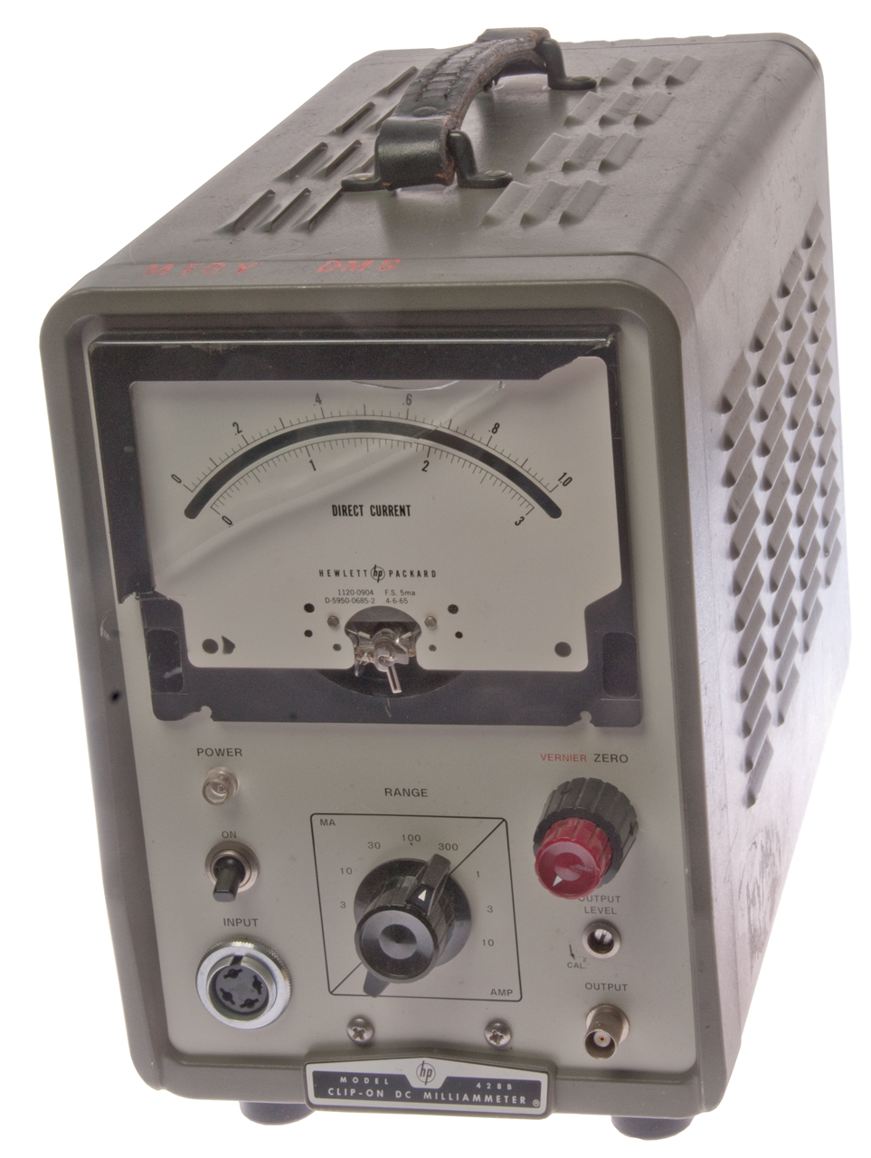
HP 428 Clip-on Milliammeter Magnetometer
© Brooke Clarke 2016 - 2022
Description
Meter
Test Points
Repair First 0995
Repair Second 0995
Karin's Probe Repair
Probes
KS-20199
Probe Electrical Check
Probe/Magnetometer Drive
Tubes
Photos
Patents
HP Journal
Manual
Clone
Related
References
Links
Background
One of my areas of interest relates to magnetism. And in particular the Earth's magnetic field. There many sensors that work with AC magnetic fields and others that work with DC magnetic fields. Of the DC field sensors only some work with fields as weak as the Earth's. One type of DC sensor good enough for Earth's field work is the Magnetometer and the HP 428 is a magnetometer processor and the probe is a magnetometer designed so it's core can be opened (clip-on).
Years ago I used a current transformer mounted in the electrical panel on the main feed hot wire to monitor the electrical usage for the whole house. There ware clamp-on current transformers, but they had a much smaller dynamic range than the solid core type. This may apply to clip-on probes vs. a probe made from a solid core where the wire needs to be threaded through it?
I've known about the 428 for some time but had not realized that it was a magnetometer at heart. Flux gate is a type of magnetometer and is what's used in the 428. See my Flux gate patents web page for more on those.
Most fluxgate magnetometers use the second harmonic method of detection and the 428 does this with a fundamental frequency of 20 kHz with the second harmonic of 40 kHz. So it could be used with any fluxgate that works at those frequencies (assuming the drive is adequate).
If the jaws of the stock probe are opened the Earth's field might show up as a current of up to 500 mA.
Paragraph 5-23 Noise Check says to point the probe East-West, which would have the red polarity arrow pointing North South and rotate the probe. On the 1 mA range the reading should not change more than 0.1 mA. If there are particles keeping the probe jaws slightly open the Earth's magnetic field will be sensed. Want to try this with something holding the jaws slightly open, like paper or 3x5 card stock.
Description
The HP 428 uses a 20 kHz drive to the flux gate and senses the 40 kHz second harmonic. The output of the synchronous detector is converted into a DC signal that's fed back to the flux gate in order to cancel the magnetic flux generated by the current carrying wire, so it's a null type detector. The feedback DC current is also used to drive the front panel meter. The calibration procedure matches the sensitivity of the flux gate to the calibration of the front panel meter.
Meter
There are different versions of the 428 magnetometer.
Model
Description
428A
Vacuum tube point-to-point wiring 428B (s/n <= 994)
Vacuum tube point-to-point wiring
Uses 2ea 6AL5 dual diode tubes
to form a 4-leg sync det.
428B (s/n >=995)
Vacuum tube & Transistor PCB
uses 4ea Ge diodes for sync det.
428C
Applied Physics
All solid state lab bench box
HP probe connector
428D - Data_sheet.pdf
Applied Physics
All solid state lab bench box
HP probe connector
428P - data sheet.pdf
Applied Physics
All solid state hand held,
small probe connector
428DIY
Do-It-Yourself Version
The 428 s/n 0995 was sold on eBay and fails to power up. A quick DMM checks shows that the On/Off switch does not reliably turn on.
The similar toggle switch on the back panel also has a problem. You can get it to open in the On position by pressing left or right.
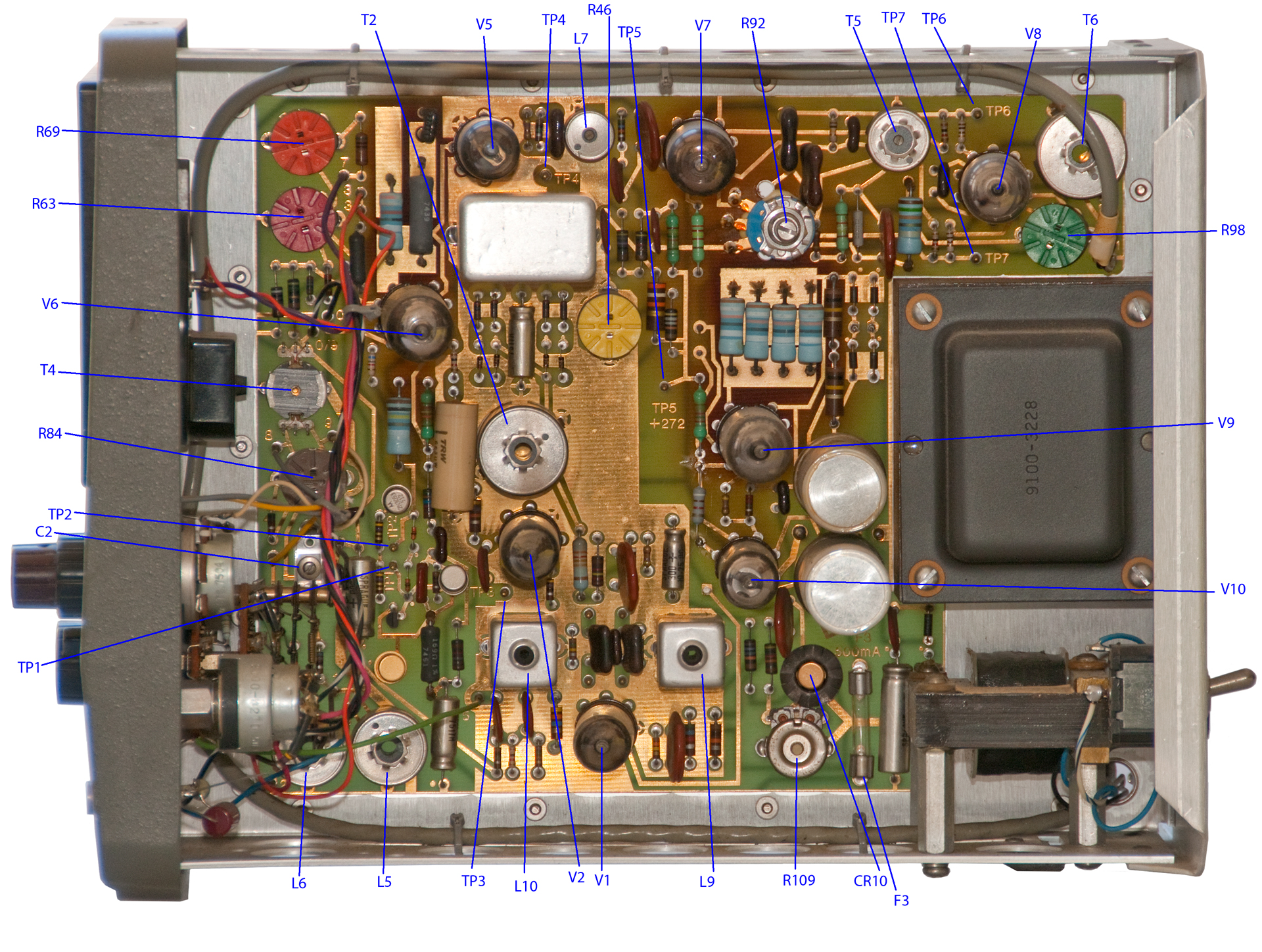
Test Points
TP
Description
Target
0995
Measured
Adjust
1
Metering Q2 base
2
Metering Q1 base
3
40 kHz Det cathode
C2 & L9 (peak)
R84 & R98 (min)
4
40 kHz Det Gate cathode
40 kHz +/- 200 Hz
T5, L7
5
Pwr Sup +272 VDC
272 +/- 6 VDC
R109
Pwr Sup CR10 cathode
+12 +/- 1 VDC
Pwr Sup CR9 anode
-7 +/- 1 VDC
6
20 kHz Osc right grid
8 +/- 0.4 VAC
R92
7
20 kHz Osc left grid
waveform
J1-2
20 kHz probe drive
waveform
Repair First 0995
Need a couple of toggle switches:
On-Off toggle switch (S2 p/n: 3101-0001) - does not turn on
momentary degaussing toggle switch (S3 p/n: 3101-0018) - You can tell by the hum when the switch is working correctly so don't need to replace it.
With a jumper on the power switch it powers up and the meter reads. Shows 1.80 A when current is more like 2.0 Amps.
TP5: the voltage climbs slowly after power on to very close to 272.
TP6 & TP7 both show 8.11 VACThe meter reads low maybe 10%. Need to figure out which adjustments are for calibrating the probe and which are general operation.
Repair Second 0995
The meter movement is destroyed. It's a 5uAmA full scale movement. about 30 mV full scale so a meter resistance of 6 Ohms.
Manual paragraph 4-43 says 5 mA maximum meter current.
Fig 7-10 metering schematic shows 5 mA next to the meter.
Using the Diode Test function on the Fluke 87 DMM causes the meter to read 0.18 on the 0 to 1 scale. So it's a 5 mA meter movement. It has about 6 Ohms measured internal resistance.
The meter circuit includes a 56 Ohm series resistor and 30 Ohm full scale adjustment pot so a 0 - 200 mV panel meter should work as a replacement and have the benefit of bipolar indication.
200 mV / 5 mA = 40 Ohms. May require changing the series resistor to center the full scale pot.
Checked the front panel BNC output and it seems to be -1 to +1 volt for the chosen scale. It works even with the ASW magnetometer (that has DC open terminals so no feedback).
But the First 0995 meter output seems to be zero all the time with a probe or the magnetometer, so it's got a problem.
But then only the 1, 10, 100 mA, 1 & 10 Amp ranges will read correctly without further modifications?
Karin's Probe Repair
I was trying to do an alignment of the instrument, and the 40 kHz signal would not null according to the test procedure. Also on the 10 amp range the meter would peg with no current through the probe. The instrument sort of worked intermittently. I don’t remember exactly why I suspected the probe, but it is always good to start with basics and test from scratch.
I googled your website and found the document on probe measurements. After seeing the correct ohm meter readings for the probe, I did confirm that there was an intermittent in the probe wiring. Also the connector on the instrument had loose pins so that was fixed too. After confirming the intermittent probe wiring, I took a sewing needle with my ohm meter and gingerly probed along the individual wiring after completely disassembling the probe head. I had to take off the protective resin coating very carefully, then unsoldered the wires to separate the four probe coils. I then used the sewing needle technique and found the broken wire near where it enters the coil. Luckily I had about ½ inch of good wiring so I could cut the bad section out then used some new wiring to re-assemble the probe. I put Capton tape back on the probe connections because there is a spring inside the probe body, to allow for the jaws to open and close.
Repair done.
Karin
The repair was to solder the broken brown wire just behind the probe jaws. Photos courtesy of Karin & background erased by Brooke.
Fig 1 Note tie wrap pointing down, let's call this the top side, no problem seen.
Fig 2 Note tie wrap pointing up, lets' call this the bottom side, broken brown wire seen and repaired.
Probes
The probes are serial number matched to the magnetometer. The s/n is scratched on the connector and is not visible when mated. The numbers are the last 4 digits of the instrument s/n.
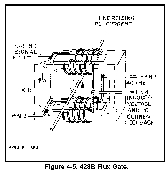
The probe is a flux gate magnetometer (see Flux Gate patents) where the drive causes the core to alternately saturate (magnetically like air) and return to a high mu condition at the drive frequency.
The drive and sense coils are arranged to minimize the direct coupling of drive to sense, but more important the sense is done at the 2nd harmonic of the drive so direct coupling is cancelled.
I did not see a prohibition saying not to change probes when the instrument is powered on, but if the instrument needs to be calibrated with a specific probe then that normally would not be done.
Connector
The probe connector is a standard microphone connector. Available on eBay either the male, female or a pair (M&F)
PC = Probe Connector? MC = Microphone Connector? Difference may be cable strain relief?
The 4-pin male connector on the probe is HP p/n 1251-0090, Mfg: 02660 (Amphenol) , p/n 91-PC4M (is the 91MC4M interchangeable?)
The 4-pin female front panel connector J1 HP p/n 1250-0089, Mfg: 02660 (Amphenol) , p/n 91-PC4F
Signals
Pins 1 & 2 are the 20 kHz drive & pins 3 & 4 are the 2nd harmonic output
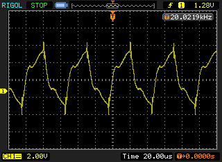
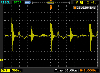
Below waveform captured while clamp was on wire carrying 1.00 Amps.
Rigol DS1052E scope.
Probe 20 kHz (50 uS) drive Pin 1
Probe 40 kHz (25 uS) output Pin 3
Note the drive waveform is may be slightly positive (would expect balanced or zero average), but the output waveform is 1.5V positive for DC, since the probe is seeing 1.00 Amps DC the offset may represent the feedback that the meter displays.
How to interpret the "1" at the left side of the grid. It's the position of 0 volts. When the "1" is positioned at the center of the grid on the pin 3 (output) with the probe one way the trace is above center (meter reads u p scale) and when the probe arrow is reversed the trace is below center (meter pinned to the left, down scale).
The 20 kHz, 8V pk-pk drive is between pins 1 & 2.
The 40 kHz output is between pins 3 & 4.
You can think of the probe as a bridge made up of inductors.
The top (pin 1) and bottom (pin 2) terminals are the drive.
The left (pin 4) and right (pin 3) terminals are the output.
428-21A Stock probe (p/n: 00428-62101)
After placing a clip-lead across on mains/n 0995 On-Off switch and installing probe 1 it appears to be working, i.e. with the jaws open moving the probe results in full scale swings.
3528A 2-1/2" Aperture probe
3529A Magnetometer (1 Gauss = 1 mA)
C11-3529A Magnetometer (1 Gauss = 1 mA) (HP Journal March-April 1963)
Magnetic Ink Testing for checks (HP Journal Nov-Dec 1961)
The first name on the patent for the 428 worked at Sperry Rand on a transducer for reading the magnetic ink on checks. Then he went to work for HP on the 428 meter. HP came out with a special probe for reading MICR on checks and a photo is in the 1961 HP Journal article.
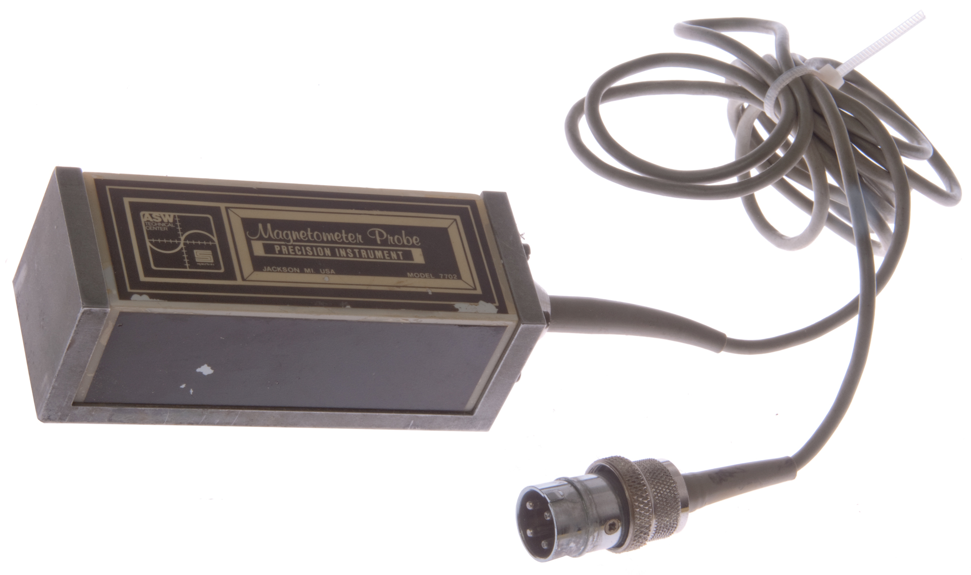
Model 7702 (Fig 6)
Made by ASW Technology Center, Jackson, MI
Marked: Magnetometer Probe, Precision Instrument
ASW: Anti Submarine Warfare.
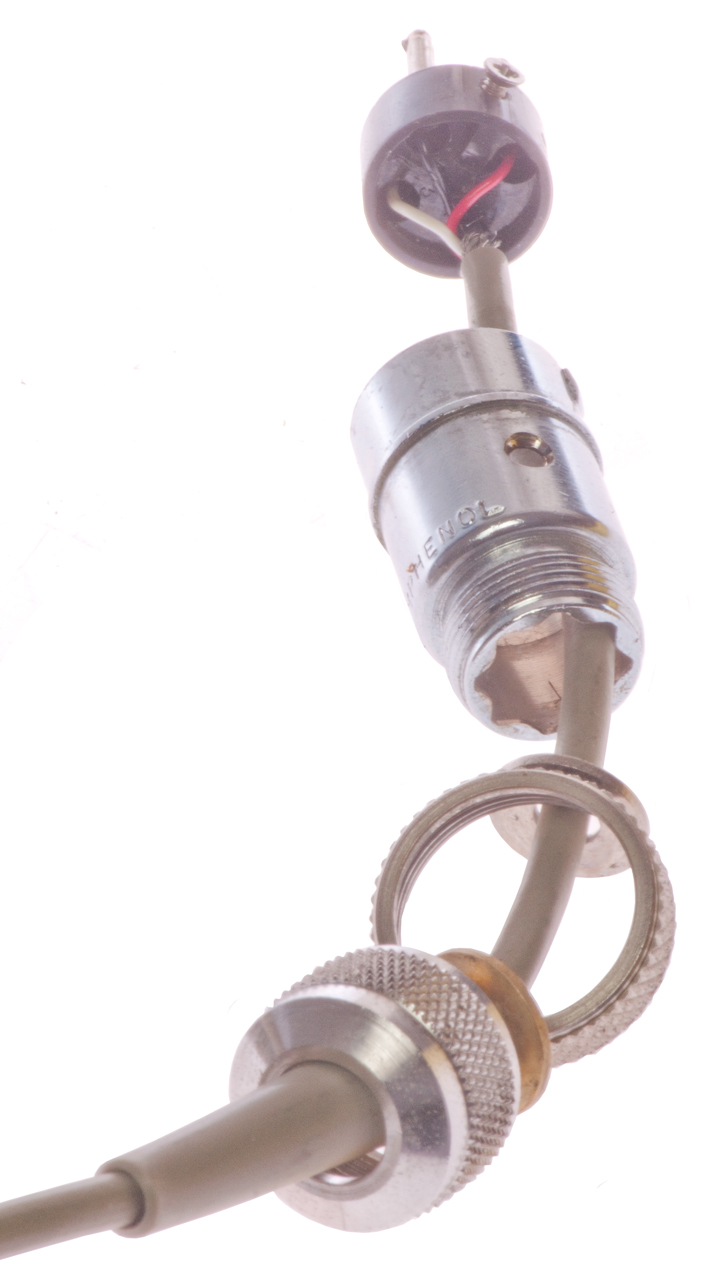
This probe came attached to the HP 428 with s/n starting 0995. But it tests open on all terminals. Opened the Amphenol connector and all wires look OK, so the reason for the open circuit is it's designed that way (capacitors on each terminal). Another possible explanation is that the probe was destroyed in shipping (see 0995 Fig 1 below) because the probe was loose in the box and banging against the meter front panel. It was not bubble wrapped.
The probe seems to be made up of a machined aluminum "U" with a plastic block inside the "U". 4-3/8" long x 1-5/8 square.
After placing a clip-lead across on main On-Off switch and installing this probe, it does respond to movement on most ranges, so appears to be working.
Note that since all the terminals are DC blocked, the DC feedback signal from the 428 does not effect the model 7702, but it does show on the front panel meter. I expect the meter was not used, but rather the DC output.
KS-20199 probe
September 2017 - there are a number of these on eBay coming out of China, but do not know what it is.
Label on wood box: "KS-20199 Magnetometer Probe,Made for Western Electric by Hewlett Packard."
KS numbers indicate a custom build. Let me know.
Probe Electrical Check
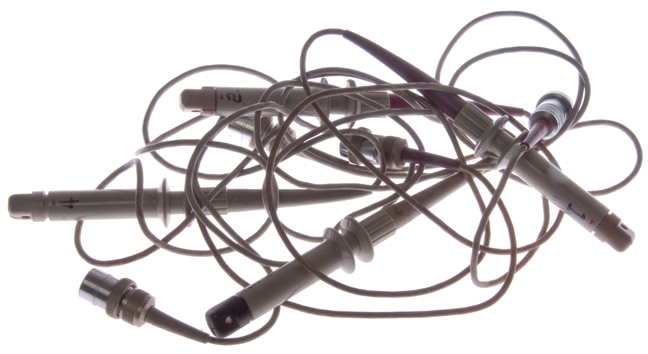
I've had an interest in the 428 meter for some time but have read that a large number of meters come without probes and the meters that come with a probe may or may not work. Those meters that come with a working probe are expensive. So when I saw a bunch of 428 probes on eBay that were advertised as something else I got them on a gamble. That's what started this web page. 3 out of 4 probes seem to be functional.
The manual uses a DC resistance measurement between: 1&3, 1&4, 2&3, 2&4 to check the probe. When testing capacitance on diode bridges I called this an "adjacent" measurement.
In this case it's the resistance of the inductor directly between the tested terminals plus a parallel inductor made up of the other 3 inductors.
A more sophisticated test would be to use an LCR meter, like the HP 4274 or 4275, to make a "guarded" "adjacent" measurement of inductance where one or both of the unused terminals was connected to guard. That way you could measure the resistance and inductance of just one of the inductors.
PS The alternate to an adjacent measurement is the diagonal measurement (1-2 or 3-4 in this case). In each case you are measuring the series connection of two inductors in parallel with the series connection of the other two inductors. Not a good choice if there is any possibility of partial guarding. A guarded diagonal measurement returns an reading of zero, i.e. no information. A partially guarded measurement is likely to have a large error.
Test Results of DC adjacent resistance measurement
* Black probe tip
Pins
Probe 1
Probe 2
Probe 3*
Probe 4
Model
7702
1-3
4.4
4.1
3.7
4.4
open
1-4
4.3
4.0
3.6
4.2
open
2-3
4.5
4.2
3.6
4.3
open
2-4
4.2
4.0
0.3
4.2
open
Probe 3 can be set to zero and seems to work, although it reads a little low as do all the probes.
Probe/ Magnetometer Drive
The drive signal is 20 kHz at 8 Volts peak to peak applied to pins 1 & 2.
If the resistance between pins 1 and 2 is around 4 Ohms then the drive current is around (8V / 4 Ohms) 2 Amps peak to peak.
This is important to determine the Amp-Turns for the Tape Wound Core, which needs to be 64 Amp Turns.
Tubes
428A
428B
p/n
Function
V1
6AH6
40 kHz Amp
V2
6AH6
40 kHz Detector Driver
V3, V4 na
6AL5
Sync det (A ver only)
V5
6AH6
Detector
If Gate Amp
V6
6DJ8
40 kHz Diff Amp
V7
6DJ8
20 kHz Osc
V8
12AU7
Probe Driver
V9
12B4A
Power Supply Series Regulator +272 Volts V10
6AU6
Power Supply Voltage Reference Amplifier V11
na
5651
Voltage Regulator (A version only)
I have most of these on order just in case.

Photos
Fig 1 Pile of HP 428-21A Current Probes
First 428B s/n prefix 0995
0995Fig 1 Nothing says Bad Packing like a FRAGILE sticker.
I could feel something loose as soon as I picked up the box.
The box was squishy, i.e. not fully filled.
Fig 2 Front
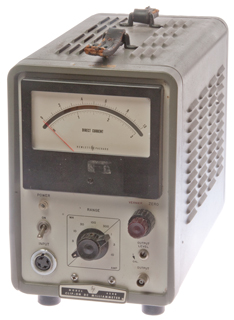
Fig 3 Back
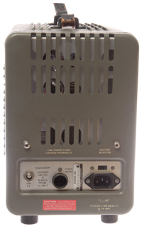
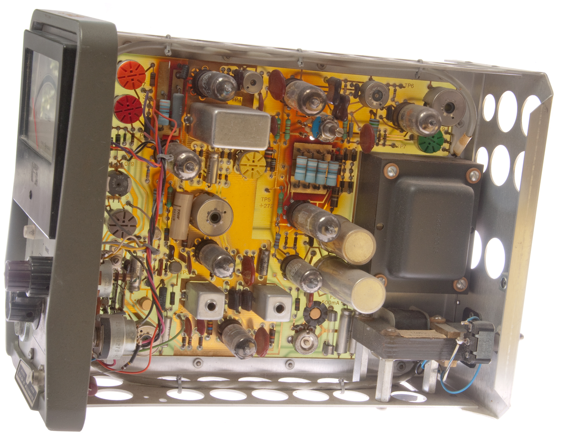
Fig 4 Left Inside - bottom of PCB
Fig 5 Right Inside - top of PCB
Fig 6 ASW Technical Center, Jackson, Mi, USA
Magnetometer Probe, Precision Instrument, Model 7702
Fig 7 Model 7702 connector wiring
Pin
Wire
1
Red
2
Black
3
White
4
Shield
Fig 8 Test Points & Major Component Locations
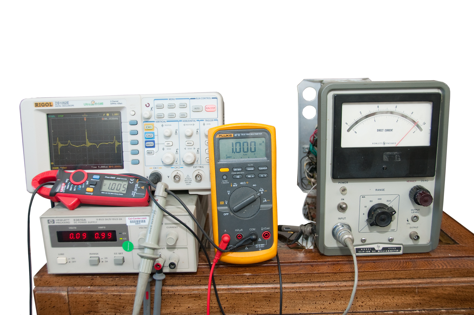
Fig 9 A clip-on meter with DC current capability
Note: the jaws have a lot of room for looping wire.
Easy to get 10 turns of test lead wire, but reading 10 A
requires changing range and that causes the loss of a decimal place.
So the best accuracy is when reading near full scale.
Fig 10 Scope: trace is 2 squares (1.5 V) above zero
HP E3610A: 0.09 v, 0.99 ADC
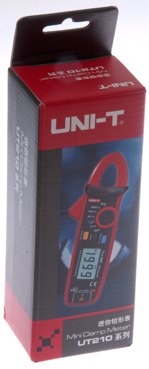
Uni-T UT210E: 1.005 ADC
Fluke 87V: 1.000 ADC
HP 428: 0.92 ADC


Second HP 428 (serial prefix 0995)
Fig 1 Excellent condition except the meter was destroyed.
Carry handle in tact.
Fig 2 PCB shows minimal heat browning
Fig 3 Pristine internal condition.
The meter is a o to 5 uAmA movement and has about 30 mV full scale
Rmeter = 6kOhms
The Output connector has a -1 to +1 VDC output.


Patents
2517975 Magnetometer probe, Daryl M Chapin, Bell Labs, 1950-08-08, 324/257; 102/417; 310/328; 310/318; 310/331; 367/161 - for point measurements (1/10 sq mm). piezo plate (Quartz crystal) vibrates and is conductive, so when in a magnetic field a voltage will be generated which can be measured.
It looks like Arndt B. Bergh was working on magnetic sensors to read MICR (Wik) on checks at Sperry Rand and then moved to HP and was part of the team that developed the 428.
2892041 Magnetic transducing apparatus, Bergh Arndt B, Oberg Paul E, Rubens Sidney M, Sperry Rand Corp, Filed: Oct 11, 1954, Pub: Jun 23, 1959 - for reading MICR on checks - Vo independent of speed of check movement.
2994428 Sorting apparatus, NCR, Aug 1, 1961, 209/564, 209/567 - for sorting bank checks using MICR
Smartcheque: MICR waveforms - Overview - the magnetic signature can be read even ordinary ink, like from a signature or stamp, is on top of it.
3007106 Current meter and probe therefor, Bergh Arndt B, Kan George S, Hewlett Packard Co, Oct 31, 1961, 324/127, 324/117.00R, 323/358, 336/215, 336/175 - for HP 428 meter.
Calls:3280974 Method and apparatus for recognizing printed currency, Bergh Arndt B, Forge Charles O, Riddle John B, Filed: Aug 23, 1961, Pub: Oct 25, 1966 - Magnetic ink character recognition (Wiki: developed in the late 1950s)
2632883 Magnetometer system, Richardson Max S, Mar 24, 1953, 324/253, 323/363 - half bridge
Calls:
2560132 Unbalanced magnetometer, Schmitt Otto H, Jul 10, 1951, 324/255, 340/870.33 - aimed at magnetic anomaly detection
Calls:
2252059 Method and a device for determining the magnitudes of magnetic fields, Gustav Barth, filed: Dec 24, 1936, pub: Aug 12, 1941, 324/253, 102/427, 102/417, 340/870.33, 33/361 - maybe THE original Flux Gate patent? 43 other patents reference this one.
No calls to prior art. Don't think the idea of the second harmonic is in this patent.
2468968 Magnetic field strength indicator, Felch Jr Edwin P, Thaddeus Slonczewski, Bell Labs, Filed: Apr 20, 1943, Pub:May 3, 1949, 324/246, 340/870.33, 324/253, 324/345 - adds 2nd harmonic
2477337 Magnetic detector, Kahl William E, Bell Labs,Filed: Jul 31, 1944, Pub: Jul 26, 1949, 324/253, 324/254 - adds 2nd harmonic
In the HP Journal Nov-Dec 1961 issue it shows an optional probe for testing MICR on checks.
4914381 Direct-coupled fluxgate current sensor, Barry Narod, Barrigar & Oyen, Apr 3, 1990, 324/117.00R, 324/253, 336/214 - 0.5 uA sensitivity - Characteristics of the capacitively loaded flux gate sensor - behind paywall, but has summary indicating many orders of magnitude improvement and stability issues.
HP Journal
HP Journal June-July 1958 - A Clip-On DC Milliammeter For Measuring Tube And Transistor Circuit Currents - pre release article
HP Journal May-June 1959 - A Clip -On Oscilloscope Probe for Measuring and Viewing Current Waveforms - Model 154A Amplifier & AC-21F Clip-on Probe
HP Journal Nov-Dec 1961 - Broader Information Capabilities in the Clip-On DC Milliammeter Magnetic Ink Testing on checks & large-aperture probe
HP Journal March-April 1963 - page 7 - 3925A Sensitive probe (1 gauss per Amp)
Manual
428B
00428-90002 Oct 1966 (pdf) - serials prefixed: 131-, 601-
428B
00428-90003 Nov 1970 (pdf) - serials prefixed: 995- and above - enhanced with color coded probe exploded view (pdf page 35)
also see HP Agilent Serial Number Date decoding.
Clone
It would be handy to have a reasonably priced solid state clone of the 428. (the Applied Physics units sell used for almost $1k).
A simple way to do that may be using the TI DRV401. It requires an external fluxgate, unlike the DRV421 that has a built-in flux gate so can not be used with a stock HP probe. The potential problem is that the operating frequency of the DRV4-1 is over 10X higher than the HP probe was designed for.
Related
3 Axis Magnetometer
Aircraft Pilot's Standby Magnetic Compass
DC Gaussmeter Model 1
AMY6 Magnetic Polarity Tester
GE Gauss Meter & Reference Magnet
DC Permanent Magnet Motors
Experiment Relating to the Vertical Component of the Earth's Field using digital wrist compass
Electromagnet Toy Engine
Fluxgate (& other) Patents
Helmholtz Coil
Sensitive Research Instrument Co. Fluxmeter
Annis M25 Pocket Magnetometer
Cenco Scientific 79860 Dynamo Analysis Apparatus - works with Fluxmeter
Home Built Magnetometers
HT20 2000 mT Magnetic Flux Meter- DC but not sensitive to Earth's field
KVH C100 Flux Gate Compass module
Magnetic Locators
Magnetics
Magnets Permanent magents & electromagnets
MC1 MC-1 Magnetic Compass Calibration Set similar to AN/ASM-344
Sensors - Magnetic
Sonobuoy - CRT-1B sonobuoy - CRT-3 Gibson Girl life boat rescue transmitter
Weeden-El-Mtr Weeden DC Electromagnetic Machine (Motor or Generator) & Carbide (acetylene) Gas Cannon
References
DIYaudio - Modernized HP428 clone - information on a modern implementation of the 428.
HP Journal Vol 9, No 10-11 June - July 1958 - A Clip-On DC Milliammeter for Measuring Tube and Transistor Circuit Currents - 428A
"In order to make the instrument suitable for measuring small currents, considerable care has been taken to minimize the effects of external fields on the probe elements. The effect of external homogeneous fields is minimized by a balanced arrangement for the probe elements. In practice, the chief homogeneous field to be dealt with is the earth's field, but it is interesting to note that from the standpoint of small-current measurement the earth's field is relatively very strong. Oneway of illustrating this point is to note that the earth's field is roughly the same as the magnetizing force produced in the probe magnetic circuit by a conductor carrying 1 ampere."HP Journal Vol 13, No. 3-4 Nov. - Dec. 1961 - Broader Information Capabilities in the Clip-On DC Milliammeter & side bar article "Magnetic Ink Testing"
HP Journal Vol 14 No. 7-8. Mar - Apr 1963 - A Conveient Probe for Sensing Magnetic Fields 3529A Magnetometer Probe 1 milligauss/milliampere (1 gauss/amp),
range 0.1 mg to 10g. (Earth's filed is about 500 mg) 0.26" dia x 1" long tip.
HP Memory Project - Animated inside view of 428B -
American Radio History - Electronics World, Vol 72, No. 3, Sep 1964, pg 41 - 43 & 88
YouTube - 160511 Value Studio - HP428 Clip-On DC Milliammeter - showing a 428B and 428A
Links
Applied Physics - makes the 428C, D & P as well as new probes.
PRC68, Alphanumeric Index of Web pages, Contact, Products for Sale
Page Created 25 July 2016