Helmholtz Coil
&
Fluxmeter
© Brooke Clarke 2015 - 2022
Background
Description
Construction
Photos
Electrical Parameters
Applications
Other related Coils
Making Coil Forms, Bobbins
Human Head
Ruska Helmholtz Coil
M3 Coil Magnetic Survey Instrument
Waugh MW3 & MW4 Magnetometers
Patents
Fluxmeter
Description
Integrating Op Amp Fluxmeter
W.W. II Fluxmeters
TS-15 Fluxmeter
Sensitive Research Instrument Co. Fluxmeter
Description
Operation
Documentation
H.C. For Fluxmeter
Annis M25 Pocket Magnetometer
Cenco Scientific 79860 Dynamo Analysis Apparatus
Related
References
Links
Helmholtz Coil
Background
I've known about uning Helmholtz Coils (Wiki) to generate a magnetic field, like for doing work with a magnetic compass. These are weak magnetic fields (The Earth's magnetic field is about 50,000 nano Tesla or 0.5 Gauss). Note at the diameter of the coil gets larger the field gets weaker. More current increases the field strength.
I recently got a DC Gaussmeter that has ranges of +/- 19,999 G and +/- 1,999.1 G. So on the sensitive range the Earth's filed is +0.5 to -0.5 G depending on the orientation of the probe. Placing the probe on the end of a strong permanent magnet overloads the meter. The question then is how do you measure the strength of powerful permanent magnets. The answer is to use a Fluxmeter and they are typically used with a Helmholtz coil.
Description
A Helmholtz coil has a uniform magnetic filed when driven by a current. The filed is uniform in a cylinder that's about 1/3 of the diameter of the coils and is between the end faces of the coils, so for this 12" diameter coil where the coils are spaced 6" the uniform volume is about 4" diameter and 6" long.
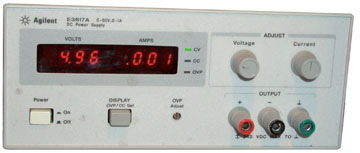
After rotating this coil so that it's centerline is East-West and then placing the DC Gaussmeter flat against the inside of a disk with the power supply at about 1 Amp the meter reads +1.3 Gauss and -1.0 Gauss when the polarity of the power supply is reversed. This is as expected since the design was for the Agilent E3617A lab bench power supply that has about 1 Amp maximum current. The number of turns was chosen for to be close to 1 Gauss at 1 Amp.
Construction
The hardware store has plywood disks in stock the smallest diameter being a nominal 12". Got a four foot long 2x4 from the inside wood and selected it for no knots, no splits and the lightest weight (some of them were more than twice as heavy). Used a single use miter box and saw ($5 total) to cut blocks so that the center of the plywood would be six inches apart. A paper template was made to locate the 2x4 blocks so that the edge of the circles would be up off the table to protect the wire. Two blocks were used rather than a much larger block for stability.
No. 32 AWG wire was chosen because it can carry the 1 Amp output of my HP E3617A power supply.
PS The first paper design was using clear acrylic plastic, but the parts cost would be over $50 and require a router and an assembly fixture. The wood design is much easier and lower in cost.
An Excel spreadsheet was used to try various wire sizes and coil diameters. For this wood design it's possible to fit many more turns, but this simple to wind (17 turns on each disk) coil results in 1 Amp for 1 Gauss so that was the first one made.
Photos
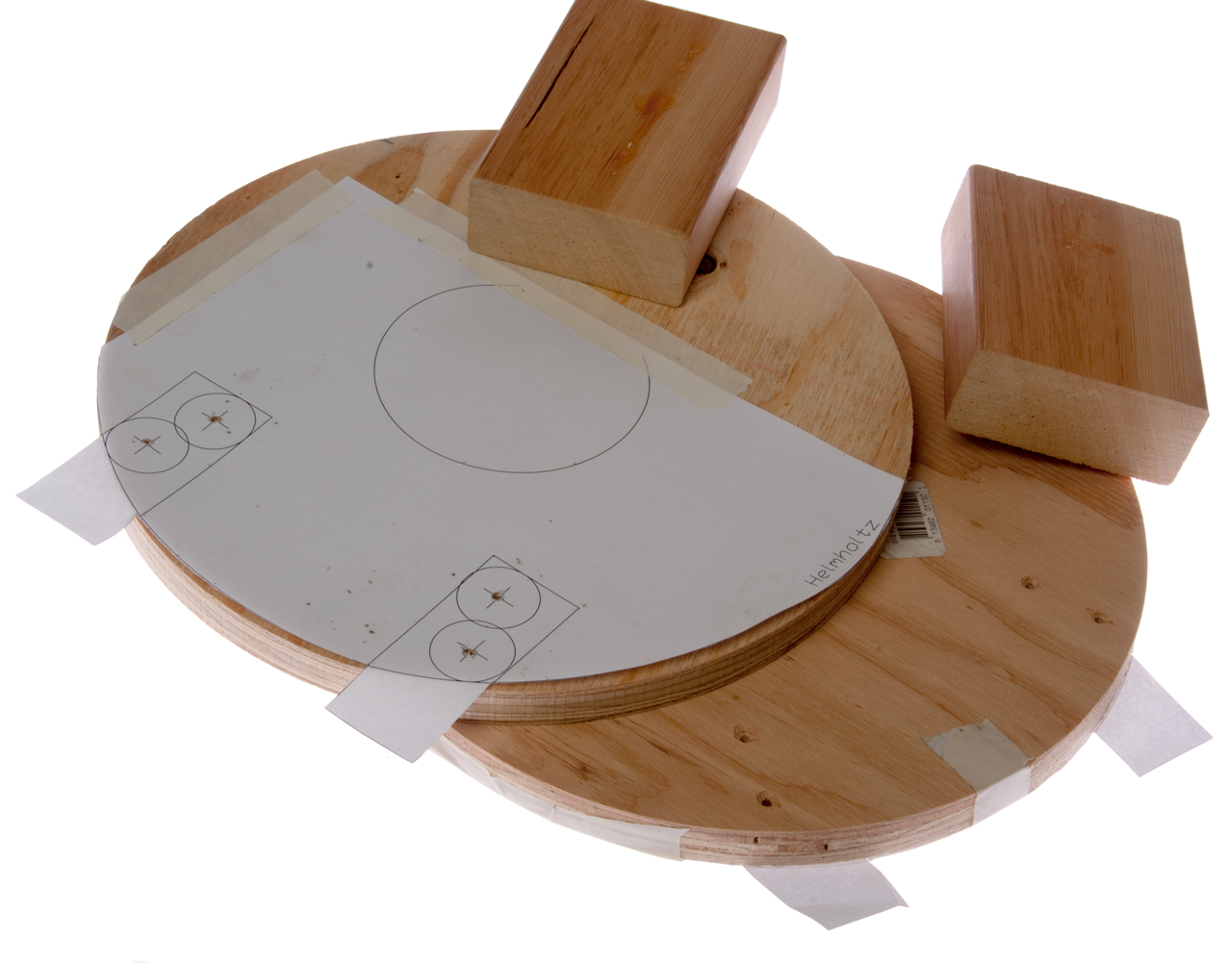
Fig 1
2 ea 12" dia x 3/4" plywood disks marked 23/32" x 11-3/4") 4 holes drilled and countersunk
2 ea 2x4" blocks 5.29" long
Paper template taped to each disk.
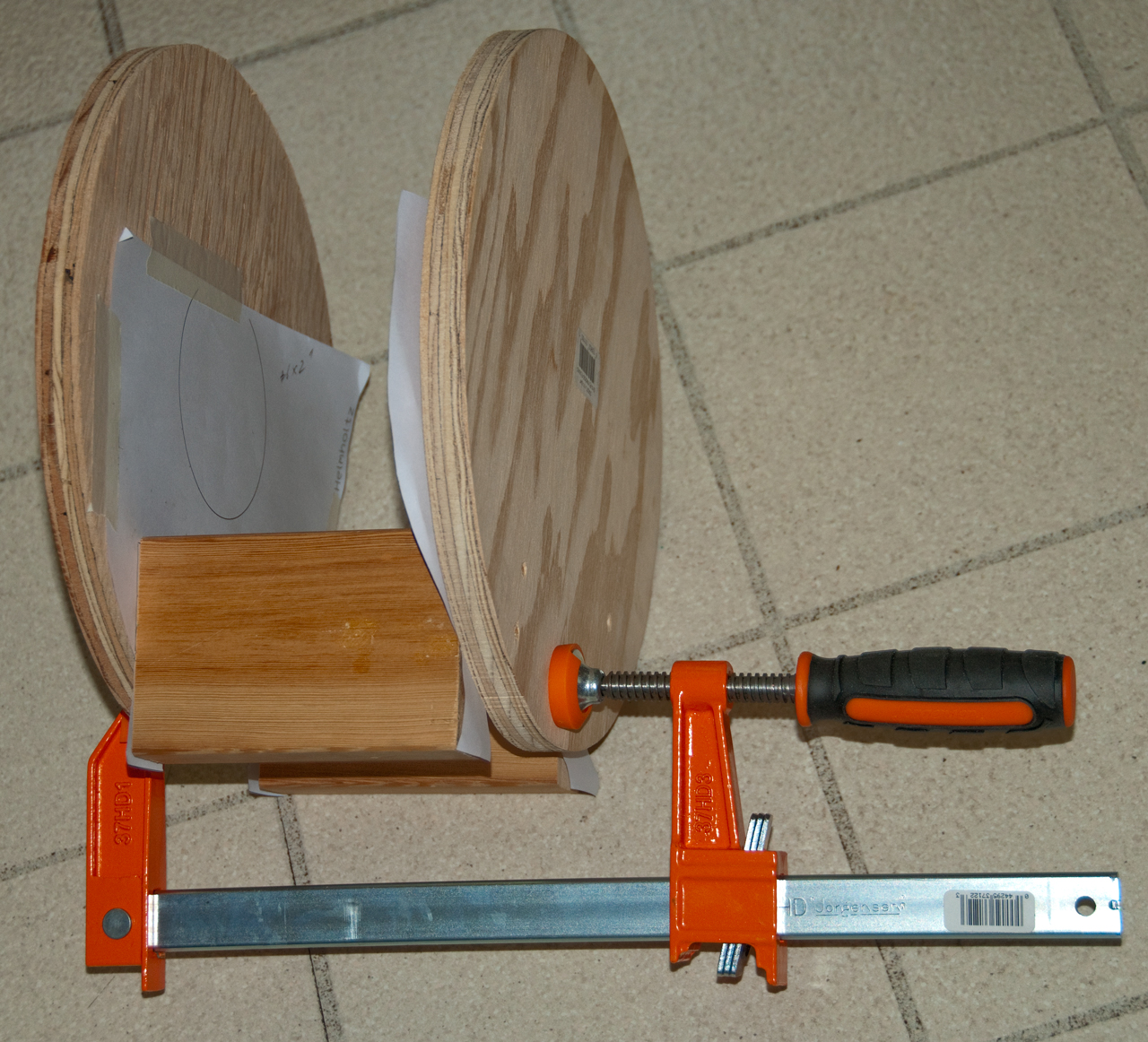
Fig 2 Disks & 2x4 blocks clamped together
using template for location
Then #6 x 2" brass screws installed.
Screws backed out and templates removed
Screws reinstalled in existing holes.
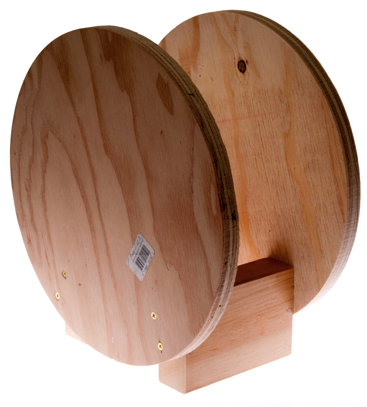
Fig 3 Assembled Helmholtz frame.
Fig 4 After winding 17 Turns of No. 32 AWG magnet wire.
This wire size was chosen to match the 0 to 1 Amp range of my Agilent E3617 lab bench DC Power Supply.
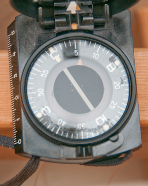
Fig 5 Compass with power supply off
Fig 6 Compass with power supply at about 1.0 Amps
and polarity reversed. With polarity as first connected
the needle only moved a little.
Electrical Parameters
Calculated
Wire Length in one coil = 17 turns * 2 * PI * 11.75" / 12"/ft = 52.3 feet
Resistance of one coil = 164.1 Ohms/1000 ft * 52.3 ft / 1000ft = 8.6 Ohms
Resistance of both coils = 17.2 Ohms
Inductance of one coil = 183 uH (on line calculator)
Frequency where inductive reactance equals coil resistance = 17.2 /(2 * PI * 183E-6) = 15 kHz
Power supply reads 20.9 Volts at 1.000 amps, or 20.9 Ohms including coil pigtail wire and clip leads and pressure connections.
The coil constant for generating a magnetic fields: k (Gauss/Amp) = 0.354008 * N (one coil) / r (inches)
For this coil: k = 0.354008 * 17 / 5.875 = 1.013 Gauss/Amp
Applications
Earth's Field
A single Helmholtz coil, if orientated so the Earth's field vector is along the centerline of the coil can be used to cancel the Earth's filed. Another way to do that would be to use three Helmholtz coils (X, Y and Z) and adjust the polarity and current in each coil so that the Earth's field is zero at the center. For many applications these coils are skeletonized so that there's room to work on some device while it's operating, something that is very difficult or impossible to do inside a zero Gauss chamber.
Measuring Magnets
In this application the Helmholtz coil serves as a search coil with uniform sensitivity over a large part of a permanent magnet's field. A Fluxmeter is needed in addition to the search coil and this is accomplished using an op amp (LM324) integrator circuit (100k series input to -In, gnd +In, 0.1 uF feedback cap.
The LM 324 with a single power supply may not be as good as using a split power supply so that the output can go below zero.
Need to work out the math to convert voltage to magnetic filed.
Calibrating Tesla & Gauss Meters
Since the magnetic filed is a linear function of the coil drive current and the polarity of the magnetic filed depends on the polarity of the drive current a wide range of magnetic fields can be generated in a controled way.
While this particular coil was designed for DC current drive it probably will work with low frequency AC drive. If it works at 50 Hz and 60 Hz then it could be used to calibrate probes and/or hand held type Gauss & Tesla meters including Tri-Field meters.
Measuring the Earth's Magnetic Field
By positioning the Helmholtz coil so it's centerline is on a magnetic North - South line and tilting it so it's center line is on the Earth's magnetic vector and then adjusting the total magnetic filed to zero the field inside the Helmholtz coil the total Earth's magnetic filed can be determined.
Other related Coils
Helmholtz Coil (for comparison)
Field Generation
K (Gauss/Amp) = 0.354008 * N (one coil) / R (inches)
Coils separated by R.
For a 3-axis system you need 3 Helmholtz coils at right angles to each other.
Long Cylindrical Coil
Field Generation
K (Gauss/Amp) = (4 * PI E-1) * (Turns/meter)
Note this can be a multilayer coil. Theoretically the coil should be infinity meters long, but 5 or 10 diameters would be practical.
Maxwell Coil (Wiki, QuickField)
Similar to a Helmholtz coil except there's a larger diameter central coil (3 coils total).
K (Gauss/Amp) = 1.176E-2 * N (center coil) / R (meters)
Center coil has N turns, side coils have 49/6 turns.
Center coil is radius R, side coils are radius R * SQRT(4/7)
Side coils are spaced R * SQRT(3/7)
Note: the three coils are located on the surface of a sphere with radius = R.
Braunbeck Coil
Has four series connected coils for each axis.
Haven't found technical details yet. Let me know.
Permanent Magnet measurement
B = (4 * PI E-1) * K (Gauss/Amp) * Maxwells / Volume of magnet (cm^3)
Making Coil Forms, Bobbins
I have some sample bobbins coming, but for most designs you can't buy off the shelf coil forms (aka: formers or bobbins), so they need to be make.
I looked into having custom plastic parts made, but that turns out to be very expensive.
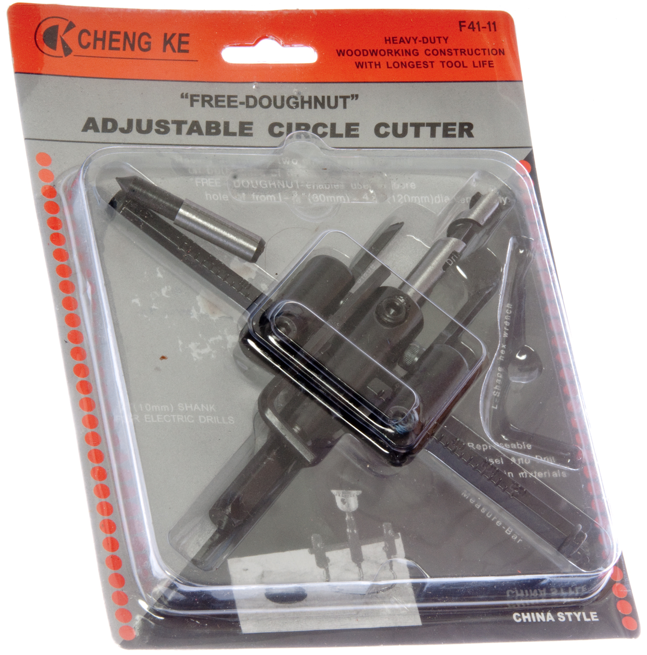
One idea is to use an adjustable hole saw and thin wood to make the end walls to go with PVC pipe and couplings. See Helmholtz Coil For Fluxmeter below.
adjustable hole saw
In the past I've tried to use a prior design adjustable hole saw that had a single cutting bit and it was out of balance because the cutting forces were way off center.
This hole saw has two cutting blades, but they are not used as you might guess. Instead of setting them up to make identical cuts they are setup so that one bit cuts on the inside diameter of the hole and the other bit cots on the outside diameter of a hole. In this way with a single cut you could cut out a "doughnut" or the desired wall shape in a single operation. By having each blade make a different cut they are almost balanced in terms of both making a cut. That would not happen if each blade was set to make the same cut.
Another idea is to use a router and a custom jig to cut circles in thin wood to make "walls" as described above or use the router to cut a groove on the diameter of a wood disk so that multiple layers of wire can be wound with "walls" on either side to hole the shape.
Like the Mini Cut-Off Saw I expect the motor in this router is not as powerful as in a commercial product, but my hope is that it can make a narrow cut without burning up the wood.
There are a bunch of metal parts in the box, maybe what's needed to cut circles?
Harbor Freight 61626 (44914) Router & 68869 Bits
Inside box
Configured for circle cutting.
Minimum radius about 4-1/4" with stock parts,
but it should be easy to make a bracket for
shorter or longer radius values.
1/4 x 3/8" router bit modified by changing bearing
to make 1/4" x 1/4" groove.
1/4" shank.
I found a bit that will cut a 1/4" wide and 1/4" deep slot. It's a modified eBay 1/4" router bit with the title:
1 pc 1/4" SH Flooring for Undercutting Slot Floor Router Bit sct-888 from seller ghsu2ia3
It has been modified by changing the bearing to another bearing where the OD is slightly larger so that instead of getting a 3/8" deep x 1/4" slot the slot is 1/4" deep.
This will allow modifying the plywood disks so that the windings fit into the 1/4 x 1/4" slot.
Using 24 AWG wire:
11 turns per layer and 11 turns deep for 121 turns with an average diameter of 11.75 - .25 = 11.5" will take 364 feet of wire per coil or a total of 728 feet.
The resistance for both coils will be about 18 Ohms which is close to the desired 15.0 Ohms. A few turns could be unwrapped to get it correct.
I have a spool that weighs 14.4 oz (0.9 pounds) and for 24 AWG it's about 800 feet/pound so I have a little less (the metal spool has some weight) than 720 feet. It looks like I need more wire.


Human Head
It turns out that many animals have a magnetic sensor that they use for navigation. Humans have a protein (cryptochromes – CRY1 and CRY2 Wiki) that have magnetic properties, but it's not clear of humans make use of the magnetic property. These cryptochromes are located in the retina so maybe the effect shows up in vision. I've read that birds eyes also include magnetic sensors and the speculation is that whatever they see is modulated by the magnetic field vector. Maybe when migrating they fly toward the brightest (or darkest) scene?
In animal experiments it's not clear how strong a magnetic field is used, but I expect the final field the animal experiences is about the same as for the Earth (0.5 Gauss). But to do a human experiment it would be better to increase the field strength to make it easier to detect the effect. Since MRI machines (Wiki) use very strong magnetic fields the same safety precautions they use would apply here. Note if there's any ferrous metal in someone's eye it must be removed prior to an MRI because the metal particle would be attracted to magnet and would act like a knife as it moved, a very dangerous thing. Note MRI magnets in the U.S. can go up to 4 Tesla ( 40,000 Gauss).
A coil to fit a human head might rest on your shoulders. Rather than a 3-coil system a single coil that could be positioned in 3 mutually orthogonal directions would be easier to make and use. That means you need to be able to put your head through the center of a coil and that the distance between coil is larger than the widest part of you head.
When in place the location of your eyes needs to be in the uniform field part of the Helmholtz coil.
Ruska Helmholtz Coil
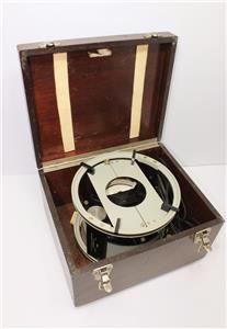
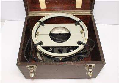
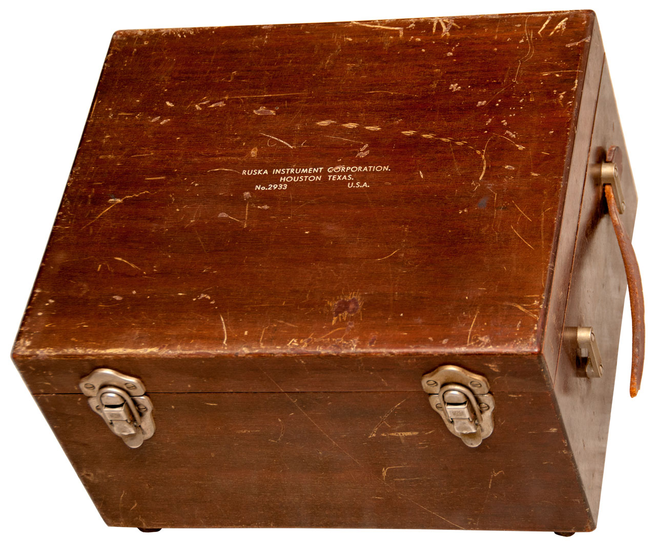
This showed up on eBay and I got it because it contains a Helmholtz coil. There is also some type of test instrument and a carry cars for both the coil and test instrument.
Description
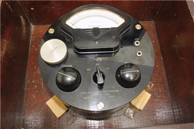
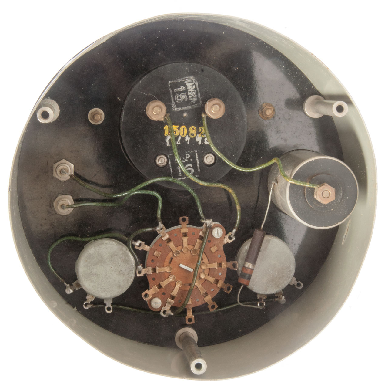
This is a power supply and Helmholtz coil.
Power Supply
A 1.5 Volt (nominal) "D" cell battery is connected in series with a Coarse ( 1k Ohm) pot and a Fine (50 Ohm) pot and a fixed 100 Ohm resistor and a 0 to 10 mA meter.
The minimum current (fresh battery) = 1.6 /(1000 + 100 +50) = 1.4 mA
The maximum current (fresh battery) = 1.6 / 100 = 16 mA
The On - Off - On switch reverses the polarity of the output while not effecting the polarity the meter reads. This allows for how the coil is installed (up or down) and which of the Earth's hemispheres (Northern or Southern).
Epislon = (2 * C * I) / (R1 - R2)
where:
C is the Coil constant (printed on the coil as C=29.2)
I is the current
R1 & R2: Unknown.
At first I thought that they would be the Coarse and Fine pots, but that's not the case. There are a few arguments against that:
The equation shows R1 - R2 and that should be R1 + R2 if this was related to to circuit resistance,
The fixed 100 Ohm resistor is not included,
There is no easy way for someone to know the values of the Coarse and Fine controls,
Dimensional analysis of the equation would not make sense.
The Coil and it's attached leads measure a total of 4.6 Ohms.The connector on the coil is a dual banana plug with 3/4" center-to-center spacing so it plugs directly into the Fluke 87 V DMM.
It turns out that there was a poor connection between the coil leads and the dual banana plug. After taking it apart and reassembling the reading is 0.4 to 0.5 Ohms.
Measuring right at the coil wires it's more like 0.2 Ohms.
These values for the coil resistance arr too low, see the Electrical Parameters of my home made Helmholtz coil above. While I would not expect this coil to be the same, it should be closer to those values.
Operation
When a fresh "D" battery is installed the the coil connected an R.B. Annis 0.5 - 0 - 0.5 Gauss meter shows only a very small deflection at max current (slightly above the 10 mA meter max reading). I would have expected to see a much larger reading.
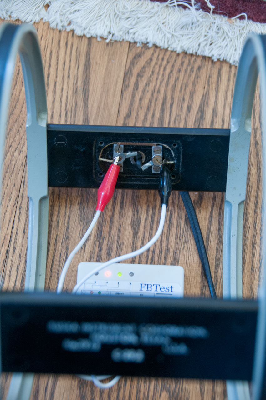
The Flyback Tester shows a short (Fig 4 below). That would explain why it's not generating the needed magnetic field. Disconnecting the lead wires inside the Helmholtz coil and Flyback testing at the coil wires also shows a short (Fig 5 below). So it's likely an internal coil short that causing the problem.
Here are some eBay photos from the listing:
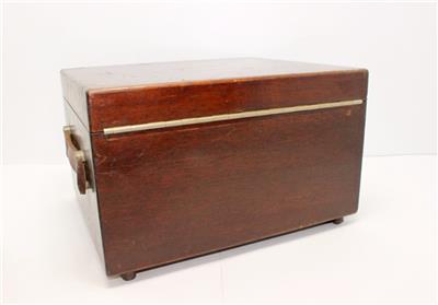
Fig 1 Carry Case, Coil & Unit
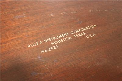
Fig 2
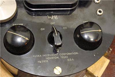
Ruska Instrument Corporation
Houston, Texas
No. 2933, U.S.A.
Fig 3
Fig 4 0 to 10 mA DC
Fig 5 Coarse, On-Off-On, Fine
Fig 6 Battery Compartment
Fig 7 Ruska Inst Corp
Houston, TX
No. 2933 U.S.A.
C=29.2
Fig 8
Fig 9
Fig 10
Fig 11
Fig 12
Fig 13
Photos
Fig 1
Fig 2
Epislon = (2 * C * I) / (R1 - R2)
Fig 3 The power supply is attached to the
case by three screws.

Fig 4 The Flyback Tester shows a short.
Fig 5 Short is not in coil leads, but it the coil itself.
To measure the vertical component of the Earth's magnetic field a Torsion Magnetometer is used.
The Ruska Helmholtz coil may be related to the below instrument (based on patent 2501538).
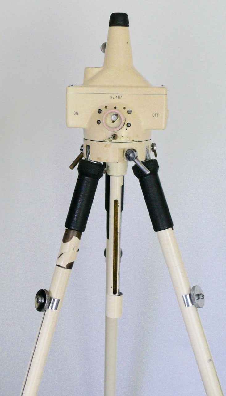
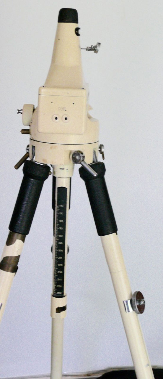
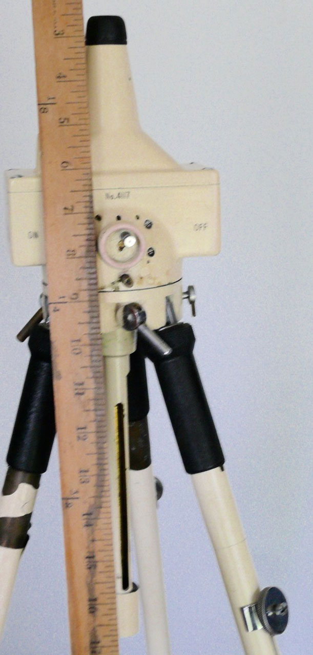
M3 Coil Magnetic Survey Instrument
Description
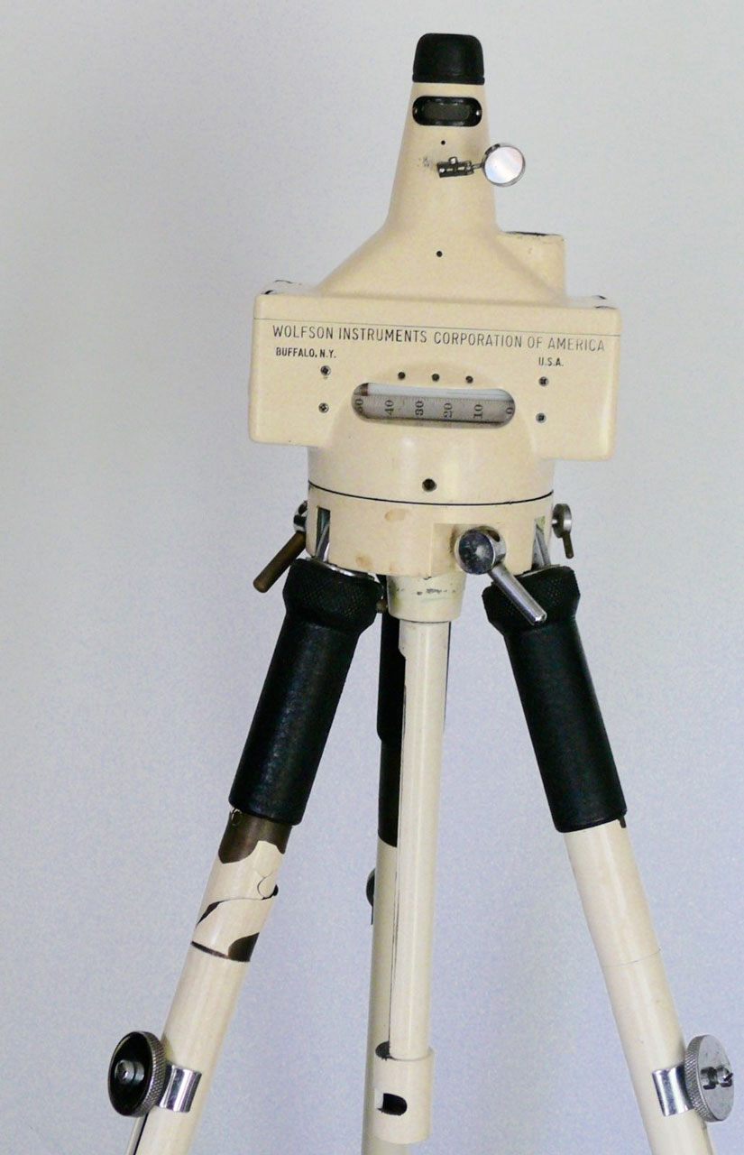
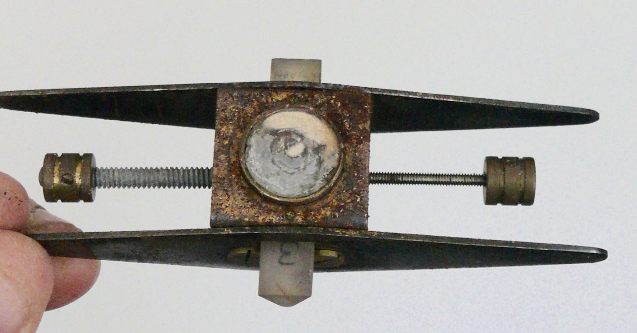
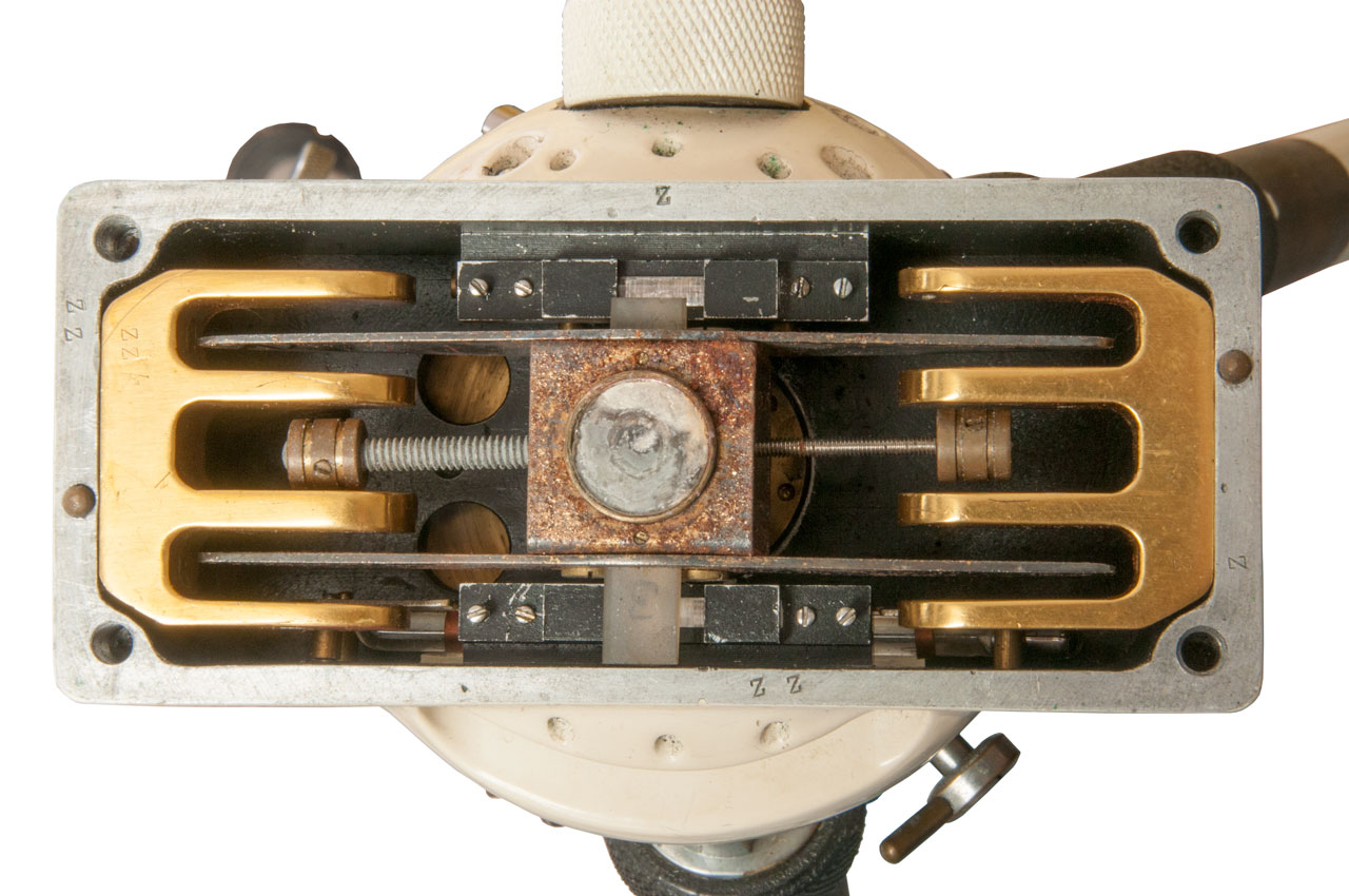
This is a "magnetic balance" used to measure the vertical component of the Earth's magnetic field.
Ruska patented one of these, see 2501538 just above in 1935, but Askania Werke Ag patented one in 1935.
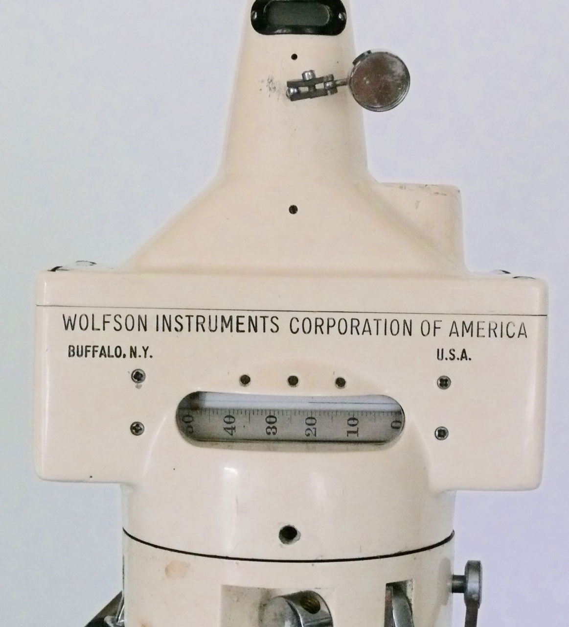
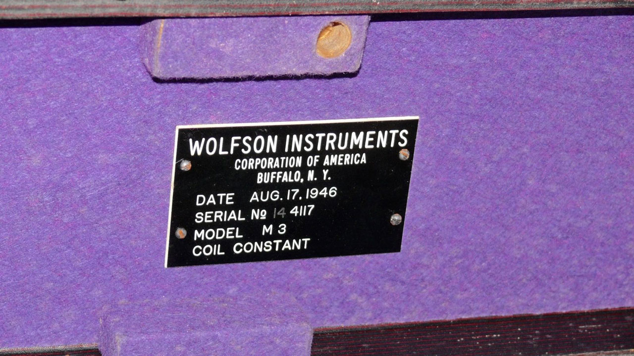
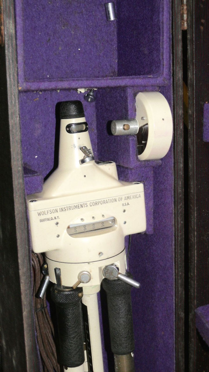
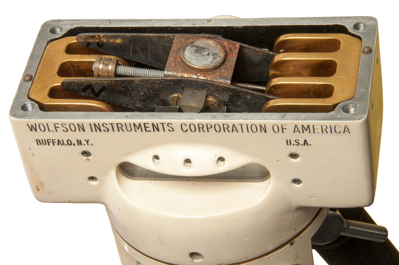
Label: Wolfson Instruments Corporation of America, Buffalo, NY, USA
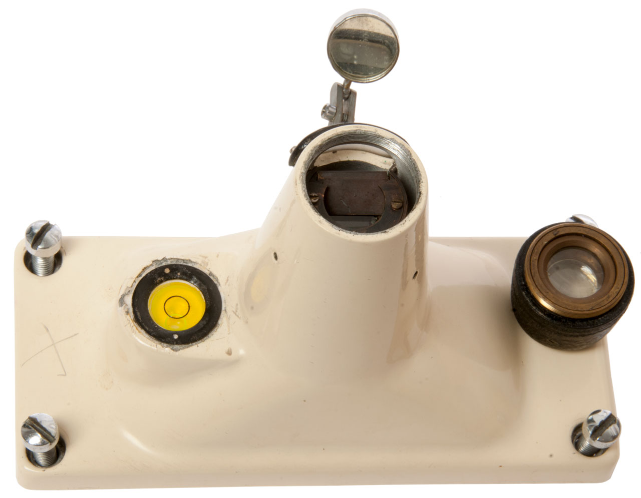
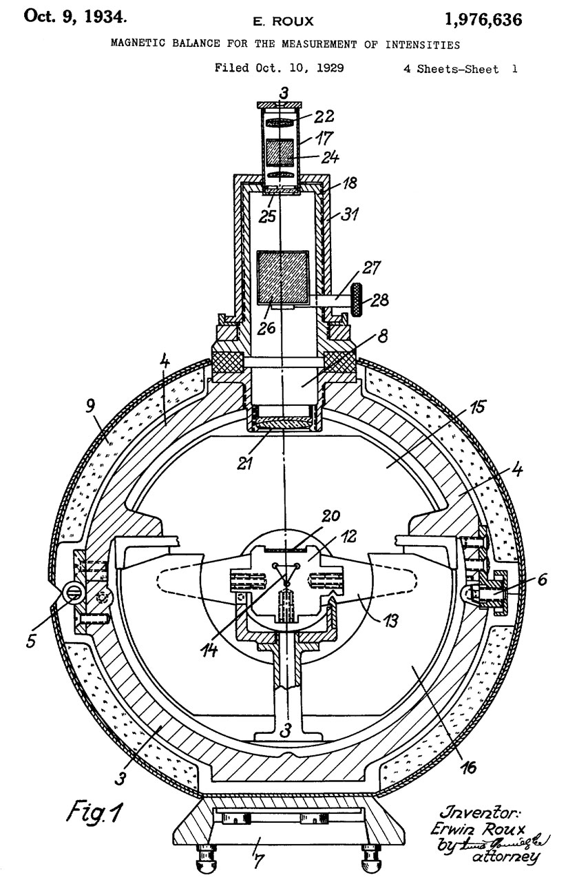
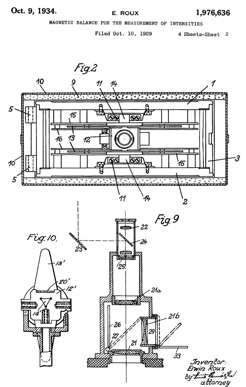
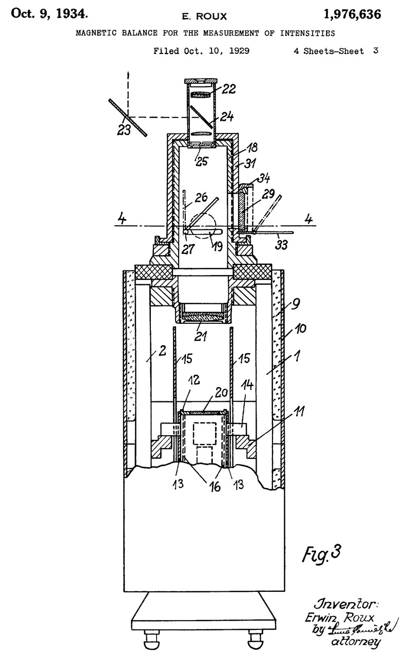
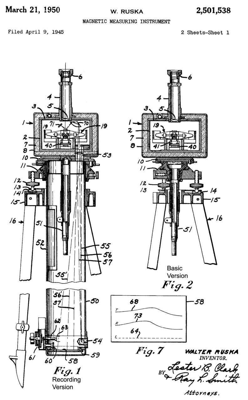
There is what amounts to a bar magnet (19)balanced on a knife edge suspension. If placed in a zero magnetic filed the bar magnet would be balanced, but if placed in a vertical magnetic field the bar will be pulled down. There is a mirror (28) on top of the bar that causes a fiducial line to appear on the 0 to 50 scale when light is shined into the side of the telescope. There is a similar 0 to 50 scale on the body of the instrument of unknown purpose.
There probably is a coil that can be driven from the external terminals (Fig 5) and with the correct polarity and current can be used to bring the bar magnet back to the zero balanced position. Knowing the coil constant and the current through it would allow calculating the strength of the field. Maybe the 0 to 50 scale means 0 to 0.5 Gauss and is a direct measure.
Operation
Photos from eBay
Fig 1
Fig 2
Fig 3
Fig 4
Fig 5
Fig 6
Fig 7 Note the 0 to 50 scale in the base unit.
Fig 8
Fig 9 Compare this to 2501538 Fig 6 Sheet 2 above.
The circle at the center (Fig 6 #28) should be a mirror.
Fig 10 Thr purpose of the three rods and misc
hardware is still TBD (31 Oct 2017)
Fig 11
Fig 12 White disk at right is a compass.
Photos
Note 1: the reason for the end marked "S" to tip down may be do to either the Earth's magnetic filed or mechanical unbalance in the magnetic element. This is why the Helmholtz coil is needed.
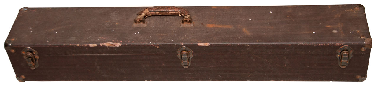
Fig 100 Carry Case
Fig 101 Open Carry Case
Three rods of different length at front center.
All of them are magnets.
Fig 102 with bubble centered & compass needle at North
the Long axis of the body is North-South
Fig 103 I marked N andS on the inside and
outside of both arms then see in the photo
that someone already made some marks.
There is an optical 0 to 50 scale in the top optical assembly.
Note because of the three "grooves" on the bottom of the mag element it can only be installed one way in order for the On/Off knob to work. But can be installed either way with the knob is in the On position.
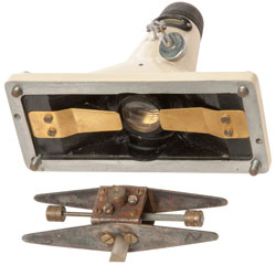
Fig 104 The knob at top raises (Off/caged) and lowers (On/free) the magnetic element. I think the bronze colored fingers are magnetic dampening. The coil contacts at the left appear to be connected to a coil in the base hidden from view.
Fig 105 The Quartz triangle is off center.
The magnetic element does not sit with good
alignment.
Fig 106 After pushing the Quartz triangle beam to be more centered and raising and lowering the On/Off knob and tweaking the position,
the magnetic element tips with the end marked "S" down. Reversing the magnetic element also has the "S" end tipping down.1
Fig 107 The 0 to 50 scale is the straight part
on the back wall near the light input opening.
By cancelling the Earth's vertical field the element mechanical balance can be adjusted without any effect due to magnetic moments.
Patents
1803405 Electromagnetic method of underground exploration, Norman H Ricker, 1931-05-05, - measuring Earth's impedance to discover minerals (See: Metal Locators)
1976636 Magnetic balance for the measurement of intensities, Erwin Roux, Askanid Werke, Oct 9, 1934, 33/348, 324/259, 33/355.00R
GB448647 eSpaceNet Improvements in magnetometers, E R Watts & Son, 1936-06-12, - "H" shaped magnetic balance
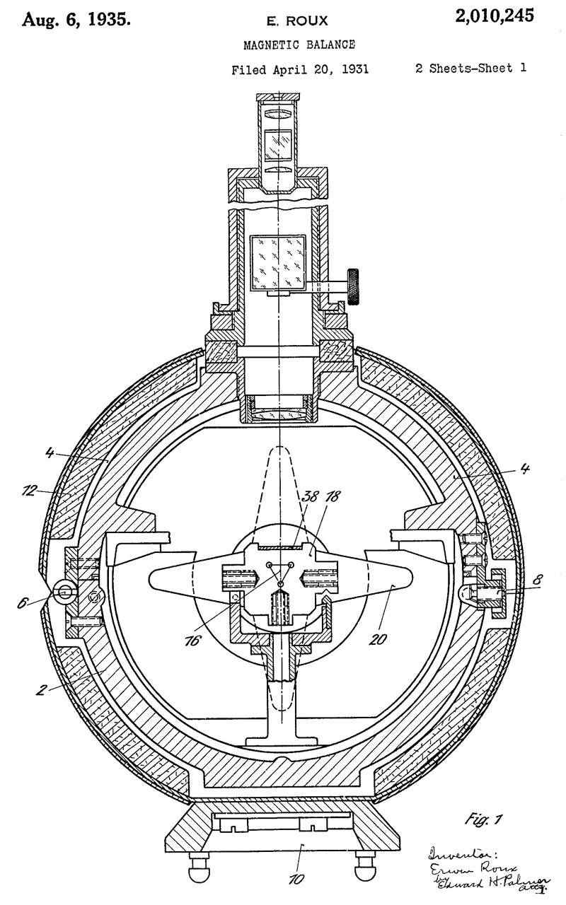
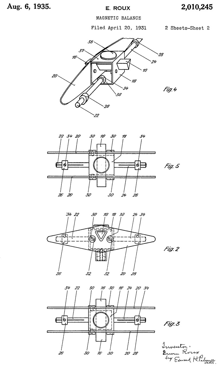
2010245 Magnetic balance, Erwin Roux, Askania Werke Ag, Aug 6, 1935, 33/315, 324/259, 324/224, 33/355.00R, 33/356 -
The Construction of the magnetic assembly is about the same as the Ruska version.
Sheet 1
Sheet 2
2501538 Magnetic measuring instrument, Walter Ruska, Ruska Instr Corp, Filed: Apr 9, 1945, Pub: Mar 21, 1950, 346/107.3, 324/259, 346/25, 177/178 - " for locating magnetic anomalies"
Ruska adds a base station recording version, the field version is essentially the Askania in the above patent.
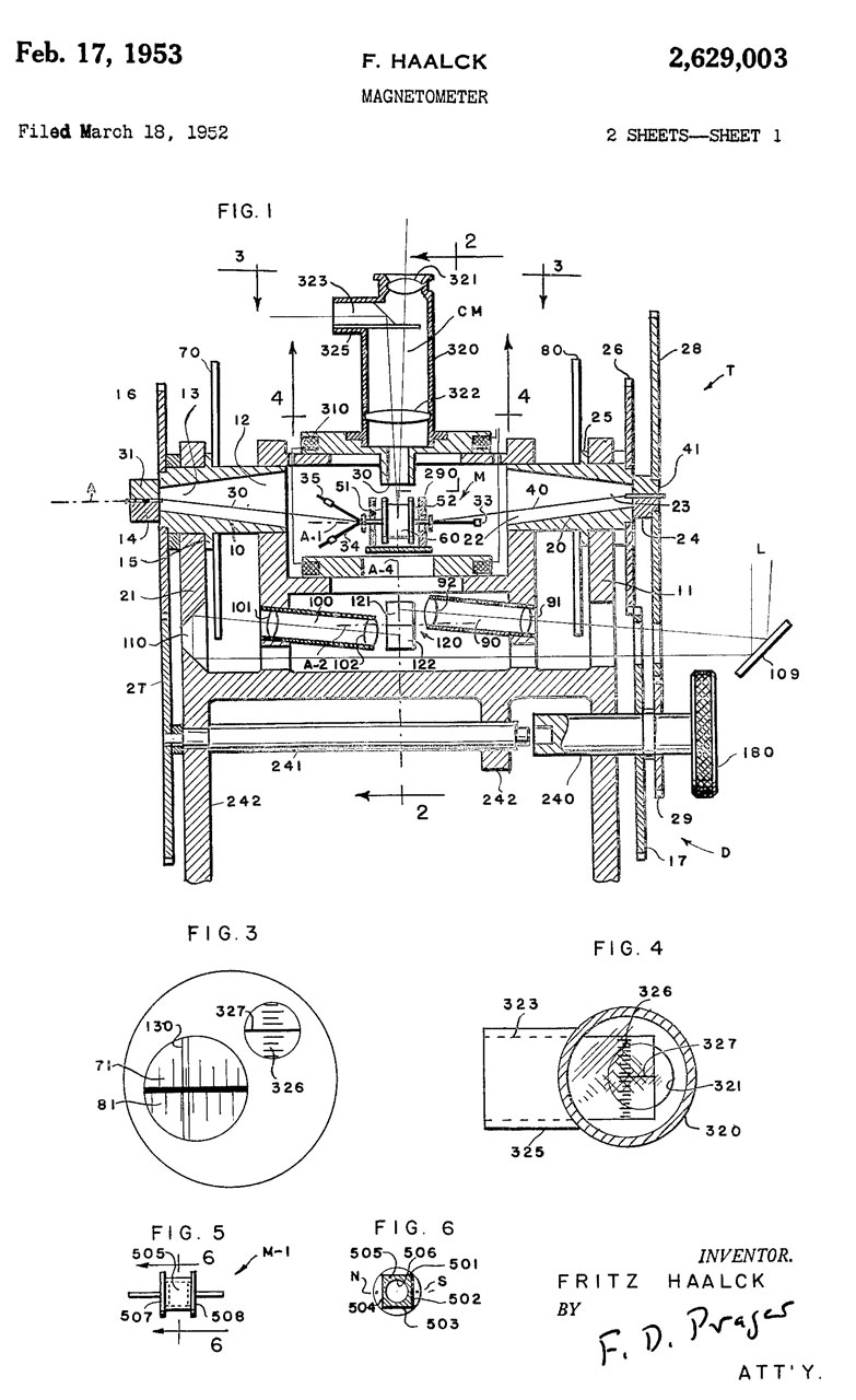
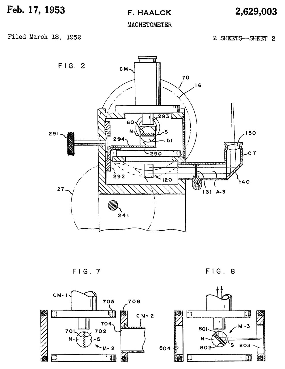
2629003 Magnetometer, Fritz Haalck, Askania Werke Ag, Feb 17, 1953, 324/259, 33/355.00D, 359/439, 337/94 -
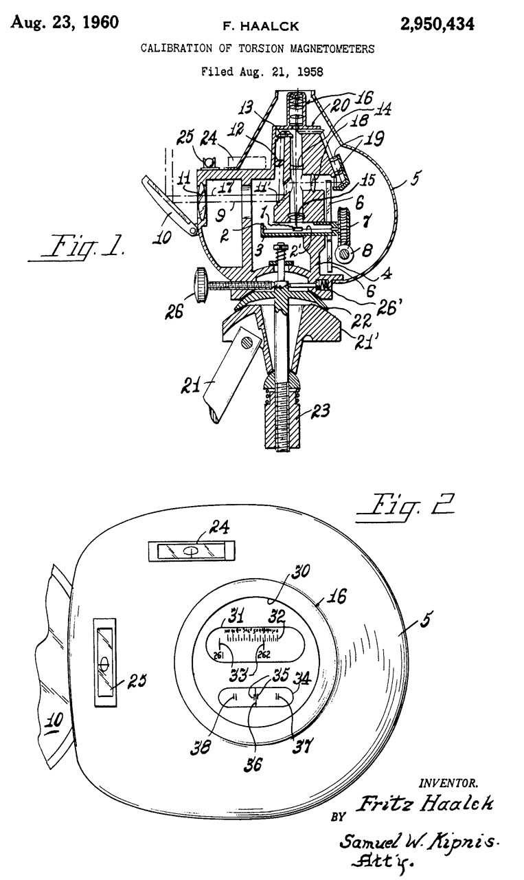
2950434 Calibration of torsion magnetometers, Fritz Haalck, Askania Werke Ag, Aug 23, 1960, 324/202, 324/259, 310/152 -the aim was to replace the Helmholtz coil calibration setup. Makes use of both the Earth's vertical and horizontal components.
5432445 Mirror image differential induction amplitude magnetometer,Robert C. Dinsmore, Kelvin Shih, Dinsmore Instrument Co , 1995-07-11 - one nano Tesla (1 nT) or smaller - mirror image differential induction amplitude magnetometer (MIDIAM) -


Waugh MW3 & MW4 Magnetometers
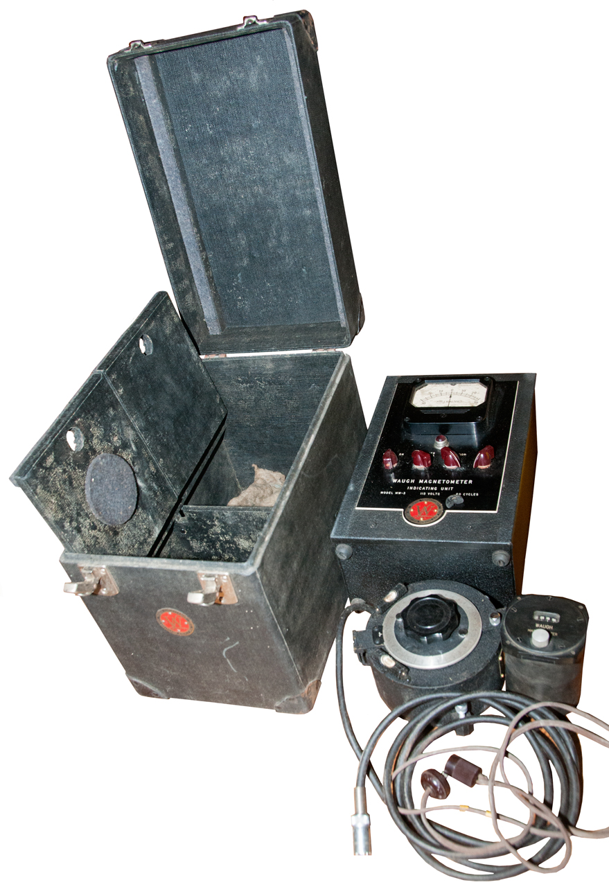
Got this set on eBay Feb 2022. "Patent Applied for" appears on some of the items, but so far I have not been able to find any.
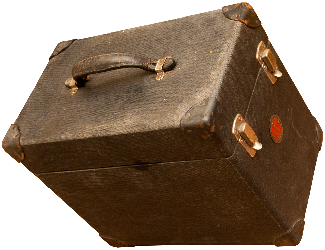
Carry Case (Fig 1, 3)
This has a round metal medallion "Waugh Laboratories, 420 Lexington Avenue New York".
There are two trap doors under the main compartment that holds the Magnetometer read out.
The front compartment holds the MW3 compass rose sensor that has leveling vials and sights.
The rear compartment holds a line cord and a MW4 sensor that may fit an aircraft instrument panel?
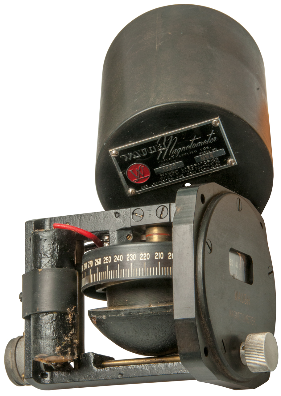
Magnetometer (Fig 2, 3, 5 & 8)
Metal ID Plate
Waugh Magnetometer
Patent Applied for
Mod No. MW 3 Ser. No. 1637
Volts: 115 Cyc. 60
and in addition the round Waugh Laboratories" medallion like on the carry case.
The meter is marked -30 .... 0 ..... +30 Milligauss. Note this is less than the Earth's field (Wiki) which is in the range of 250 to 650 milligauss.
Controls
Off - On switch
Multplier Switch: 1, 10, 30, A (full scale ranges of +/-30, +/- 300, +/-900 and what does "A" mean?)
Calibration Pot
Zero Pot
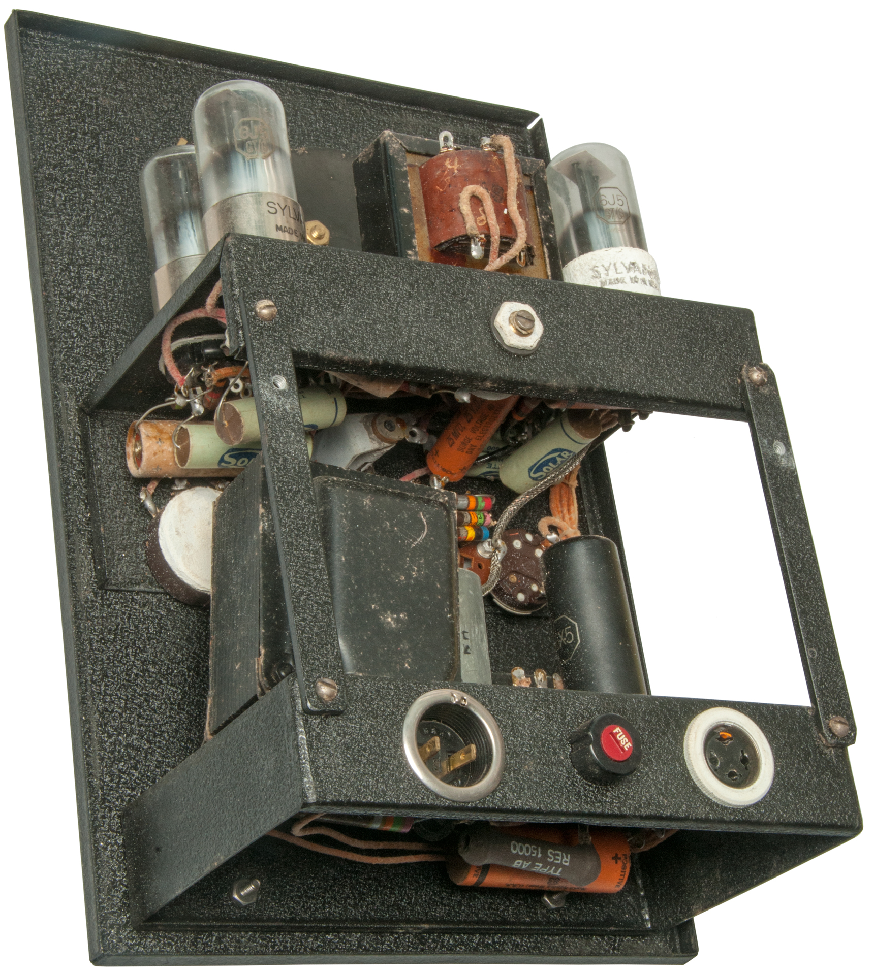
Tubes
Top deck: 3 each 6J5 and a 6SN7
Bottom deck: one each 6X5.
Sensor 4-socket connector
Pin
Function
1
AC drive
2
Ground
3
Sensor
4
AC drive
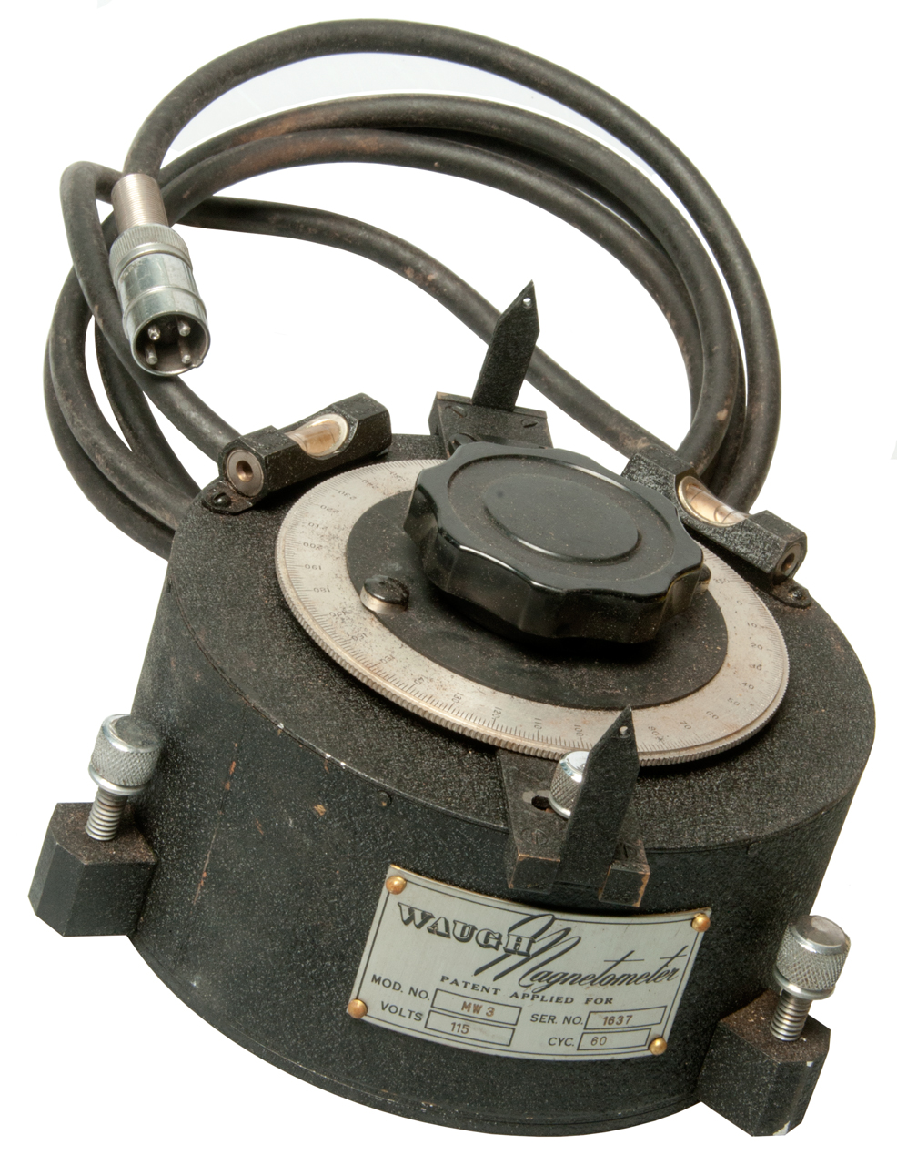
MW 3 Sensor (Fig 3, 4)
This is designed to be placed on a level surface and leveled. Then the compass rose can be turned to find the peak or null direction.
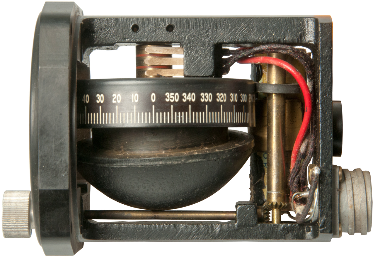
MW4 Sensor (Fig 3, 6 & 7)
Metal ID Plate:
Waugh Magnetometer
Patent Applied for
Serial No. 1627 Model No. MW4
Waugh Labratories
Division of Waugh Equipment Co.
420 Lexington Avenue New YorkThis appears to be designed to fit into a standard aircraft instrument panel cutout. Or maybe that size cutout in a ground vehicle. The knob on the front panel has two functions.
First it rotates the sensor in azimuth by means of the rubber tire at the top of the vertical brass shaft. Second if the knob is rocked back and forth the horizontal brass shaft rubs on the bottom of the hemispherical sensor housing and causes it to tilt left or right.
There are three slip rings on the sensor so it's most likely an aircraft type "Y" sensor. This is the type used in aircraft. See MC-1 Magnetic Compass Calibration and the Sperry Master Flux Valve.
Line Cord (Fig 3)
Photos
Fig 1
Fig 2
Fig 3
Fig 4
Fig 5
Fig 6
Fig 7
Fig 8
Patents
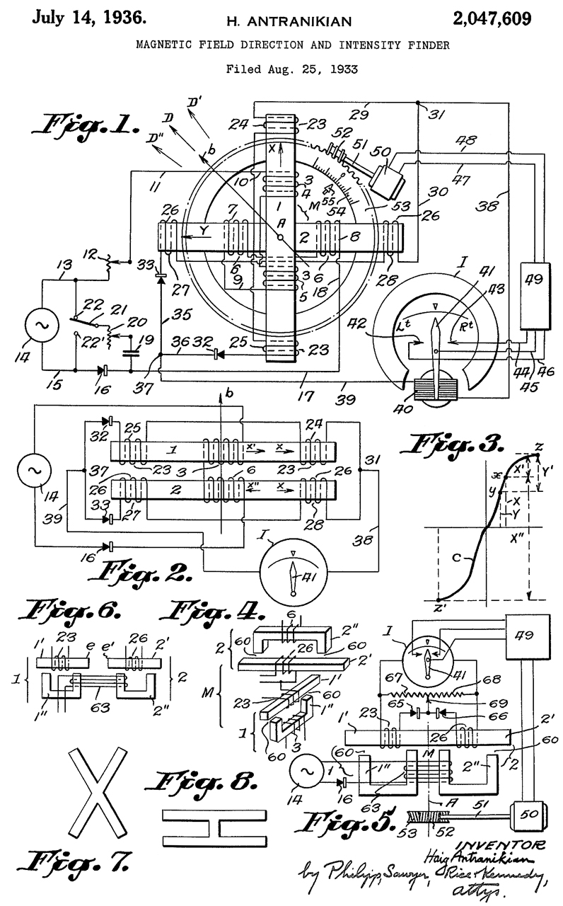
2047609 Magnetic field direction and intensity finder, Antranikian Haig, 1936-07-14, 33/301; 33/362; 324/247; 340/870.33 - improvement on the Earth Inductor compass that required rotating the sense coil with a motor.
This is the earliest patent to use the phrase "flux valve" and so is that start of the "Y" type magnetic compass. These were used mostly in aircraft.
There was no company assigned.
2321355 Surgical probe for locating foreign metal particles in body tissue, Berman Samuel, Waugh Equipment, 1943-06-08, 600/11; 324/239; 324/326; 336/233; 340/686.1; 324/67; 324/260; 336/90; 336/170-
cited by 25 patents.
2321356 Locator, Berman Samuel, Waugh Equipment Co, 1943-06-08, 600/11; 324/67; 324/326; 336/75; 336/107; 336/130; 336/233; 340/686.1; 324/243; 336/66; 336/90 - "... determining the presence and location of metallic particles in body tissue..."
2437455 Locator, Berman Samuel, Waugh Equipment Co,1948-03-09, 323/347; 324/243; 324/326; 336/133; 600/11; 336/75; 336/134 - "... determining the presence and location of metallic particles in body tissue..."
2469137 Vibration indicator, Elbie C Strong, Waugh Equipment Co, 1949-05-03, - based on a balanced transformer
2450868 Variable transformer, Variable transformer, Berman Samuel, Waugh Equipment Co, App: 1943-04-13, Pub: 1948-10-12, - for use with above devices to balance windings.
2549567 Magnetic-type object detector, Berman Samuel, Waugh Equipment Co, 1951-04-17, - transformer primary AC driven, balanced coils detect vibration.


Fluxmeter
Description
Measuring the number of magnetic flux (Wiki) lines is different than measuring the strength of the magnetic filed at one point, like done with a Gaussmeter. The fluxmeter integrates all the flux lines and so is a good way to measure a permanent magnet.
Integrating Op Amp Fluxmeter
Rather than using a Ballistic Galvanometer Fluxmeter this is a more modern approach.
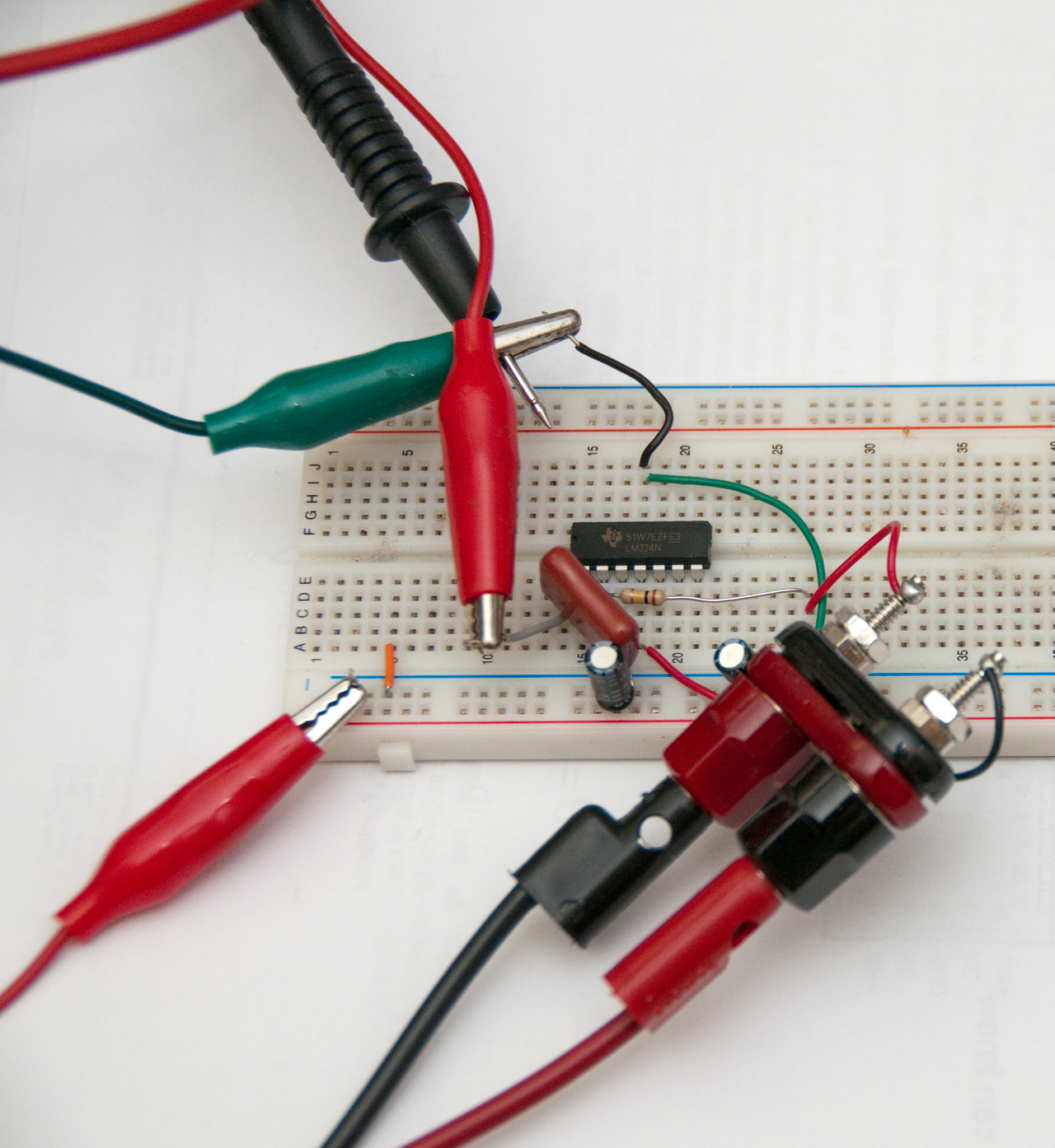
Fig 7 LM324 Integrating Voltmeter (Fluxmeter)
Black probe & nearby red clip lead to Fluke 87 DMM.
Green clip from power supply ground.
Lower left red clip from power supply.
Banana cables from Helmholtz coil.
Output locked to -0.1 because of single power supply.
Fig 8 HP E3631A to provide + & - rails for op amp.
Now output drifts -0.1 volts/second.
Removing cap causes output to go to -Vc.
Yellow wire is to short cap (reset).
The Helmholtz coil is sitting at the top of the frame.
It's connected to an integrating op amp circuit acting as a Fluxmeter. Fig 7 circuit.
Annis Magnetometer Earth's field M25
The result is not what's expected.
1. the positive and negative deflections are not equal.
2. the scale factor is not 1 Gauss/Amp.
Why? Let me know
ans: getting the coil exactly on an East-West line and getting the magnetometer exactly aligned with the coil axis is an iterative process. After going back and forth I finally got the meter deflection to be symmetrical and at very close to 0.25 Amps for 0.5 Gauss deflection of the meter. But was expecting 0.5 Amps for 0.5 Gauss????
W.W. II Fluxmeters

TS-15 Fluxmeter
The W.W.II Signal Corps Fluxmeter TS-15 has two meters. The probe is a meter movement without any magnet. It's placed into the field to be measured (properly orientated with a fixture). Then the main box is used to adjust the current through the probe until the probe shows full scale. Since the probe meter movement has a known calibration factor (maybe 100 uA full scale with a magnetic filed of xxx) when the meter is at full scale the product of field strength and current is some constant. If the actual field at the probe meter was 10 times the reference field for 100 uA then it would only take 10 uA to get a full scale indication. At that setting the main meter has a deflection proportional to the current, but the meter is calibrated in magnetic field.
The TS-15 was used to measure W.W. II Magnetron (Wiki) magnets and includes fixtures to properly position the probe meter in the gap. There may be other fixtures for various models of Magnetron.
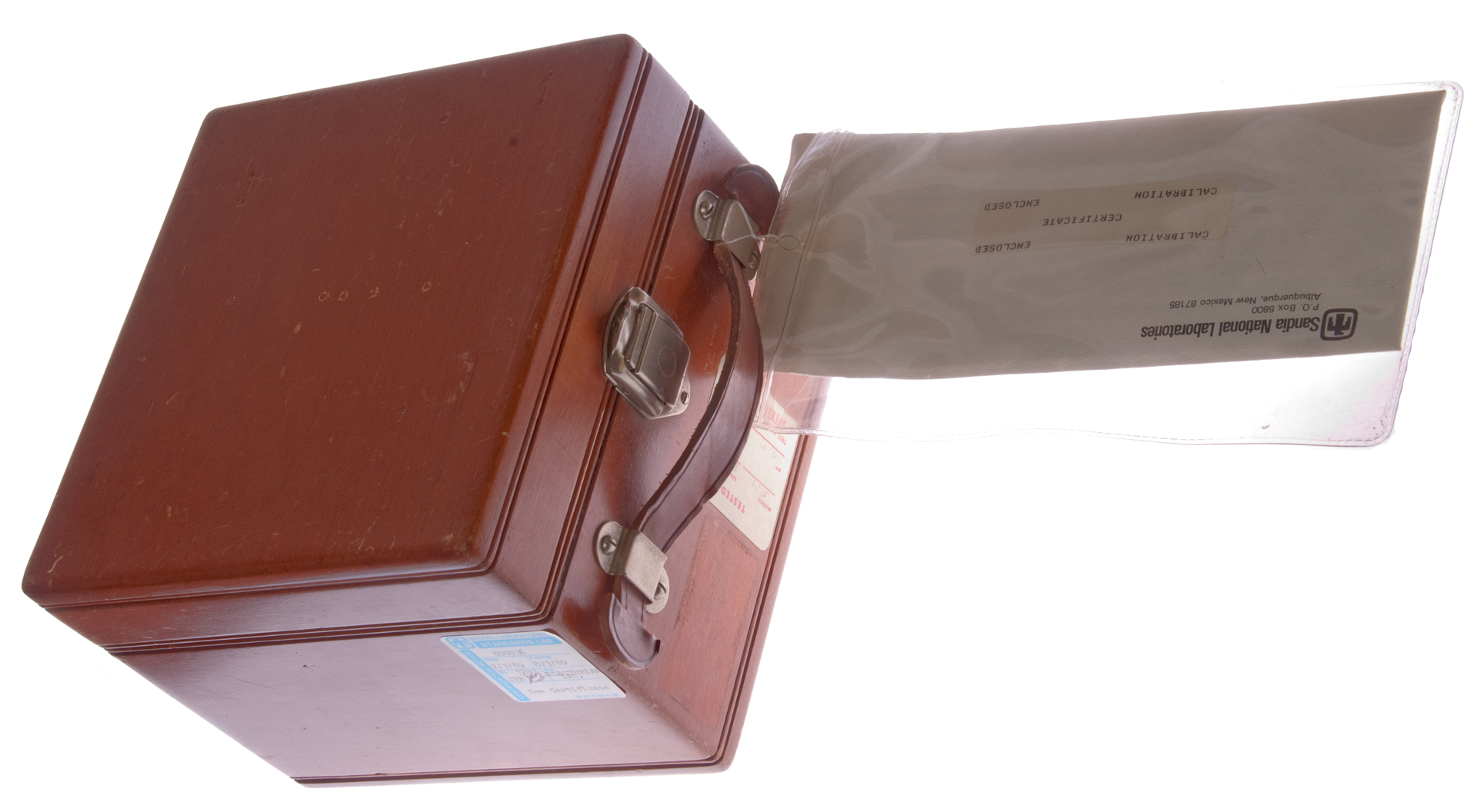
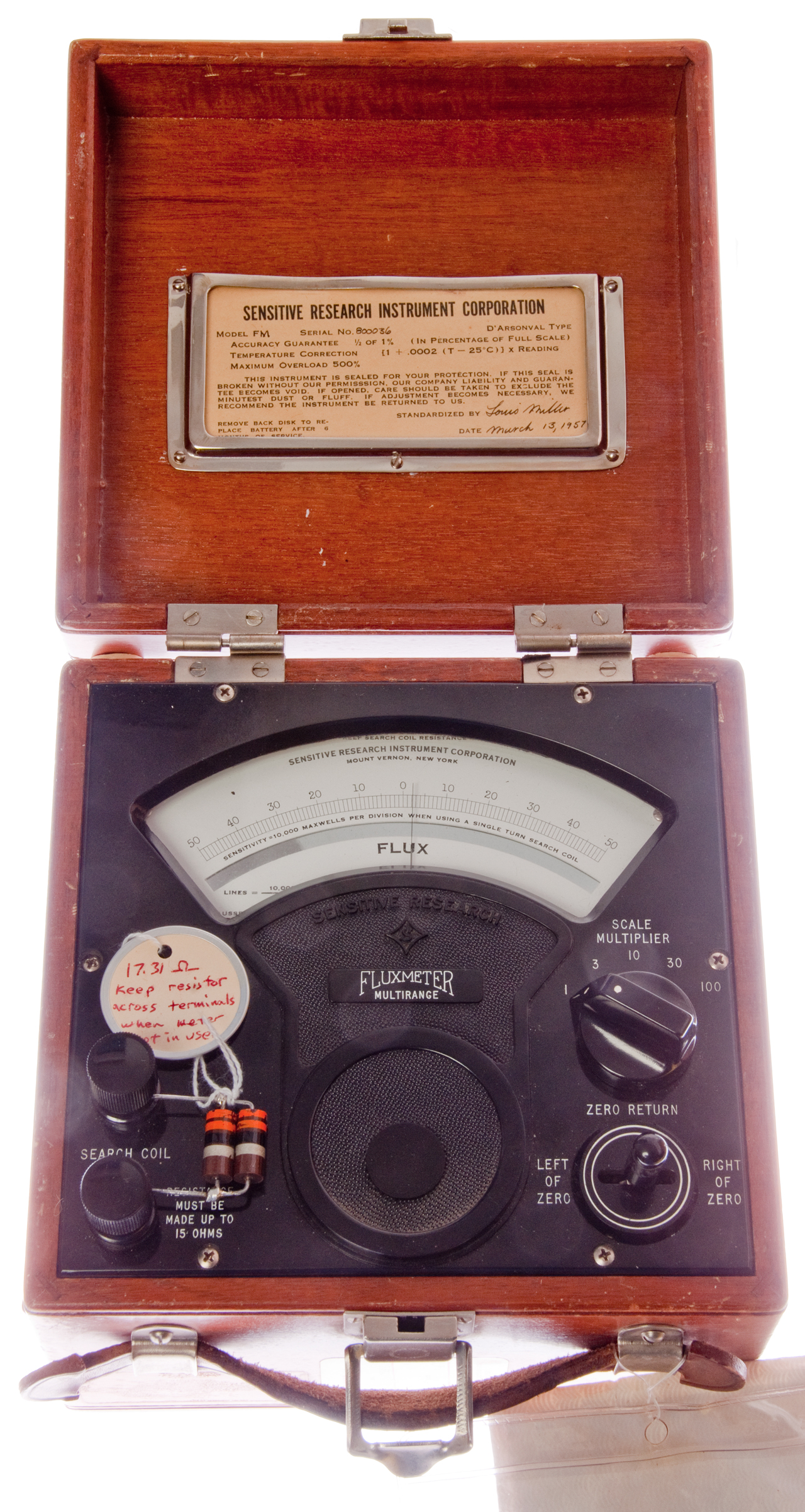
Sensitive Research Instrument Co. Model FM Fluxmeter
NYS Filing Date: MAY 13, 1949, INACTIVE: Termination (Apr 09, 1993). They were in business for about 44 years.
1981 Sensitive Research Catalog 76 (pdf)
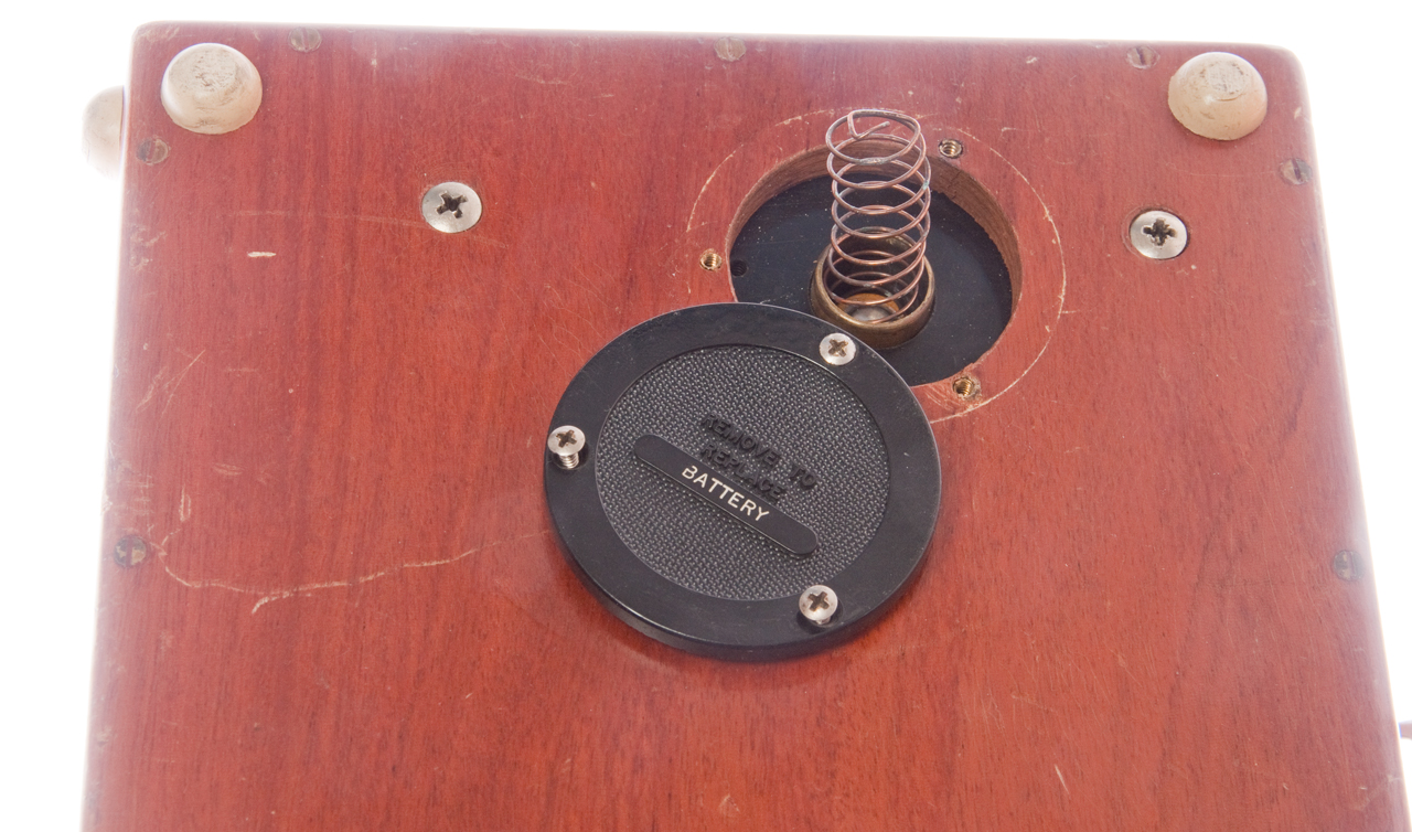
1. StandardsThe FM fluxmeter is custom made by Sensitive Research and has a much larger permanent magnet than typical D'arsonval meter movements (Wiki). But unlike the common meter movement the Ballistic Galvanometer (Wiki) used in this instrument has "...a high moment of inertia, arranged so that its deflection is proportional to the total charge sent through the meter's coil." It also does not have a spring to bring the needle to zero, but instead uses a AA battery and a Left-Off-Right switch to move the meter to the center zero position.
2. AC/DC Polyrangers
4. AC/DC & AC Reference Standard Dynamometer & Moving Iron Instruments
5. AC/DC Electrodynometer Wattmeters
6. AC/DC Electrostatic Voltmeters & Voltage dividers
7. AC/DC Audio & RF Thermocouple Instruments
8. Magnetic Testing Instruments (FS, FM, FC, FLV, FLVC, MAT, EPS, COL, )
By paying attention of the which face of the search coil is up, the polarity of it's connection to the meter and the direction of deflection of the needle you could determine the polarity of a magnet.
Note the instrument should be on a level table. If the table slopes to the left or right that will move the needle.
The input resistance is low.
This is why the external load resistor has a value of 17.31 Ohms. In order to get accurate results the resistance of the coil is very important.
Range
Input R
1
24.8
3
5.76
10
1.76
30
0.516
100
0.210
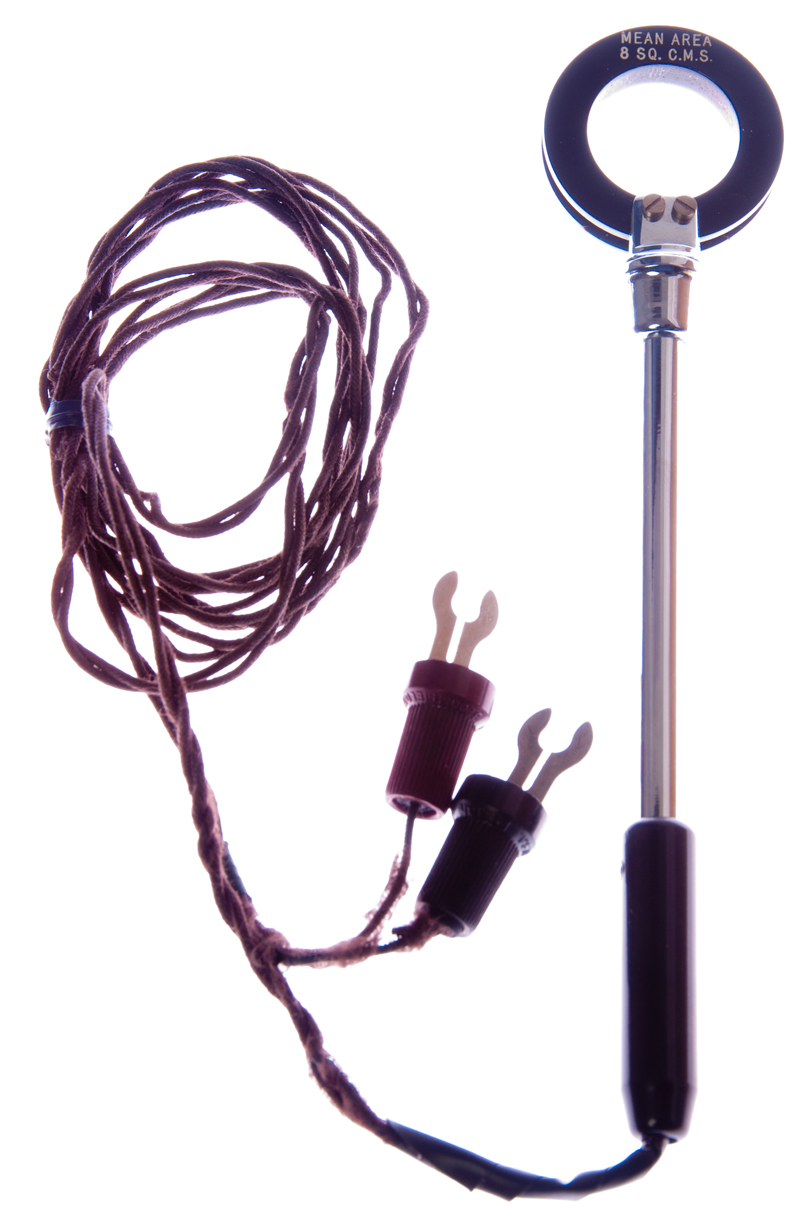
The supplied 10 turn coil has a resistance of 15.0 Ohms. So a Helmholtz coil for use with this fluxmeter would need to have a resistance of 15.0 Ohms (or maybe it should be 17.31 Ohms?)
This is a laboratory instrument for general use. The 1957 vintage Sensitive Research Instrument Co. brand flux meter is of the type know as a Grassot Fluxmeter. It's a type of Ballistic galvanometer (Wiki) where there is no spring to bring the meter needle to zero when no current is flowing. That's to say the meter integrates all the current since the last time it was zeroed.
When a wire is moved in a magnetic filed it will generate a current. The three key components are a conductor in a magnetic filed and movement and current, any one can be an output and the other two are inputs. The wire can be stationary and if the magnetic field changes a current will be generated. So a way to measure the strength of a magnet is to use it's field in a way that integrates all the flux lines. One way to do that with a cylindrical magnet where the round ends are the poles is to place a coil around the center of it's length and then pull the magnet out of the coil, that way the coil crosses the maximum number of flux lines. Another way would be to place the magnet in the center of a Helmholtz Coil on a table that can rotate and zero the integrating voltmeter, rotate the table 180 degrees and note the integrated voltage. This is the method used to measure permanent magnets that have their poles on opposite ends.
Another arrangement would be for magnets, like a horseshoe, is to place a search coil at the location of maximum filed, zero the meter then pull the coil away from the magnet.
A more modern type of fluxmeter uses an operational amplifier (Wiki) integrator (Wiki) circuit. The design needs to include problems of drift and the non ideal character of an op amp so is more complex that the simple integrator circuit.
The insulation on the search coil test leads has hardened and needs to be replaced. An Ohm meter reading is way too high, so there's an open circuit somewhere that needs to be fixed so the resistance of the probe can be measured before the repair. That way the total resistance will be the same after the repair.
2252059Method and a device for determining the magnitudes of magnetic fields, Gustav Barth, Siemens,Dec 24, 1936, 324/253, 102/427, 102/417, 340/870.33, 33/361
Called by 42 other patents.
1832128Process and apparatus for measuring magnetic field intensities, Klopsteg Paul E, Central Scientific Co, Nov 17, 1931, 324/257, 324/102, 324/103.00R- adds known flux "Apparatus including a Hibbert magnetic standard, a Duddell inductor, and a mutual inductometer, and the processes of using them, are familiar, and I make no claim to them."
The Hibbert Magnetic Standard consists of a coil would on a cylindrical brass form that can be dropped into a circular gap in a permanent magnet. The height from which the coil is dropped is fixed by a latch that holds the coil in the up position. When dropped the coil cuts the same number of magnetic lines. It's calibrated knowing the number of turns and the field strength in the gap.
The Duddell Inductor is similar to the Hibbert Magnetic Standard in that it generates a known voltage waveform. In this case fixed coils are used to generate a controllable magnetic filed and when search coils move then generate the output which is a linear function of the drive current.
A Portable Apparatus for Measuring Magnetic Fields by Reinhard Conrad Winger - 1913
From the meter face (Fig 5 above):
Important - Keep Search Coil Resistance at 15 Ohms (hand written sticker says: "17.31 Ohm, keep resistor across terminals when meter not in use."
Sensitive Research Instrument Corporation
Mount Vernon, New York
Sensitivity = 10,000 Maxwells (Wiki: Maxwell) per division when using a single turn search coil
Flux: 1 Weber = 1 Tesla * Meter^2 = 10^8 Mx = 1 Volt * Second = 1 Joule / Amp
A Fluxmeter could show any of the above units.
Flux Density: 1 Tesla = (V * s)/m^2 = Newton /(Amp * meter) = Joule/(Amp * m^2) = (Henry * Amp)/m^2 = Weber/m^2 = kg/(Coulomb*second) = (Newton * Second)/(Coulomb * meter) = kg.(Amp * second^2)
FLUX
Lines = (10,000 * Divisions Def't) / (No. of Turns in the search coil) = 1000 * Deflection for supplied coil
Gausses = (10,000 * Divisions Def't) / (No. of Turns * Mean Area of the search coil in square cms) = 125 * Deflection for supplied coil (10 Turns 8 sq cm).
Model: FM
No. 800036
DCX8 magnet
From K&J magnetics web page for DCX8 magnet
Supplementary info on DCX8:
- Dimensions: 3/4" dia. x 1 1/2" thick
- Tolerances: ±0.004" x ±0.004"
- Material: NdFeB, Grade N42
- Plating/Coating: Ni-Cu-Ni (Nickel)
- Magnetization Direction: Axial (Poles on Flat Ends)
- Weight: 2.87 oz. (81.5 g)
- Pull Force, Case 1: 37.70 lbs
- Pull Force, Case 2: 37.70 lbs
- Surface Field: 6403 Gauss
- Max Operating Temp: 176ºF (80ºC)
- Brmax: 13,200 Gauss
- BHmax: 42 MGOe
With a DC magnetometer expect to see a field strength of just above 5,000 Gauss at the surface, centered on the pole.
With a Helmholtz coil and fluxmeter, expect a measurement of around 1,300-1,400 µVs cm.Operation
Expected Sensitivity to Earth's magnetic field
The deflection for a 0.5 Gauss field would be 0.5 / 125 = 0.004 divisions
That's to say the supplied search coil will not deflect from the Earth's magnetic field.
This also means the Earth's field will have a very small effect if the box is positioned in different compass directions.
When a DCX8 magnet is placed half way in the search coil and the meter zeroed and removed the deflection is 28.
Lines = (28 * 10,000) / 10 = 28,000Gauss = (28 * 10,000) / (10 * 8) = 3,500
Note for this type of measurement the search coil should be very tight against the diameter of the permanent magnet and in this case there's a considerable air gap.
The actual reading should be higher than 3,500, maybe by the ratio of the magnet circle area to the coil ID area.
Magnet circle area: 2.85 sq cm
Coil area: 8 sq cm
3500 * (8/2.85) = 9,824 which is a little high.
If the ratio of the diameters is used:
3500 * 1.9 / 1.5957 = 4,167 still low.
The GE Gauss meter reads about 4000. Also low, but closer to the 4,167 gauss so maybe more correct?
Data from K&J:
Dimensions: 3/4" dia. x 1 1/2" thick
Tolerances: ±0.004" x ±0.004"
Material: NdFeB, Grade N42
Plating/Coating: Ni-Cu-Ni (Nickel)
Magnetization Direction: Axial (Poles on Flat Ends)
Weight: 2.87 oz. (81.5 g)
Pull Force, Case 1: 37.70 lbs
Pull Force, Case 2: 37.70 lbs
Surface Field: 6403 Gauss
Max Operating Temp: 176ºF (80ºC)
Brmax: 13,200 Gauss
BHmax: 42 MGOe
DCX8 + Sensitive Research Fluxmeter & 10T 8 sq cm probe
The supplied search coil has a constant K of 10 * 8 = 80.
Gauss = Deflection * 10,000 / K for DCX8 = 28 * 10000 /( 10 * 8) =3500 Gauss.
DCX8 + Sensitive Research Fluxmeter & Helmholtz coil
The Helmholtz coil has a resistance of 19 Ohms, a little off from the 15 Ohms desired, but probably OK.
The Helmholtz coil results in a magnetic moment (Wiki) rather than a flux.
DCX8 magnet Deflection is 11.
Br = (Magnetic permeability) * Deflection * (meter constant) / (Volume of magnet)
Br = (4 * PI E-1) * 11 * 10,000 * 1G/A / 10.859375 cm3 = 12,729 Gauss (slightly below the Brmax of 13,200 Gauss given by K&J magnetics)
Testing by installing magnet, zeroing meter (or setting to 50), rotating magnet 180 degrees & reading deflection
Br = 578.595 * deflection /(No. of magnets)
No. of DCX8 magnets
Def
Br
1
23.5
13,597
2
47
13,596
3
68
13,114
Documentation
Electrical Measurements Instruments, Catalog No. 34 - 1934
The zero adjustment can be used to set needle to -50 or +50 instead of to zero thus doubling the useful scale range (100 divisions) for a single polarity swing.
This would give higher resolution than switching up a range.
The following tests can be done:
1. Measurement of Magnetic Flux - explained above based on information printed on the meter itself.
Total Flux (cgs lines, Maxwells) = (K * D)/T2. Obtaining B-H Curves -
K = 10,000 Mx (meter constant)
D = Deflection of meter (including range switch multiplier)
T = No. of Turns in search coil.
Gauss (lines/sq cm) (Mx/sq cm) = (10,000 * Divisions Def't) / (No. of Turns * Mean Area of the search coil in square cms) = 125 * Deflection for supplied coil (10 Turns 8 sq cm).
The example to be tested should be in a well forged closed ring having a primary and a secondary winding.
Connect primary through a reversing switch and ammeter to a direct current supply.
Connect secondary coil to Fluxmeter.
Reverse the primary current about 50 times to reduce the residual magnetism in the ring.
Then close the primary circuit and read Fluxmeter.
Take a number of readings starting from a low primary current, in each case opening the primary circuit before adjusting the current controlling rheostat.
Bring Fluxmeter pointer to zero, close primary circuit and read.
It may be necessary to decrease the number of turns in the search coil so the magnetizing current is increased to prevent the Fluxmeter pointer from deflecting off scale.
Magnetizing Force H (cgs) = (N * I) / ( R * K)3.Permeability
N number of primary turns
I primary current Amps
R mean radius of \ring in cm
K 4.987
Flux Density B = ( D * Z * 0.5) / (C * S)
D deflection of Fluxmeter
Z Maxwells per division of Fluxmeter (range)
C Cross section of ring in sq cm
S Number of secondary turns
Permeability = B/H (from 2 above)4.Measurement of Flux in a Bar Magnet
Draw a suitable search coil from the neutral section of the magnet. (the coil should be very close to the magnet).5. Measurement of Horseshoe Magnet
Pole Strength = Fluxmeter Reading / 12.57 (12.57 = 4*PI)
Total Flux = (K * D) / T6. Measurement of Electrical Discharges
K = 4.987
D = Fluxmeter Deflection
T = No. of Turns in search coil
In this case the fluxmeter can be considered a calibrated coulomb meter. The discharge must take place through a low resistance, non inductive shunt having a resistance of not over 0.2 Ohm. Connect the fluxmeter across the shunt. Under the above conditions:7. Measurement of Mutual Induction
Coulombs discharged = Q = (D * 1E-4)/Rs
Rs: resistance of shunt
As our fluxmeter is a most versatile instrument it may be used to measure the coefficient of mutual induction of two coils. Connect one coil to a series circuit consisting of an ammeter, battery and reversing switch; the other coil to the fluxmeter. Close circuit and read. Reverse and read. Take the mean of readings.
Coefficient of mutual induction = K = (5 * D) / I
D = Fluxmeter deflection
I = Current in amps
Helmholtz Coil For Fluxmeter
The 12" diameter coil above has a deflection of only 11 Mx on the most sensitive range and it has 19 Ohms resistance not the 15.0 Ohms the Fluxmeter expects. While it's nice for cancelling the Earth's field where you have very fine control, it's not so good for measuring permanent magnets.
So I made a spread sheet based on using common PVC plastic pipe couplings based on 7.5 Ohms per coil so the two coils will add up to exactly 15 Ohms. This means that for a given wire size the length is fixed independent of the diameter. So you get more turns the smaller the diameter of the fitting. But the size of the coil cross section should be less than 1/10 of the diameter of the coil so for the smaller diameters there's not enough room for the needed turns so only some combinations of diameter and wire size are realizable.
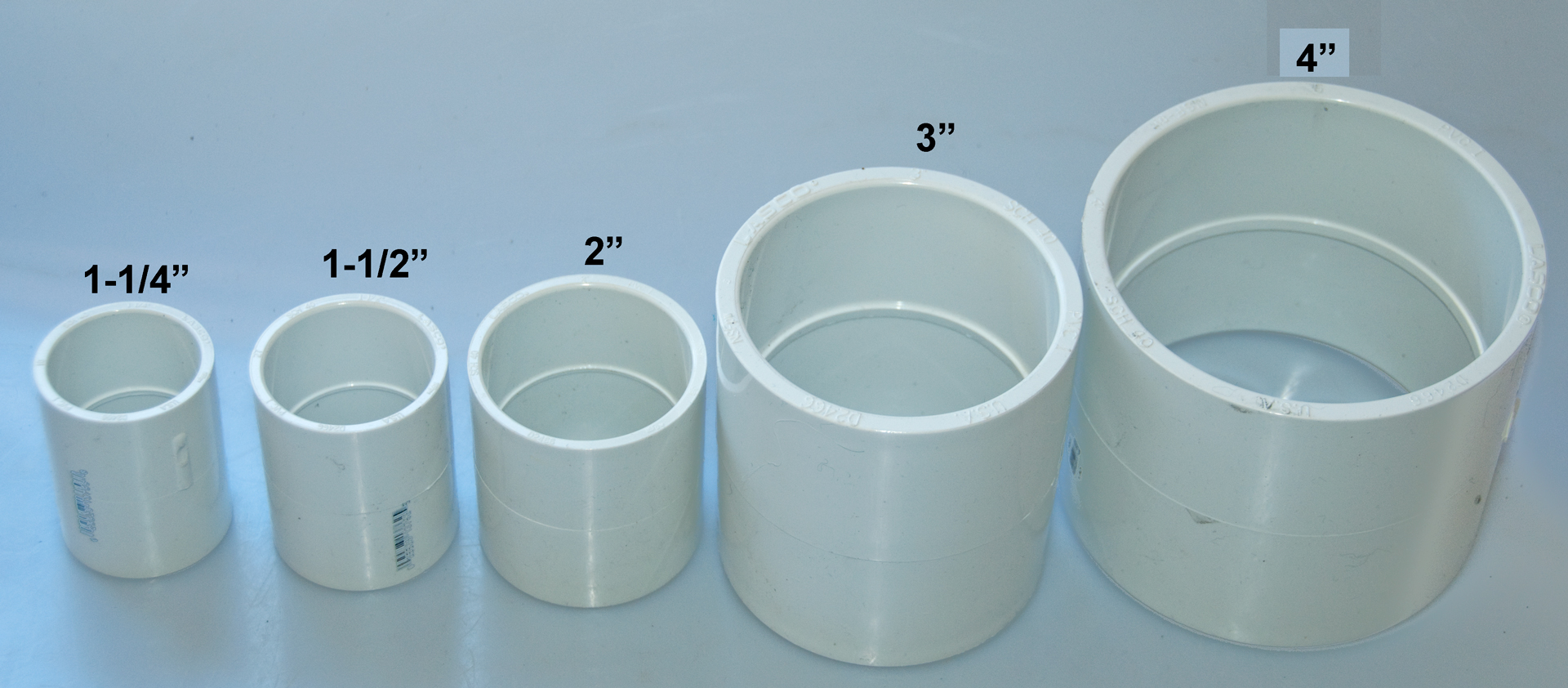
PVC Couplings
Nominal Size
OD ID Len 1-1/4"
1.967
1.662
2.620
1-1/2"
2.220
1.900
2.744
2"
2.715
2.380
2.852
3"
4.032
3.504
4.211
4"
5.023
4.540
4.268
Using couplings with diameters of: 1-1/4, 1-1/2, 2, 3 and 4" nominal sizes the highest Gauss per amp I found considering using 18, 24 and 32 AWG magnet wire was with the 3" coupling.
277 turns per coil gives 7.5 Ohms and 243 Gauss/Amp. Next need to figure out the turns/row and the odd number of rows. Ideally the Width (0.0213" * Turns/row) would be 0.982 * the height (# of rows * 0.0213"), but we'll see.
For 17 rows (odd number means enter on left exit on right) where each row has 16 turns there are 272 turns (close to the design of 277 turns and lower not higher).
The aspect ratio is 16/17 = 0.94 which is near 0.982.
The resistance will be low by 5 + 5 = 10 turns which is 0.270 Ohms. This can be made up using using some combination of test lead length and wire size.
Note for symmetry the cross section of a coil should be the same top to bottom and left to right so it's not a good idea to use a turns per row - number of row combination that has too many total turns since removing turns would make the cross section asymmetrical.
It may be the case that using a different wire size (maybe 26 or 28 AWG would allow getting enough turns on the next smaller diameter (2-1/2" coupling) and so get a higher Gauss/Amp value. Since I have 24 awg in stock that's what I'll use on the 3" coupler.
Now how to form two slots for the wire. One way is to use an adjustable circle cutter where there are two bits on the bar rather than the single bit type which is not as stable.
1/8" plywood is available and the mill will cut it into 6" squares and I can use a drill press to cut holes in the center. Four of these can be slipped onto the 3" PVC coupling and using some blocks of wood cut to the width of the desired gap ( 16 * 0.0213 = 0.340") the two pieces of plywood can be cemented (glued?) to the coupling at one end. A similar thing is done at the other end where the side to side distance (same as the center to center distance) between the two coils is set at 2.016".
12 May 2015 - cuter on order along with a Talley counter for keeping track of how many turns. Another way would be to pre cut the wire length, but it's awkward to handle almost 300 feet of wire. Better still is to mark the inside edges of the plywood for the height (0.340") and remember that the wire starts on the left and finishes on the right.


Annis M25 Pocket Magnetometer

R.B. Annis Instruments makes different versions of this magnetometer and this one is for the Earth's field and so has -0.5 to 0 to +0.5 Gauss range.
The M25 full scale ranges are: 0.5, 1, 2, 5, 10, 20, 50 & 100 Gauss.
YouTube - Automatic Helmholtz Calibration System part 1 (for calibrating pocket magnetometers)
The M25H full scale ranges are: 200, 300 & 400 Gauss.
Cenco Scientific 79860 Dynamo Analysis Apparatus
In the 1929 catalog a prior version of this device was catalog No. F3691.
It is designed to be used in conjunction with a ballistic galvanometer (see above) aka Fluxmeter so I'm putting it on this web page.
Fig 41
Fig 42
The wheel is divided into 36 segments each of 10 degrees. The escapement (Wiki) allows the wheel to rotate 10 degrees for each operation to the top lever. The pawl on the right is manually lowered and it's spring puts force on the wheel to cause counter clockwise rotation.
The 6 horseshoe magnets look like they came from a magneto telephone ring generator. They are about 5-1/2" long and there's about a 2" gap between the poles.
A DC magnetometer measures about 50 mT (500 Gauss) in the region where the coil turns.
Problems
There was a very small spring that should have caused the pawl to stay in contact with the wheel making it easy to rotate the lever clockwise to tension the wheel, but the spring was either installed improperly or was broken. In any case when I removed the pawl, spring and holding pin the spring was lost. So the operation now is as received where you need to manually press the pawl onto the wheel so that it catches properly.
The DC resistance between the two Banana jacks initially measured at infinity. After operating the wheel for a turn or two the resistance has come down to about 345 Ohms, but measuring the resistance at the two solid commutator rings shows more like 43 Ohms. The rings have a coat of oxide that needs to be polished and I expect the place where the metal brushes touch the rings also needs to be cleaned and polished.
The coil resistance of 34 Ohms is about twice the required resistance of 15.0 Ohms that the ballistic galvanometric wants to see. It may be that a shunt resistor can be used to correct that?
I checked the polarity of the magnets using the AMY6 checker and the polarity matches the markings stamped into the magnets.
A DC Gaussmeter shows the filed where the coil turns it be about 50 mT (500 Gauss). I don't know if the magnets have lost their charge of if that's about correct.
The book A Short University Course in Electricity, Sound and Light by Robert Millikan & John Mills, 1908 (free Google book) shows an earlier version of this device in paragraph 88 Experimental Analysis of Dynamo Induction and uses it in a experiment 12 at the end of the chapter where Fig 105 shows the sine wave with data that peaks at 22.5 mm deflection (it seems that their ballistic galvanometer was not calibrated like the above Flux meter).
By using Brasso and a Q-Tip and rubbing both rings for awhile then turning the wheel 180 degrees and repeating the procedure a couple of times the resistance between the banana jacks went down to about 35 Ohms with the liquid still there. Then, after cleaning off the rings the resistance stayed low.


Related
AlphaLabs Model 1 DC Gaussmeter & GE Gauss meter
F.W. Bell 640 Incremental Gaussmeter
Walker Scientific MG-3D Gaussmeter
DC Permanent Magnet Motors
Home Built Magnetometers
Sensors, Magnetic
Magnets
Aircraft Pilot's Standby Magnetic Compass
Electromagnetic Toy Engine
Flux-gateMagnetometer Patents
Gilbert DC 3-pole Electro-magnetic Machine
Helmholtz Acoustic Resonator & Tuning Forks
MC1 Magnetic Compass Calibration Set similar to AN/ASM-344
Leclanché Battery - wet battery
MESCO 1011 Toy Engine
No. 6 Dry Cell -
phones Telephone Equipment - TelPat Telephone Patents
StkTckPat Stock Ticker Patents
Telegraph - TelPat Telephone Patents
Toy Motor Kit & modern version as well as Science First demonstartion motor
Weeden-El-Mtr DC Electro-magnetic Machine (Motor or Generator)
References
Ref 1. Magnet Testing With Fluxmeters, Helmholtz Coils and Search Coils, 6:24 - Helmholtz coil: 3X diameter of magnet & coil height = coil radius.
Links
Oersted Technology - A Method of Calibrating Helmholtz Coils for the Measurement of Permanent Magnets - About Magnetizing Magnets - 480 Fluxmeter -
Magnet-Physik
How to make the simplest magnetometer (or Gauss meter) Really a Fluxmeter- Lu Le Laboratory - Lu Le Laboratory - 84 turn solenoid coil driving Integrating Op Amp
LakeShore - 480 Fluxmeter - downloads: Helmholtz coils
Helmholtz Coils - (Turns, Amps, Meters -> Tesla)
K&J Magnetics - permanent magnets
CERN - Manufacturing and calibration of search coils -
Transformers and coils - with magnetic cores
Saturation curves for soft magnetic materials - soft Iron is 2.13 Tesla
PRC68, Alphanumeric Index of Web pages, Contact, Products for Sale
Web page created 13 April 2015