HP 5004 Signature Analyzer
© Brooke Clarke 2005 - 2007
Background
Using analog test instruments like
voltmeters or scopes to test digital circuits is less than
satisfactory. The digital signature test is a way to truble shoot
digital circuits. To do this a good working circuit needs to be
characterized for the signature at a number of test points. The
inputs to the signature analyzer are a clock, start and stop pulses and
the serial data stream on the pin under test.
This allows troubleshooting to the component level. Most
manufacturers today support troubleshooting to the board level rather
than to the component level and so you can get an HP 5004 for little
money. It's only useful if you have equipment with signature
analysis data like the
Austron 2100T
LORAN-C Timing Receiver.
Using
The 4 display characters have 16 values
but are not the common hexidecimal characters of 0123456789ABCDE, but
are instead 0123456789ACFHPU. The manual says the nonstandard
characters are so that B and D can be different (but if the number 6
has a bar on top then it's different from the letter b, and a lower
case letter d is different from all the other characters). Note
that a possible output is HP5A which looks like HPSA or Hewlett Packard
Signature Analyzer. There probably was some demo device that
caused this signature to appear.

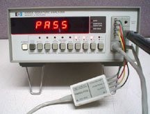
Shown
at left connected to the
Austron 2100T
LORAN-C Timing Receiver MPU PCB.
There are two cables connected to the front panel. One has the
interface module which in turn has 4 leads ending with IC pin grabbers:
Black wire Ground
Yellow wire Clock
Green wire Start
Red wire Stop
Self Test
The IC grabbers can be unplugged from the colored wires and the wires
can be plugged into the Start, Stop and Clock jacks on the front panel
of the 5004. Now with "Self Test" pressed in and the Start and
Stop buttons pressed in (negative edge) (clock does not matter) the
when the probe is inserted into the "Probe Test" jack the display will
show UP73 then ACA2. With the Start and Stop buttons out the
display is 3951 then 2P61.
The other cable goes to what looks like the 545A Logic Probe. It
has a
"reset" button and at the tip there's a translucent red plastic
sleeve and inside a red LED. Touching the tip to ground
causes the LED to turn off. Leave the tip in air or on a
tri-stated output and the LED is
medium bright and steady. Connecting the tip to Vcc causes the
LED to be on bright and steady. Connecting to any pulse train
causes the LED to blink. This is itself a great trouble shooting
tool.
I think the 5004 is computing something like a Cyclic Redundancy Check
sum from
the start signal to the stop signal. If the probe is grounded to
connected to the start pin it reads "0000". I connected to the
Vcc pin it will read some value dependent on how many clock cycles are
between start and stop.
It is a 16 bit CRC with taps at 1, 7, 9, 12 and 16.
The Austron Troubleshooting data includes where to connect the clock,
start and stop probes as well as the polarity for the clock, start and
stop signals. To be sure you have those correct there are
signatures for ground (0000) and Vcc (depends on the board).
I got the best results by pressing "HOLD" and using the "Reset" button
on the probe. The reset button needs to be pressed each
time a new test point is probed. Sometimes the reset button
needed to be pressed two times.
5006A
The 5006A is a newer version that has some more buttons and works up to
25 Mhz.
Patents
3976864
apparatus and method for testing digital circuits August 24, 1976
714/737; 714/45
4224534 Tri-state signal conditioning method and circuit September
23, 1980 327/184; 326/60; 327/76; 327/205; 327/216
4991175 Signature analysis February 5, 1991 714/732; 714/37; 714/71
5121397 Method and apparatus for producing order independent
signatures for error detection June 9, 1992 714/808; 714/800; 714/807
5301156 Configurable self-test for embedded RAMs April 5, 1994
365/201; 714/730; 714/732; 714/733
Back to Brooke's Products for Sale, Test Equipment, Microwave
Test Equipment, Time & Frequency,
Electronics, Navigation,
Position & Orientation, Military
Information, Home
This is the [an error occurred while processing this directive] time
this page has been accessed since since 21 Feb 2005.
 Shown
at left connected to the Austron 2100T
LORAN-C Timing Receiver MPU PCB.
Shown
at left connected to the Austron 2100T
LORAN-C Timing Receiver MPU PCB.