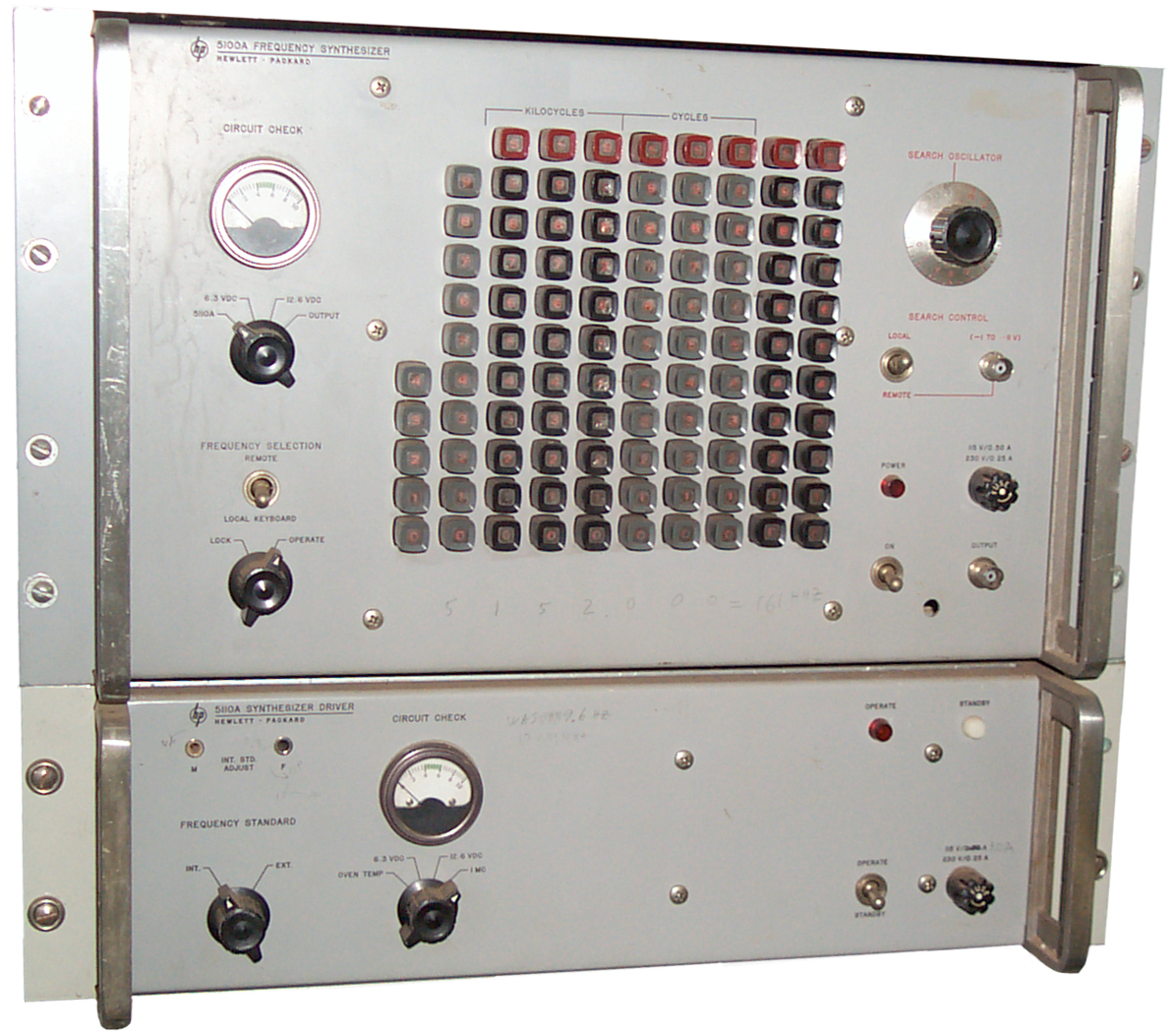
This is a synthesizer based on add,
subtract, multiply NOT on PLL methods. It is big and heavy,
but has very fast coherent switching and good phase noise.
This model was used by BR communications to develop their
chirp sounder . For remote control
on the back there is a wire for each of the buttons on the front.
That's a lot of wires!
HP Memory Project:
The
First Commercial Application of Frequency Synthesis -
HP
Journal May 1964: A 0-50 Mc Frequency Synthesizer with
Excellent Stability, Fast Switching, and Fine Resolution
App Note
96: Frequency Synthesizers Jan 1969
HP
Catalog 1965 (pdf pg 95) - "Synthesizer design and
construction make possible output signals whose spurious content
is 90 db or more below the selected frequency. Signal-to-noise
ratio in a 3 kc band centered on the selected signal is more than
60 db. Particular care in Model 5100A-5110A design results in a
very clean output signal over the full 50 mc range. The high order
of spectral purity permits accurate doppler measurements,
microwave spectroscopy, narrow-band telemetry, stable local
oscillator for a transmitter and/or receiver, automatic testing of
crystal filter response and many other applications."
The 5100A A1A4 assembly takes in 1
MHz and after amplifying the signal with Q1 drives Step Recovery
Diode CR6. In order to get the diode to deliver more output
power it has been built into an assembly (E1) consisting of the
SRD, a heater and a temperature sensor. Q2 drives the
heater. Running the Step Recovery Diode hot increases its
electrical lifetime and hence the output. Running
electronic components hot causes their physical lifetime to be
shortened and in this case the SRD failed. When that happens
the 10 outputs die and the whole 5100 Synthesizer no longer works.

|
|
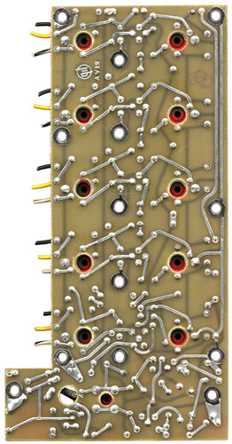
Comp
side of A1A4 PCB
|
Trace
Side Optically Flipped
|
The A1A4 Printed Circuit Board holds the Step Recovery Diode in
the lower right (off white circle).
One fix is to find a stud mount Varactor diode and wire it in
place of the SRD and leave the heater disconnected.
Another possible fix is to use the
circuit from
the PRC-25 A15 / PRC-77 A45 module. This module has a
1 MHz crystal oscillator and using a one transistor circuit
generates a lot of harmonics. In the PRC-25 the transistor
is a PNP 2N2273 and in the newer PRC-77 it's an NPN
2N918. A 10 pF capacitor (typo in the PRC-77 manual) feeds
the 1 MHz signal to the base. The base has a 10k resistor to
ground. The emitter has a parallel circuit consisting of a
1k2 resistor and a 0.05 uF cap to ground. The collector is
transformer coupled to the output with the top of the transformer
primary connected to +9.5 volts and decoupled to ground with 0.05
uF. Positive supply isolating by means of a 200 uH
choke. The transistor is off during the negative input half
cycle and turns on only during the positive half cycle generating
a narrow pulse rich in harmonics. The output of the module
consists of harmonics at 1 to 12 Mhz and so is not directly
suitable for use in the 5110 which puts out 30 to 40 MHz.