In the early days of radio the loose
coupler was commonly used to couple the antenna and ground system to
the input to the receiver. The early receivers used crude devices
to rectify the radio frequency signal. These rectifiers had
impedance that varied a lot so some means of
impedance transformation was needed.
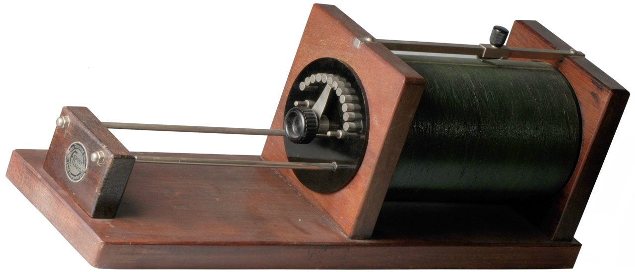
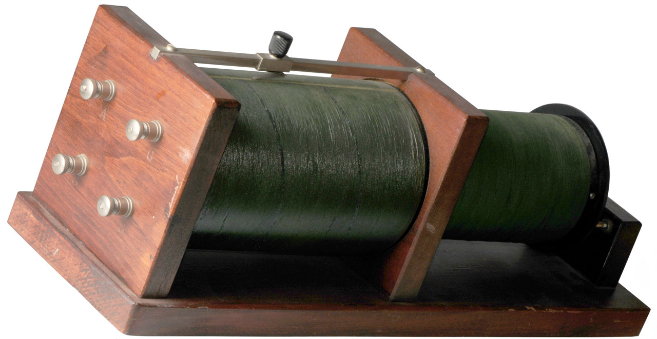
The loose coupler is made up of two parts. The primary coil is
fixed to the frame and has a slider to vary it's
inductance. The secondary coil is
mounted on two rods that are also electrical contacts. The
secondary coil can be moved relative to the primary coil changing the
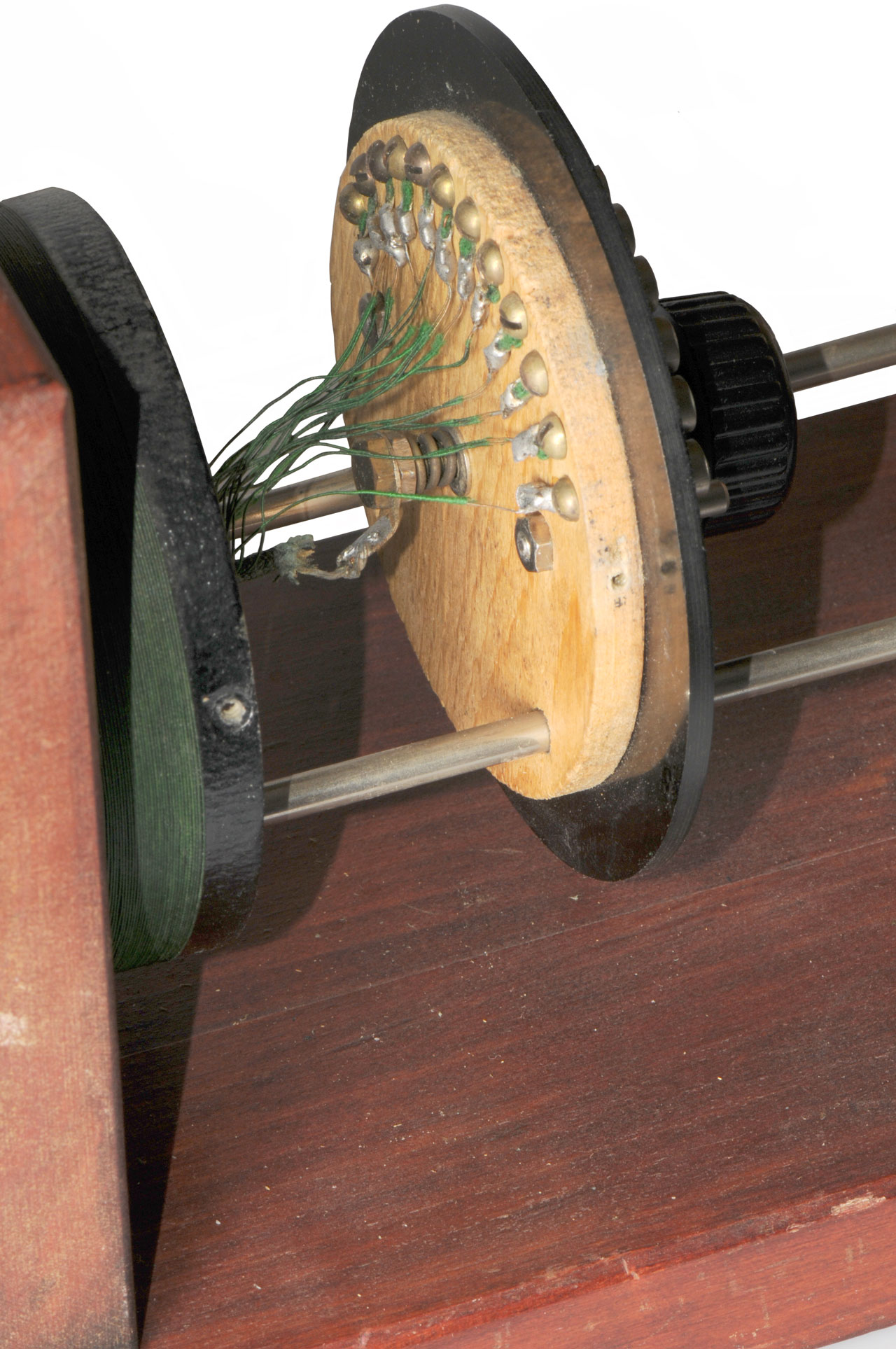
coupling. The secondary coil also is tapped and the twelve
position switch on the end of the secondary coil selects the tap
allowing it's inductance to be varied.
The upper left terminal is marked A (Antenna) and the one to its right
G (Ground).
The two lower left and right terminals are marked S (Secondary).
The A terminal goes to the end of the primary close to the
terminal. The G terminal goes to the slider above the primary.
The two S terminals go to the secondary support rods, but there doesn't
seem to be a sliding contact, rather there are also wires connected to
these terminals.
The right side S terminal is connected to the switch wiper. I
think the other S terminal is connected to the end of the secondary
coil that's closest to the terminal.
719005
Tuning Device for Wireless Telegraphy, W.S. Hogg, Jan 27 1903, -
334/65 ; 116/241; 334/82;
334/86; 336/119; 336/129; 336/144; 336/208; 336/223; 336/45; 336/65;
336/69; 361/296
848676
Electric Transformer, J. Murgas, Apr 2 1907, -
336/116 ; 336/129; 336/192;
336/207; 336/223
877451
Means for Receiving Intelligence Communicated by Electric Waves, G.W.
Pcikford, Jan 21 1908, -
329/347
RE13798
Means for Receiving Intelligence Communicated by Electric Wave, G.W.
Pickard Sep 8 1914 -
329/347 ; 257/41; 403/24; 439/8
Crystal Detector
836531
Means for Receiving Intelligence Communicated by Electric Wave,
G.W. Pickard
926934
Wireless Telegraph Tuning Device, L. De Forest, Jul 6 1909, -
343/850 ; 334/69; 336/116;
336/129; 336/146; 336/149; 336/206; 336/207; 336/69
1042855
Interference Preventer for Wireless Telegraph Circuits, W.L. Walker,
Oct 29 1912,
336/116 ; 336/129; 336/208; 336/45 -
Combines a loose coupler that looks
similar to the one on this page with other receiver circuitry
1043272
Tuning Device for Wireless Telegraphy and Telephony, W.E.D. Stokes
& G.W. Davis, Nov 5 1912,
336/116 ; 191/12R; 334/72;
336/129; 336/146; 336/208-
adds a rack and pinion below secondary coil to control coupling
1058555
Receiving Transformer for Wireless Telegraph Systems, E.L. Colby, Apr 8
1913,
336/116 ; 334/72; 336/129 -
secondary moves inside dual primary
1121479
Transformer, E.L. Colby, Dec 15 1914,
336/116 336/116 -
series
and/or
parallel
switching
1133441
Inductance Device for Wireless Electrical Signaling, C.O. Lorenz, Mar
30 1915,
336/116 ; 336/129; 336/231 - Conical coils
1497411
Transformer, J.C. Snell, Jun 10 1924,
336/45 ; 336/116;
336/129; 336/150; 74/502 - Concentric front panel knobs
1525563
Coil Mounting, L.J. Baker, Feb 10 1925,
336/129 ; 336/199 -
Tripple wig-wag coils behind front panel
1528686
Tuning Unit of Radiophone Apparatus, J. Neumann, Mar 3 1925,
336/129
; 336/116 - Loose Coupler behind front panel
1581366
Inductance Coil Control, G.A. Turner, Apr 10 1926,
336/129 -
Tripple
wig-wag
coils
behind
front
panel
[an error occurred while processing this directive] Page created 25 Jan
2011.