Megger
© Brooke Clarke 2014 - 2022 |
 |
 |
 |
 |
|
|
|
|
|
When testing high resistance values and using a very sensitive meter the test voltage needs to be high in order to get to 1,000 Meg Ohms (1 Gig Ohm) so the Meg Ohm Meter, Megger for short, was developed. The test voltage is regulated at about 500 Volts and the max resistance is 1,000 Meg Ohms so this is a 2 M Ohm per Volt meter.
Megger.com: The Man Behind the Insulation Tester. -
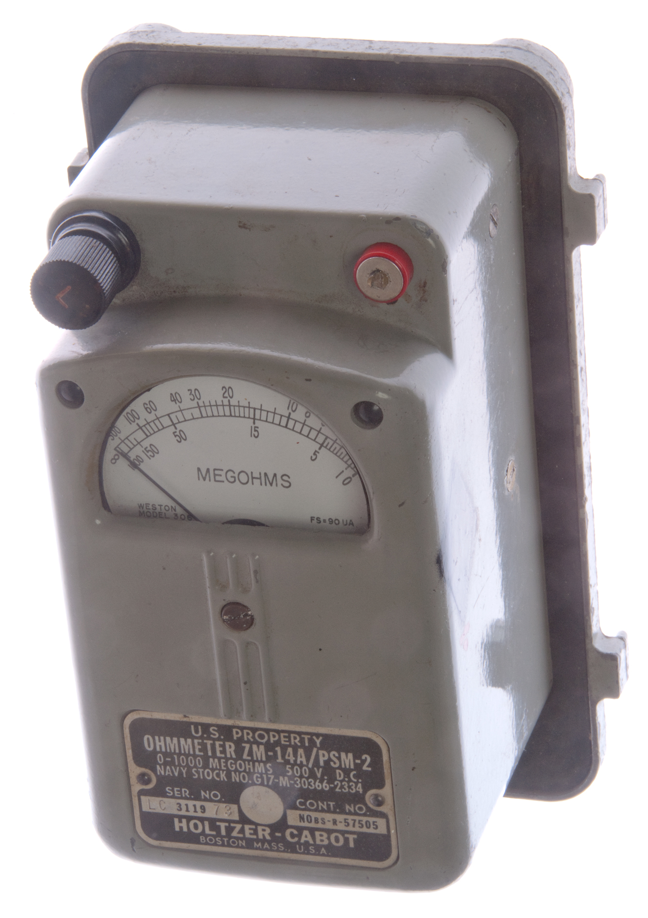
Holtzer-Cabot ZM-14A/PSM-2
I got a very good deal on this ZM-14A/PSM-2 because one of the high voltage terminals has been broken and when someone tried to repair it they broke
Navy Stock No. G17-M-30366-2334
Ser. No. LC 3119 73 Cont. No. NObs-R-57505
Holtzer-Cabot
Boston, Mass. U.S.A.
Holtzer-Cabot manufactured many products that depended on electromagnetism such as AC and DC motors (like the one used in the Western Union 5A Stock Ticker) as well as AC and Dc generators both with shaft drive and hand crank types like used in very early wooden magneto wall phones. This Megger contains a generator with a horseshoe magnet and that magnet is cylindrical and about 3/4" diameter, so this generator is different from those used in the TA-312 military field phone.
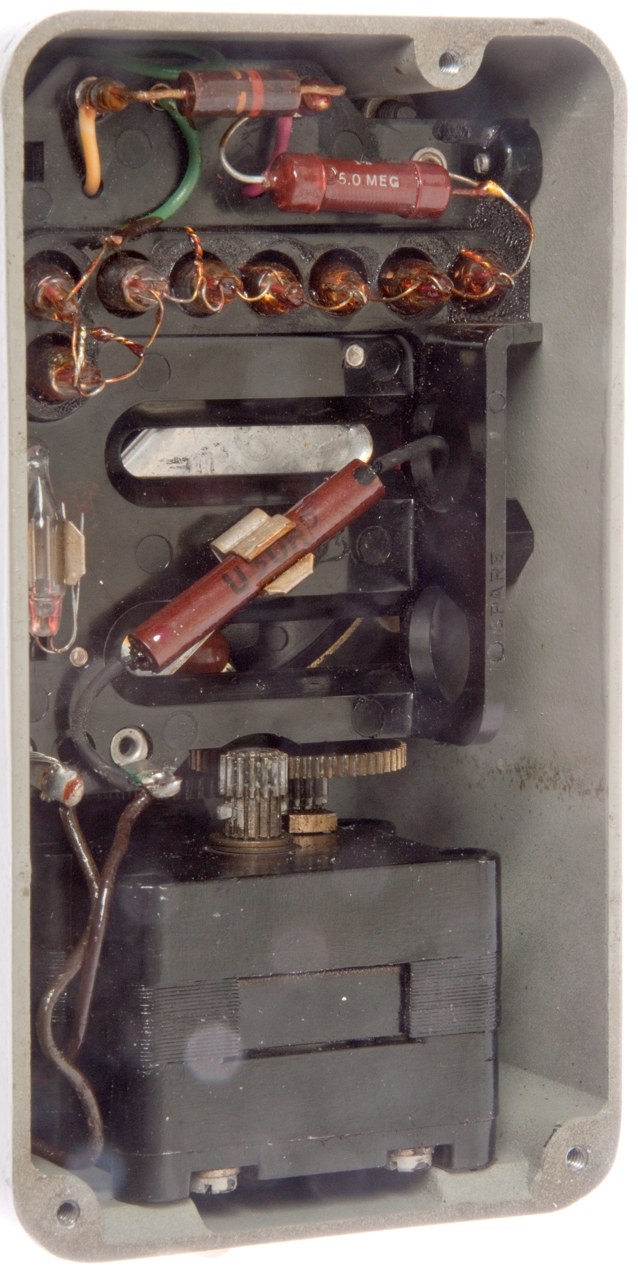
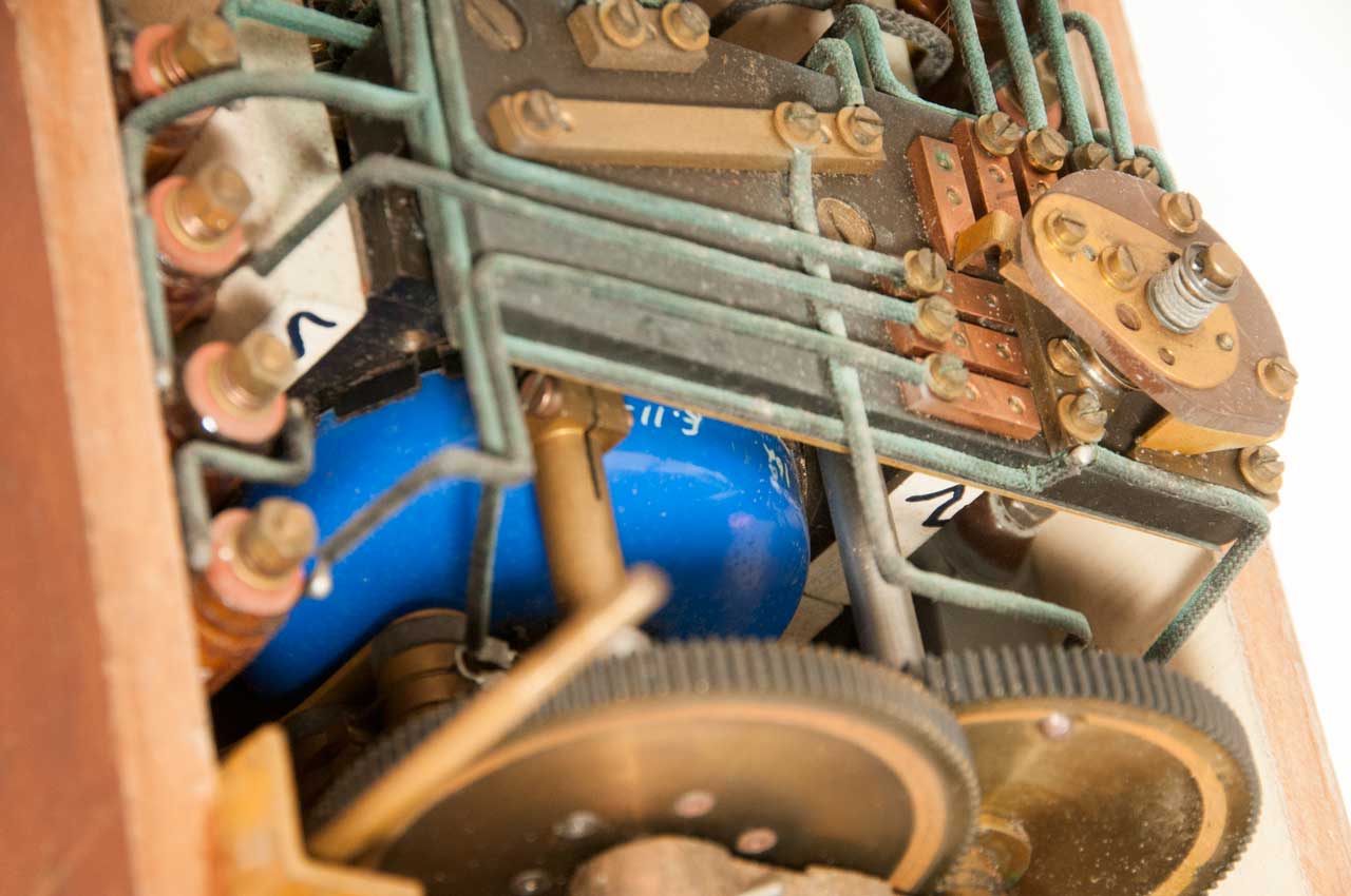
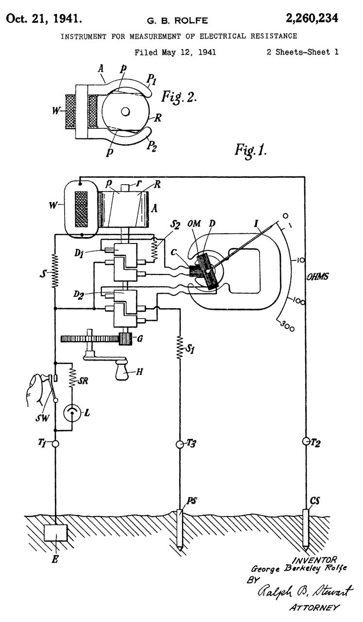
Photo taken after adding comments to the patent drawing.
Note red horizontal resistor 5.0 MEG just as was computed.
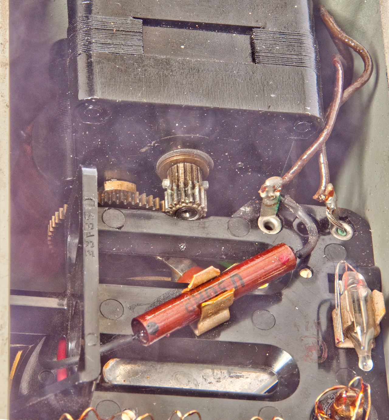
Rectifier is marked: U 30RP (maybe wrong) Let me know
To the left of the magneto you can see part of the round horseshoe
electromagnet.
Holtzer-Cabot Patents
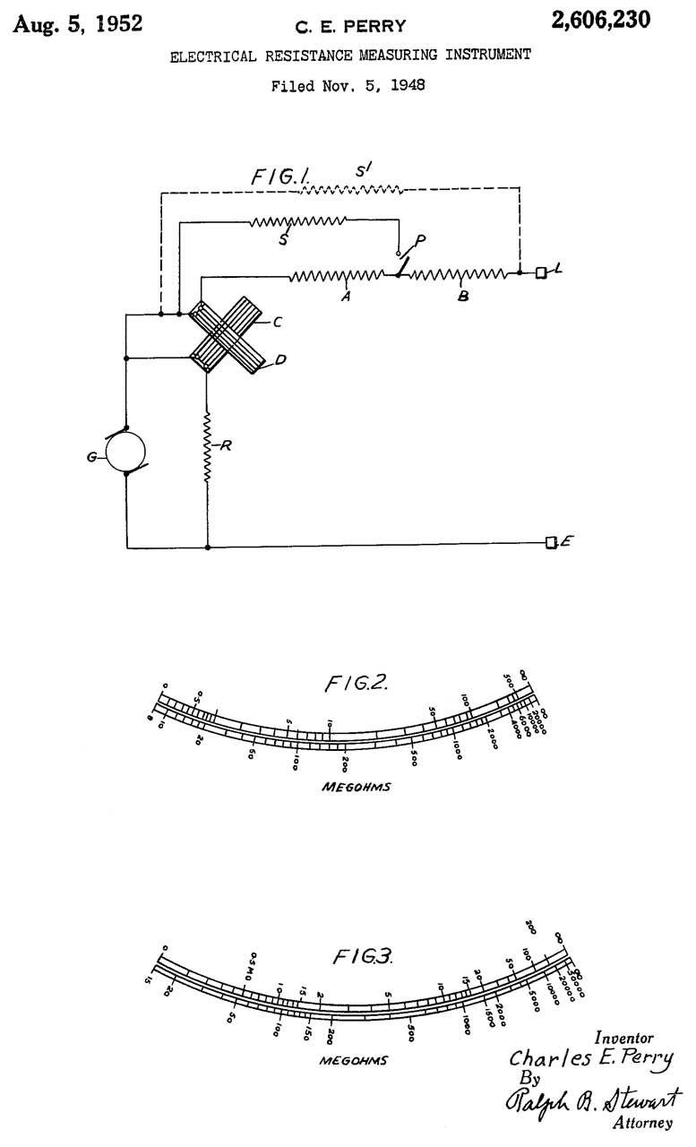
2606230 Electrical resistance measuring instrument, Charles E Perry, Evershed and Vignoles Ltd, 1952-08-05, 324/722; 324/140R; 324/704 - using two different windings on the generator (and the angle between them) the high and low ranges can be made more useful.
also see below for more
Biddle
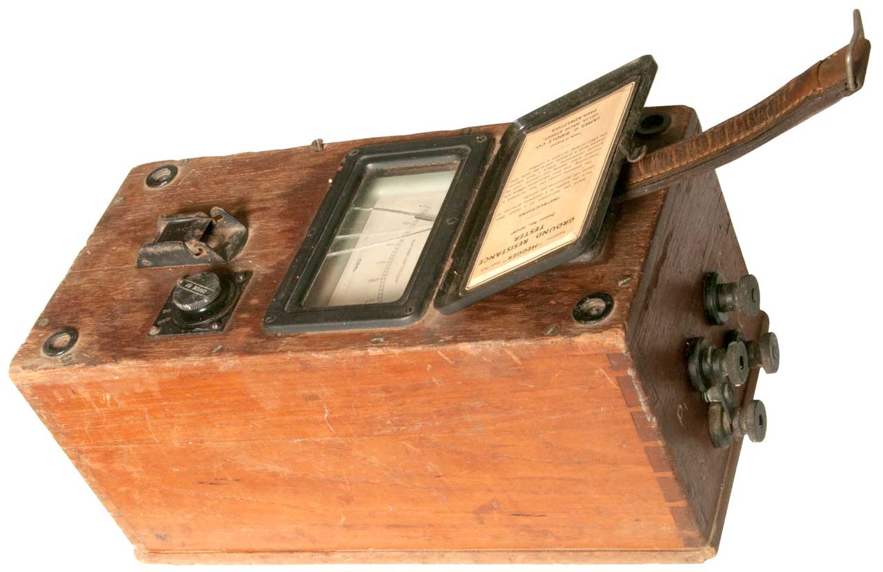
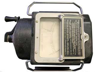
This is the classic "Megger" tester. This is probably the first model made.
Fig 1
ID Plate:
Registered Trade Mark
GROUND
RESISTANCE TESTER
Patent No. 1616387No. 715497 3ooo Ohms
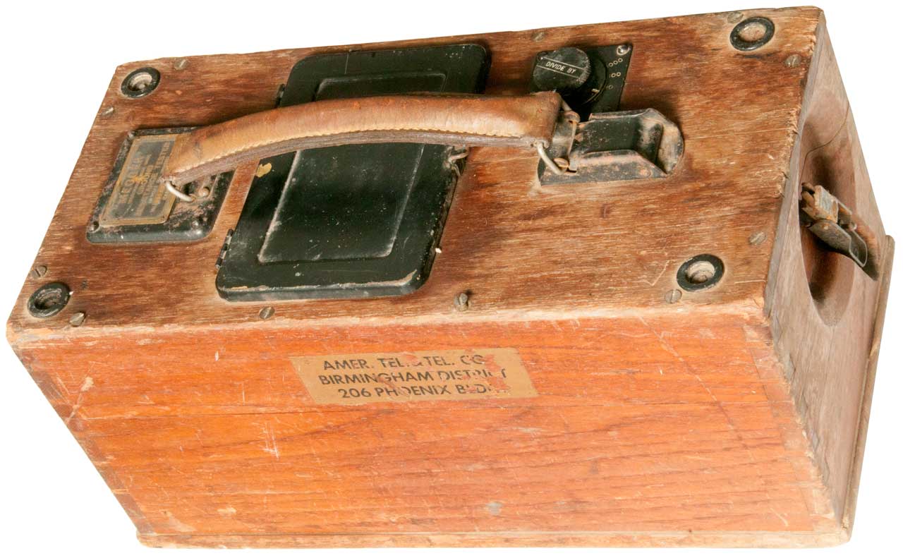
Made in EnglandSticker on side:
Amer. Tel. Tel. Co.
Birhamingham District
206 Phoenix Bldg.
Divide by: (nothing), 10, 100, 1000
Fig 2
Under meter lid:
Ground Resistance
Tester
Patent No. 1616387
________
Instructions
Stand the instrument on a steady base.
Turn handle in a clockwise direction at
about 135 revolutions per minute.
The potential axross the Test Terminals is
Alternating, and thus electrolytic effects are
avoided when testing any circuits, such as
ground connections, where a back electro-
motive force is present, and at the same time
the effedt of stray currents is nullified.
_______
Made in England
James G. Biddle Co.
1211-13 Arch Street,
Philadelphia.
E. GRT 188 W.P. 250-10-40
Terminals labeled:
P1 P2
C1 C2
Fig 3
There are 4 fasteners in the corners of the top.
I flooded each cavity with Kroil.
One of them has a normal slotted head screw,
so I removed it and noticed that it was the
correct length to reach the part line.
Did not have special tool to remove the 3 others,
so used a small flat blade screwdriver as chisel
and lightly tapped it with handle of larger screwdriver.
Then just used small screw driver to remove them.
Note lid is rotated 180 degrees from correct position.
Fig 4
Fig 5
The blue circular device is the armature. In Fig 3 above you
can see wires going from the commutator to the blue device.
The gray bars are magnets I marked S (left) and N (right).
Did Biddle buy the armature/generator from a vendor? Let me know.
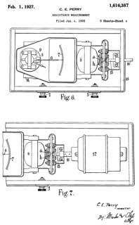
Fig 6
Blue armature marked: 12/46 RES 16k maybe a s/n: E115120
Biddle Patent
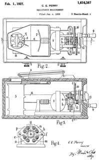
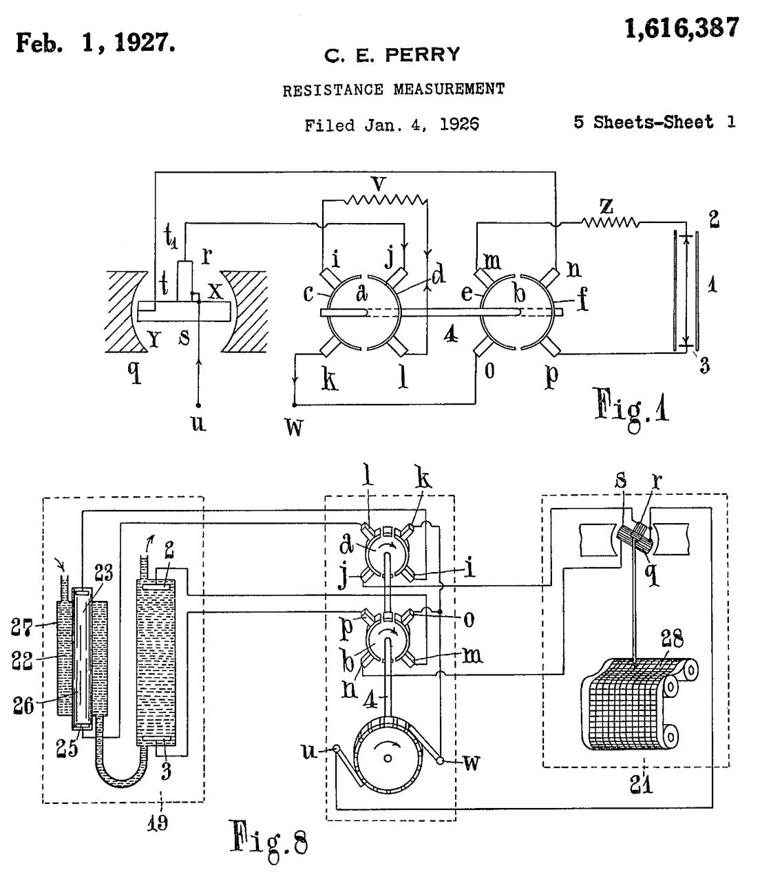
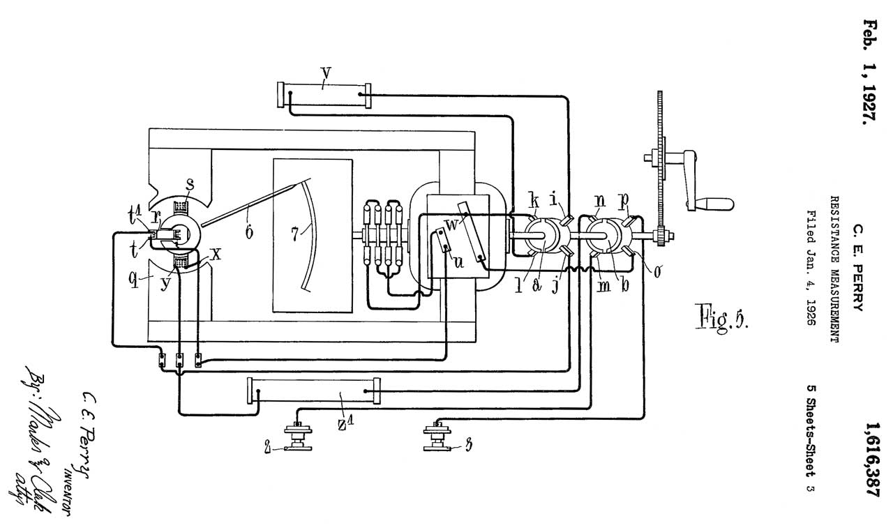
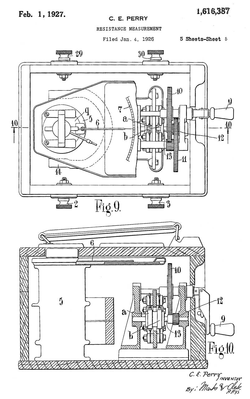
1616387 Resistance measurement, Perry Charles Edwin, Evershed and Vignoles Ltd, 1927-02-01, 324/439; 324/443; 374/17 -
patent number on wood box on eBay so I got it.
(8) - armature surrounded by magnet bars (14)
(Fig 7) option for motor drive instead of hand crank.

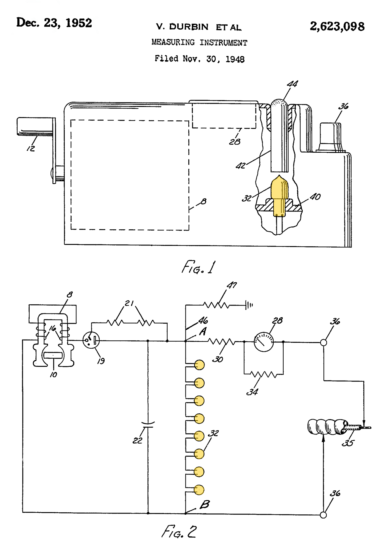
2623098Measuring instrument, Johnson Ernest W, Vernon Durbin (National Pneumatic Co.) Dec 23, 1952 - 324/722 ; 322/46; 322/96; 340/642
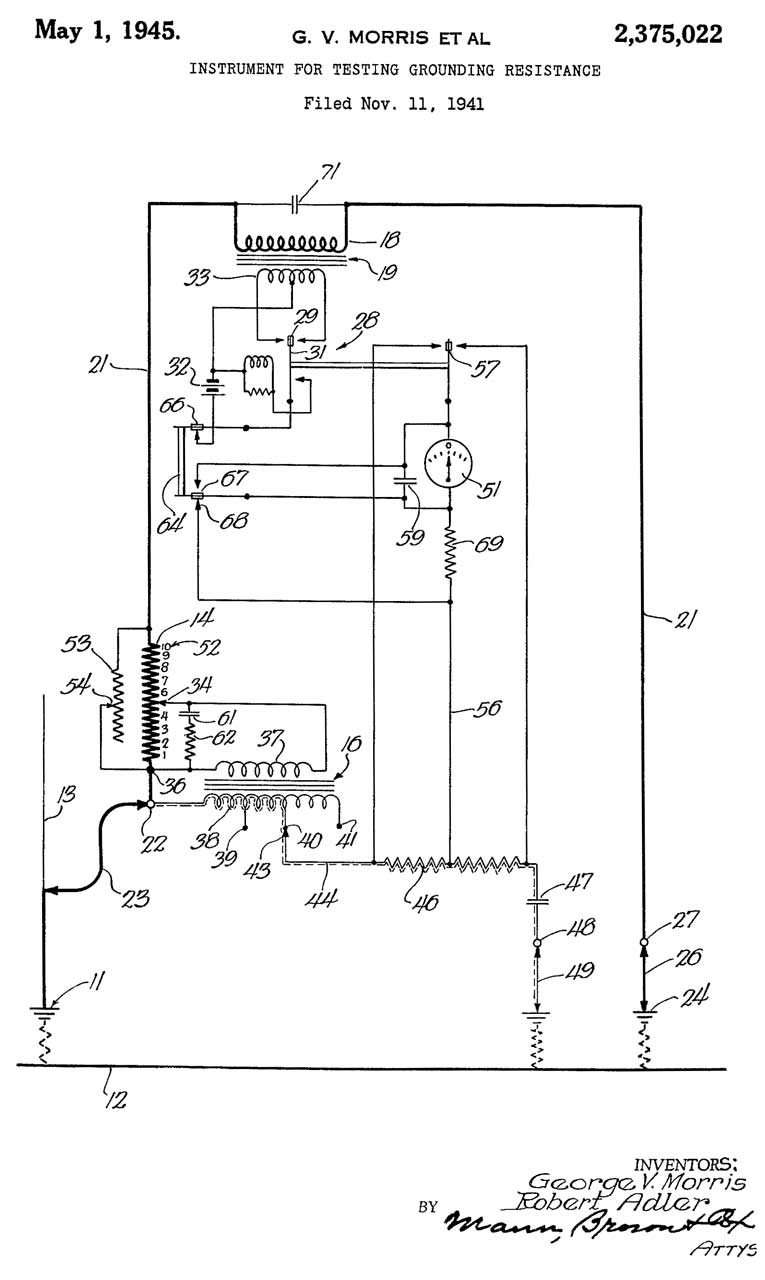
Neon lamps are used to regulate the output DC voltage, unlike the Biddle that uses a mechanical governor on the magneto.
The light from the Neon lamps is visible at the top so that the operator knows to crank fast enough to keep them lit.
Voltage from A to B (across filter cap (22) is about 500 Volts DC.
8: magneto
12: hand crank
19: HV rectifier
21: no longer used bias resistor for vacuum rectifier
22: filter cap (points A and B are across this cap)
28: Weston 306 90 uA meter movement
The calibration resistor (34) may be to bring the parallel combination to 100 uA full scale).
30: short current current limiting resistor
If the calibrated meter/R34 combination is 100 uA fs then this resistor would be 5 M Ohms.
Then half scale would be 25 M Ohms.
32: String of Neon lamps
34: Meter calibration shunt
36: Test Terminals
42 plastic rod light pipe with ends (44) rounded and frosted
47: guard resistor for leakage paths between terminals (36) and case
Calls:
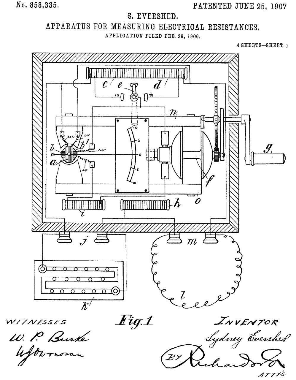
858335 Apparatus for measuring electrical resistances,Sydney Evershed ( Evershed Vignoles Ltd, Sydney Evershed), Jun 25, 1907, 324/706 - contains geared up AC generator
Used for troubleshooting telegraph lines in addition to High Resistance testing. Similar to ZM-4 Bridge.
1616387 Resistance measurement, Perry Charles Edwin, Evershed and Vignoles Ltd, 1927-02-01, 324/439; 324/443; 374/17 - on wood box eBay Biddle
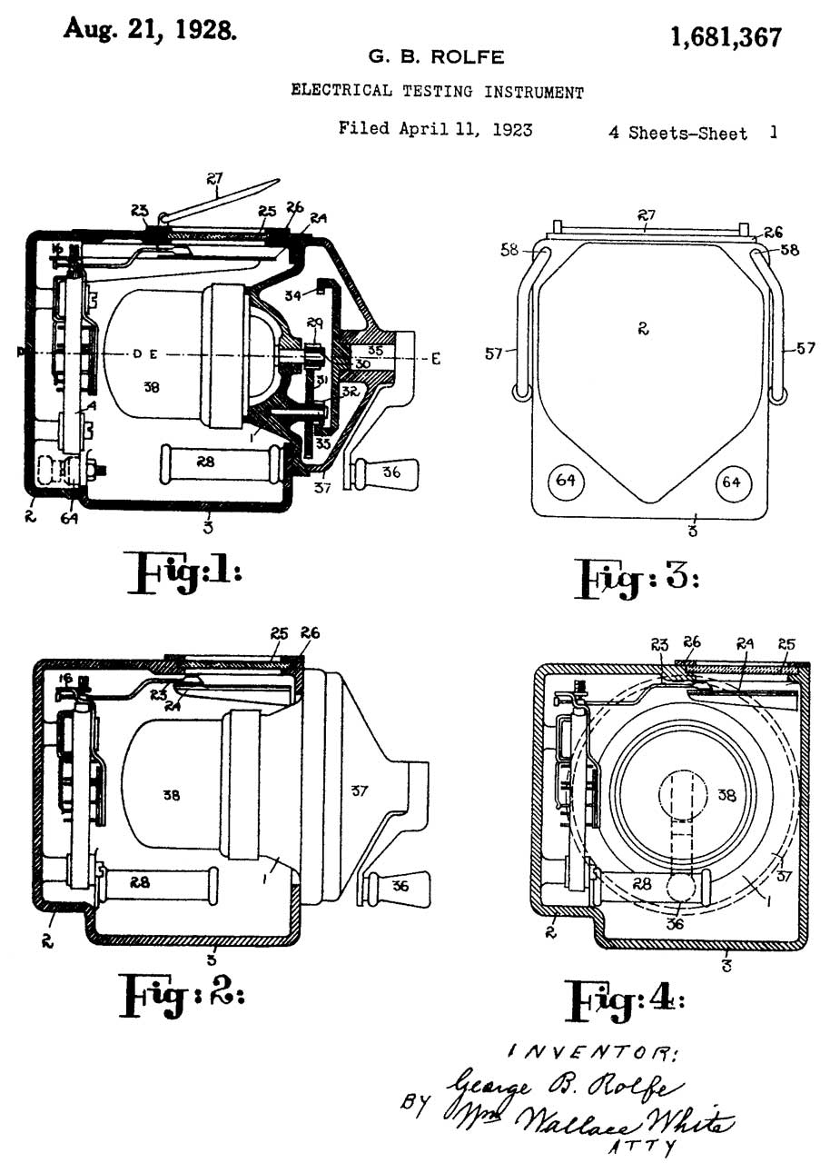
1681367Electrical testing instrument, Rolfe George Berkeley (Evershed Vignoles Ltd), Aug 21, 1928, 324/722 -
Biddle Megger - no voltage regulation instead uses a governor to regulate the magneto speed
This is what I think of as the classical Megger. It's the look of the current Made in China Meggers now (May 2020) on eBay.
1918834 Voltage indicating apparatus, Crago Paul H (Union Switch & Signal Co), Jul 18, 1933 - 324/122, 340/662, 324/72.5 - not a megger
2260234Instrument for measurement of electrical resistance, Berkeley George (Evershed Vignoles Ltd), Oct 21, 1941, 324/704, 310/156.47 -
sync mechanical rectifier
2272239 Device for measuring electrical resistance, William J Delmhorst (none), Feb 10, 1942, 324/714 - battery & vacuum tube
2326313 Alarm circuit, Trucksess David E (Bell Telephone Labs), Aug 10, 1943, 340/645, 327/545, 361/187 - failure of rectifier trips alarm
2429764 Electric fence indicator, Sidney A Moore (Prime Mfg Co), Oct 28, 1947,
340/635, 307/150, 324/122, 315/189, 324/72, 256/10, 307/132.00R
Uses Neon lamps to regulate line voltage
2460095 Electric fence indicator, Sidney A Moore (Prime Mfg Co), Oct 28, 1947,
340/635, 307/150, 324/122, 315/189, 324/72, 256/10, 307/132.00R
4408157 Resistance measuring arrangement, William H. Beaubien, Associated Research, 1983-10-04, -
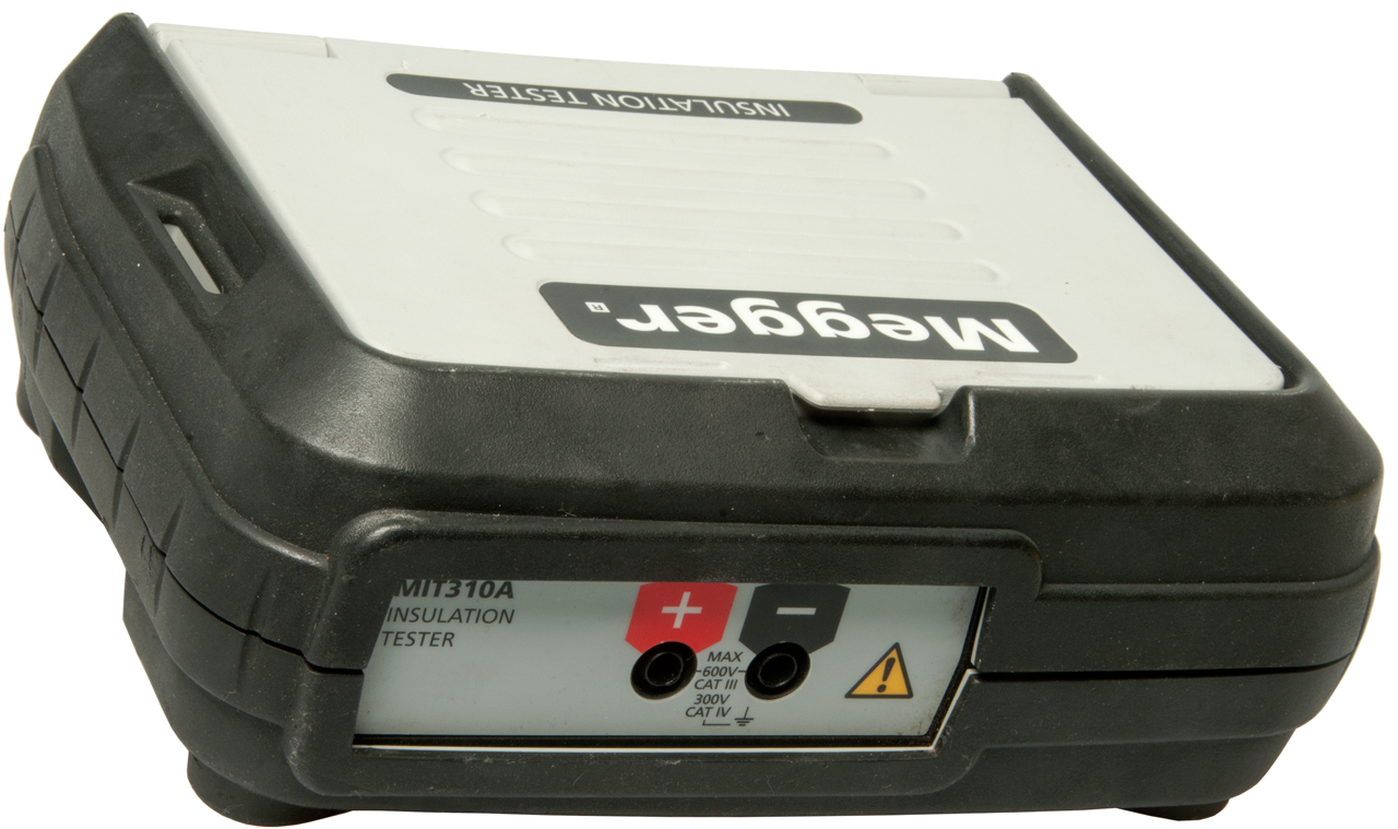
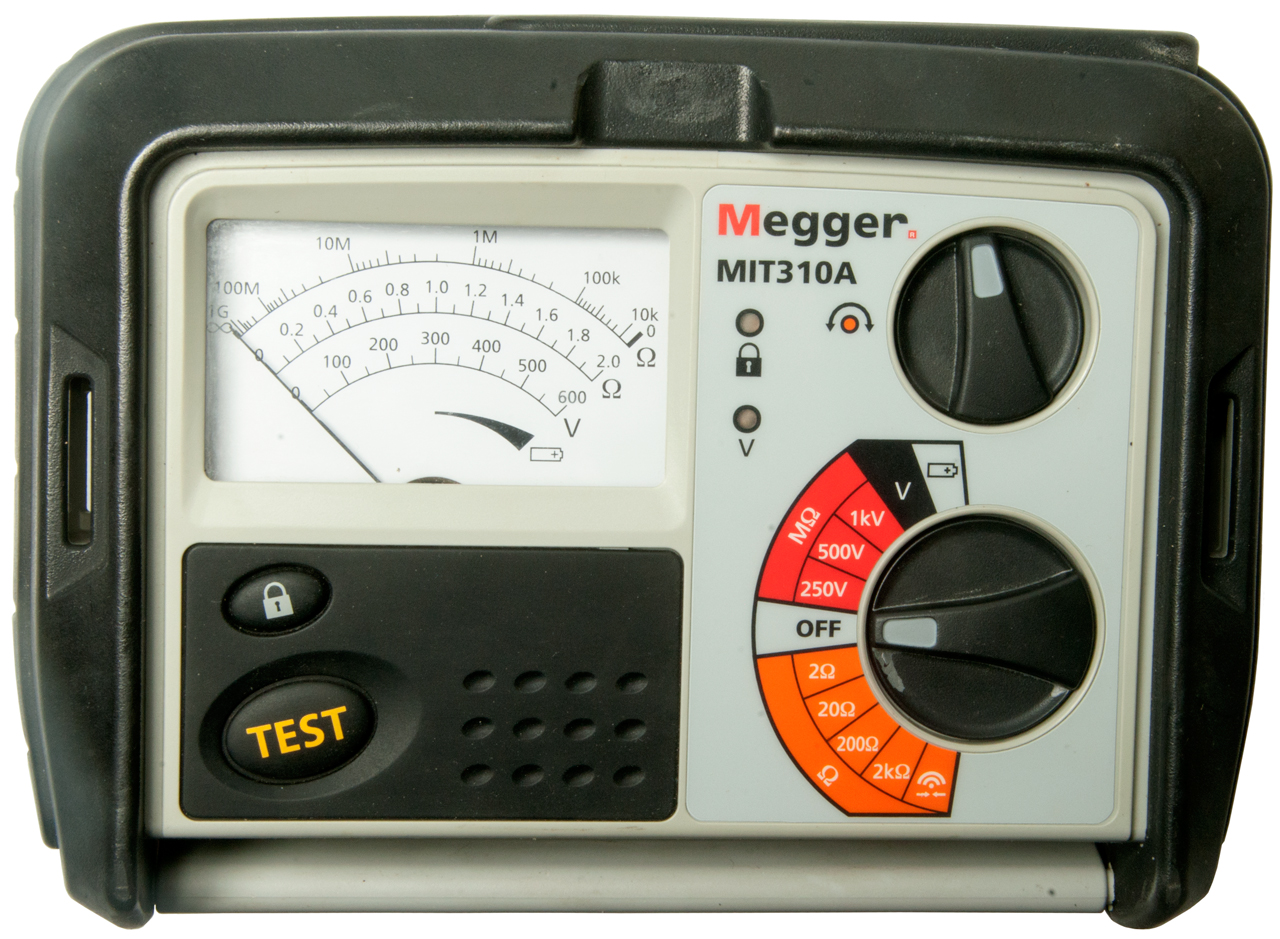
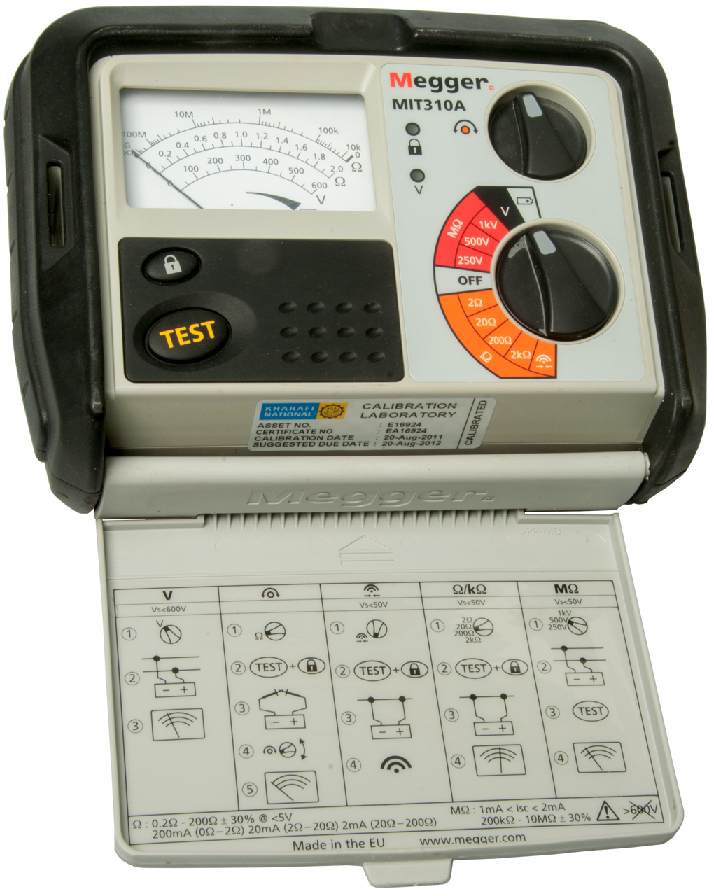
Megger MIT310A (MIT300 Series)
Versions
Model
Voltages
Voltmeter
AC/DC
Lighting
Meter
Memory
MIT300
250 & 500
No
No
Bar Graph
No MIT310
250, 500 & 1000
Yes
No
Bar Graph No MIT310A
250, 500 & 1000 Yes No
Analog
No MIT320
250, 500 & 1000 Yes Yes
Bar Graph No MIT330
250, 500 & 1000 Yes Yes
Bar Graph Yes
The MIT310A has manual selection of the resistance test current, handy for diode testing.
Note: My Fluke DMM test leads did not fit (they are not marked CAT III. The new test leads that are CAT III fit fine.
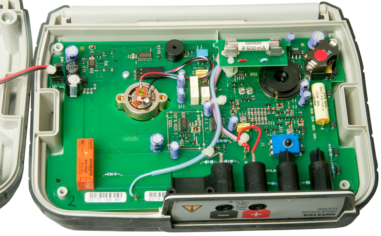
Problems
1. When taking the photos I slid the Megger across the white plastic light table and it left two black skid marks.
2. Whenever the TEST button is pressed the meter pins to the full scale stop, even in Ohms mode with the test leads shorted, on in battery test.
3. In the OFF position connecting a 1.5 V AA battery shows no deflection.
Photos
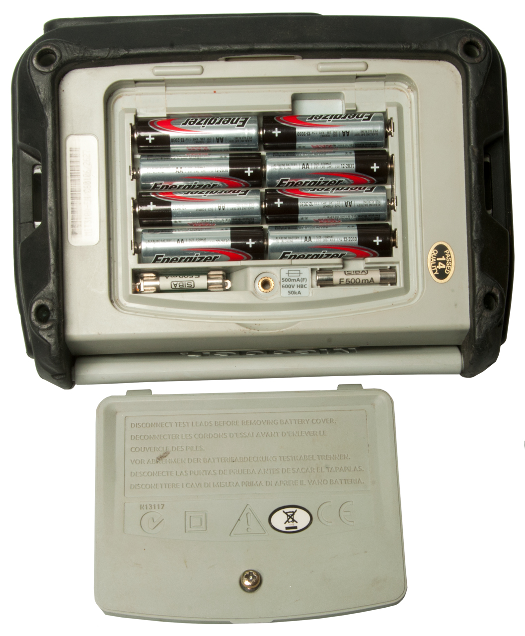
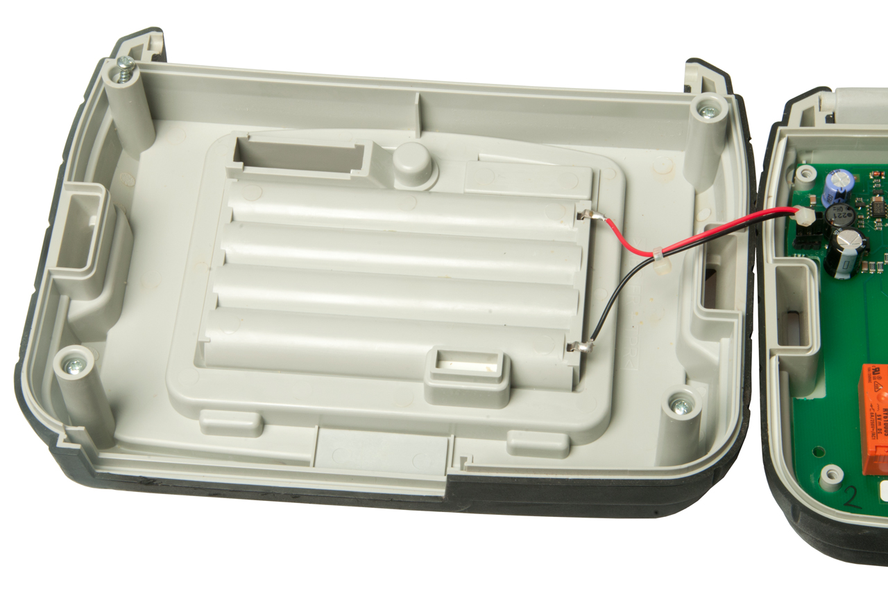
Fig 1 Eight AA cells, Fuse & spare Fuse
Fig 2 CATIII test leads MIT310A
Fig 3 Quick Operation Guide under lis.
Fig 4 Controls & Indicators
Fig 5
Fig 6
Fig 7
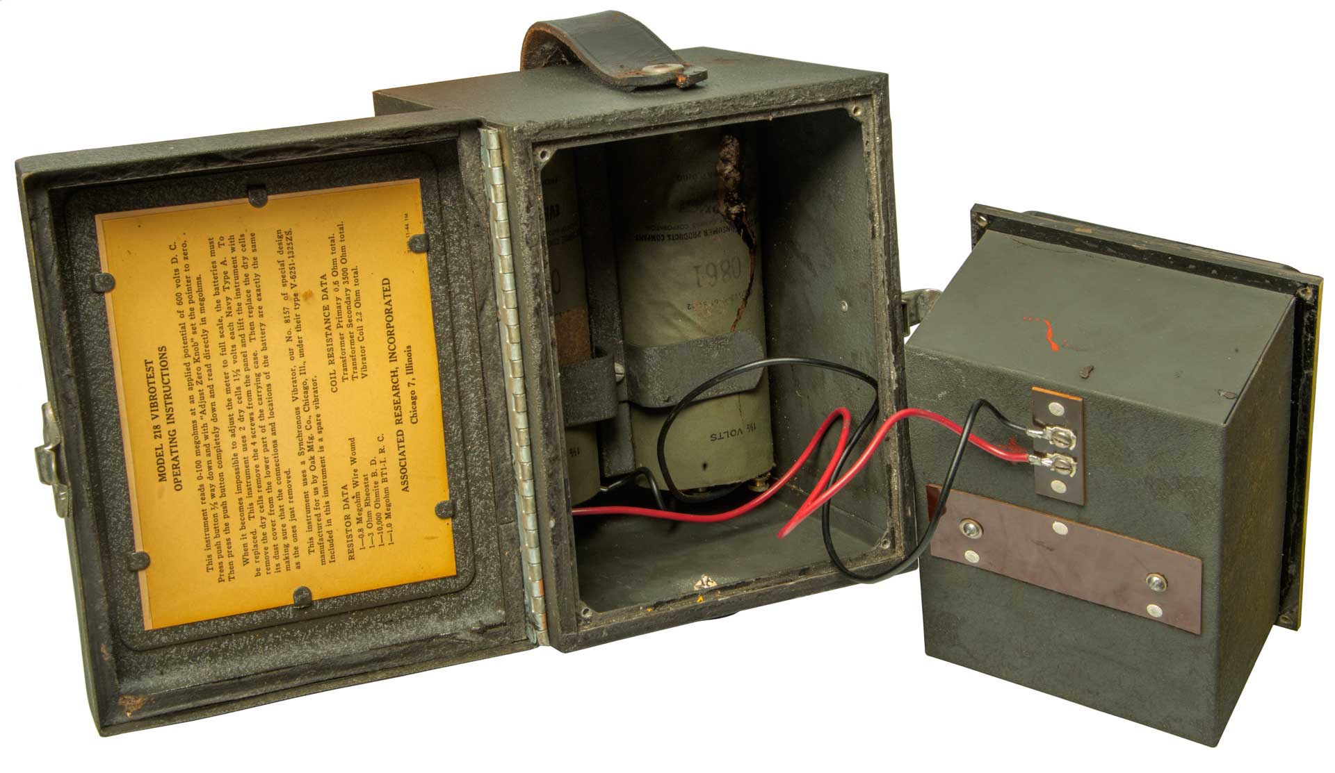
Vibrotest 218
Label:
Vibrotest
U.S. Navy Type B
Ser. No. 2181680 Date: 1-12-44
Order No.
100 Meghoms - 600 Volts
Associated Research, Inc.
Chicago, Ill.
See Associated Research patent 2375022 below that covers the Vibrotest Ground Resistance Meter.
Fig 1
Fig 2
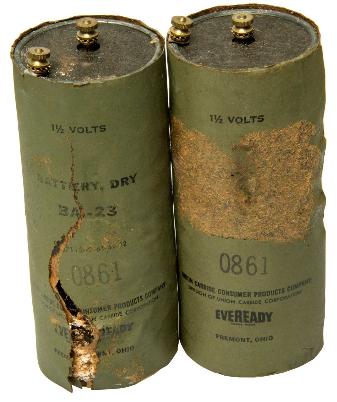
Fig 3 Uses two No. 6 Batteries.
BA-23 - No.6 Batteries
Date Code: 0861 (Aug 1961)
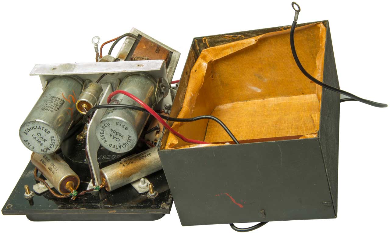
Fig 4 There are two active vibrators.
The second vibrator is not a spare.
Fig 5
The Vibrator is made by Oak Manufacturing under Oak p/n: V-6251-1325ZS.
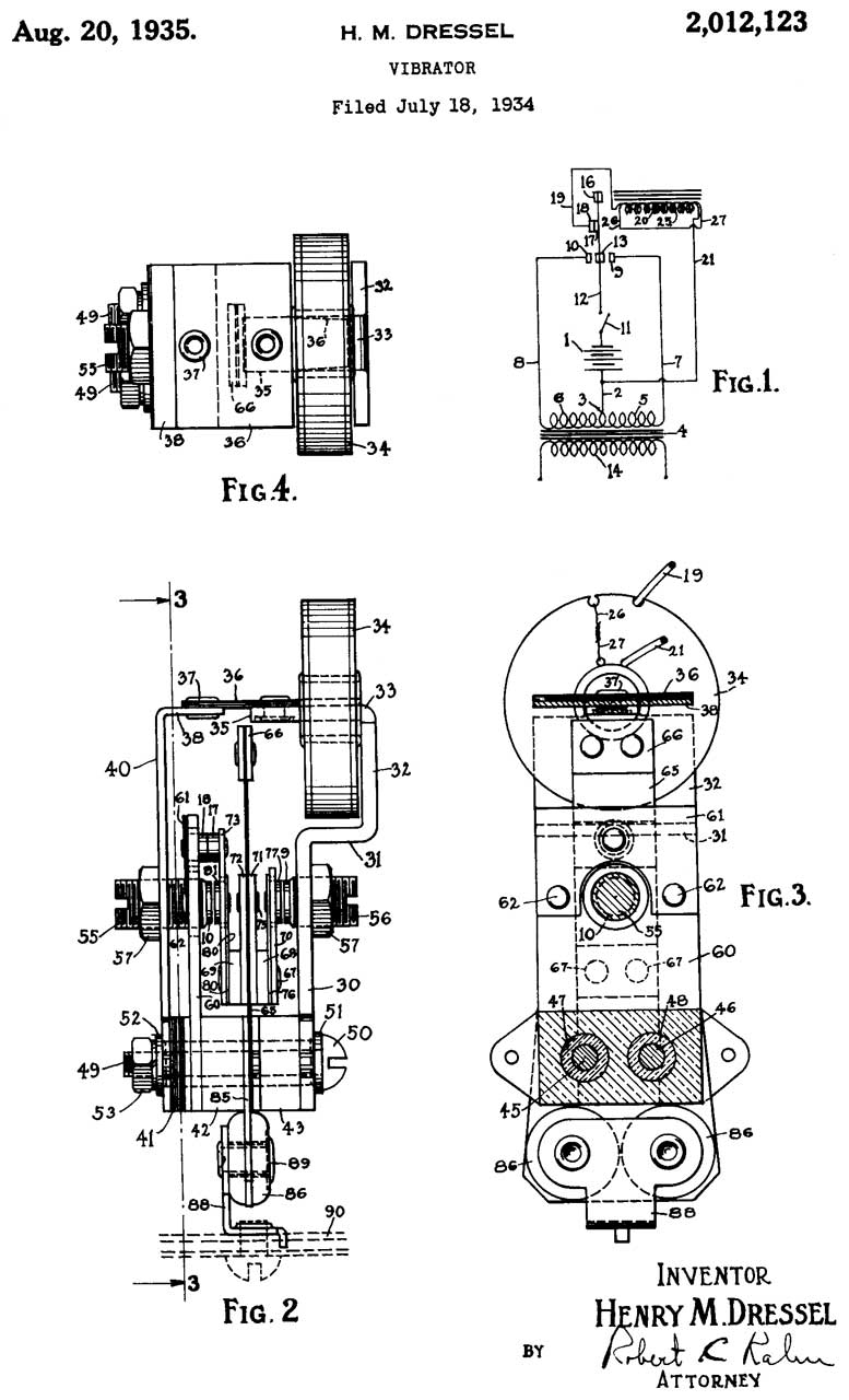
Bold patent numbers are printed on vibrators in the Vibrotest 218.
2012123 Vibrator, Henry M Dressel, Oak Manufacturing Co,1935-08-20, - shorted winding to reduce arcing
This is a first generation vibrator with an AC output.
2013513 Vibrator, Henry M Dressel, Oak Manufacturing Co,1935-09-03, - This is a first generation vibrator with an AC output.
2026772 Electrical apparatus, Henry M Dressel, Oak Manufacturing Co, 1936-01-07, -
This is a first generation vibrator with an AC output.
2053326 Vibrator, Henry M Dressel, Oak Manufacturing Co, 1936-09-08, -This is a first generation vibrator with an AC output around 50 or 60 Hz.
2065597 Vibrator, Edward J Mastney, Oak Manufacturing Co, 936-12-29, - Insulated secondary contacts, first generation
2078316 Vibrator, Henry M Dressel, Oak Manufacturing Co, 1937-04-27, - This is a first generation vibrator with an AC output.
2096962 Vibrator, Henry M Dressel, Oak Manufacturing Co, 1937-10-26, - This is a first generation vibrator with an AC output.
2140792 Vibrator, Henry M Dressel, Kenneth C Allison, Edward J Mastney, Oak Manufacturing Co, 1938-12-20, - quiet
2140807 Vibrator, Edward J Mastney, Oak Manufacturing Co, 1938-12-20, - quiet
2148193 Vibrator, Henry M Dressel, Oak Manufacturing Co, 1939-02-21, - arc reduction
2213854 Vibrator, Raymond E Wood, Oak Manufacturing Co, 1940-09-03, - This is a first generation vibrator with an AC output.
2235316 Vibrator, Henry M Dressel, Oak Manufacturing Co, 1941-03-18, - This is a first generation vibrator with an AC output.
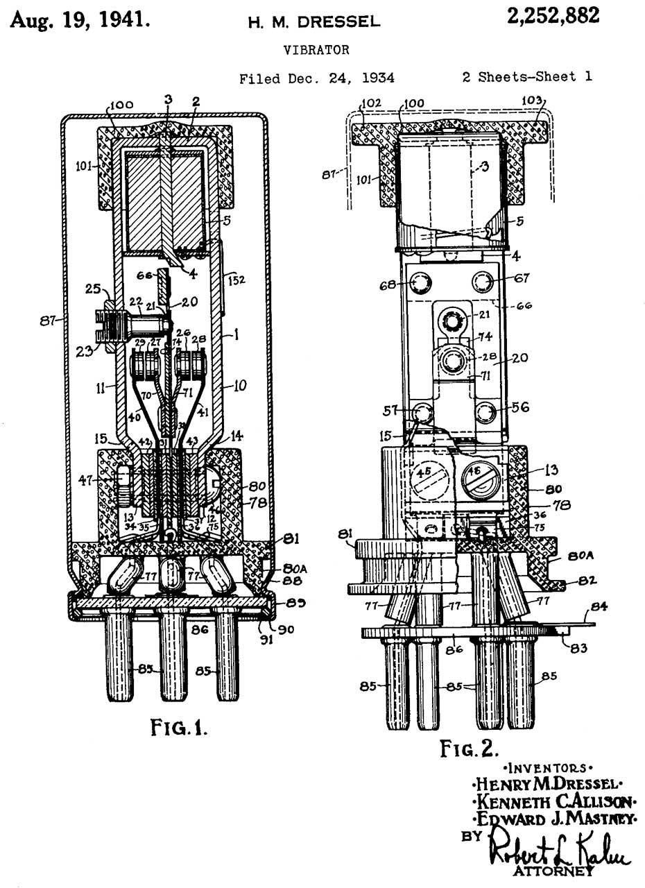
2252882 Vibrator, Henry M Dressel, Kenneth C Allison, Edward J Mastney, Oak Manufacturing Co, 1941-08-19, -
This is a second generation vibrator with an DC output. It has synchronous (self rectifying) contacts on the transformer secondary.
Maybe that's why there are 3 inventor's names on this patent, while the prior first generation patents only have 1 name?
2375022 Instrument for testing grounding resistance, George V Morris, Adler Robert, Associated Research, App: 1941-11-11, W.W.II, Pub: 1945-05-01, 324/714 - Vibrotest Model 218
Makes use of a battery power supply driving a vibrator that both switches the primary of a step-up transformer but also switches the secondary to rectify the output.
A separate contact causes the drive coil current to be turned on and off.
The outer circuit (21), shown in bold, is the High Voltage (600 VDC) test circuit.
2427898 Vibrator, Burrows Frederick Arthur, Oak Manufacturing Co, 1947-09-23, - shuttle instead of vibrating reed for higher frequency operation (200 - 300 Hz).
2513608 Vibrator with automatic regulation, Luther J Weber, Oak Manufacturing Co, 1950-07-04, - This is a first generation vibrator with an AC output. point gap controlled by solenoid to accommodate wide input voltage range.
2698366 Electromagnetic chopper, Hugh A Howell, Oak Manufacturing Co, 1954-12-28, - 400 Hz for aircraft
2859299 Chopper, Hugh A Howell, Oak Manufacturing Co, 1958-11-04, - low power 400 Hz for aircraft
2906836 Vibrators, Lawrence V Loverde, Oak Manufacturing Co, 1959-09-29, - Standard vibrator only good for 20 - 30 Watts max. This parallel one can handle 4X since is uses 4 cores.
2894094 Chopper, Hugh A Howell, Oak Manufacturing Co, 1959-07-07, - Hi impedance, low voltage circuits. Application?
2922859 Electric chopper, Hugh A Howell, Oak Manufacturing Co, 1960-01-26, - compact size
2972070 Vibrator, Lawrence V Loverde, Oak Manufacturing Co, 1961-02-14, - This is a first generation vibrator with an AC output.Constant frequency for AC phonograph motors.
Digital Multi Meters
Test Equipment
MicroWave Test Equipment
Military Test Equipment
ZM-4 Bridge
Brooke's: PRC68, alphanumeric web page index, contact, Products
for sale
Page created 2014 Feb 22