.
. 
Outside Inside
. a. If Channel Alignment Indicator ID-2921 PRC-6 is not available, the channel frequency of a Radio Set AN/PRC-6 can be changed by the substitute method described below. For this method, Battery BA-270/U and a vacuum tube voltmeter (for example, Electronic Multimeter TS-605/U) are required. Read all instructions carefully before attempting to change channels.b. The point on the probe furnished with the vacuum-tube voltmeter is too large to fit metering socket J2 on Radio Receiver-Transmitter RT- 196/PRC-6. Therefore it will be necessary to make an adapter. This can be done by soldering a piece of No. 18 solid tinned copper wire to the end of the probe or by using an ordinary paper clip straightened out and crimped axound the point of the test probe.
c. Remove the housing cover and chassis shield, install Battery BA-270[U and the new crystal in the receiver-transniitter, and set all counters to the numbers located to the right of the assigned frequency, which is found in the first column of the channel chart.
Note. The second column shows the crystal frequency corresponding to the assigned frequency. The crystals are marked with the crystal frequency on the surface opposite the pins and with the corresponding operating frequency on one side surface.d. Disconnect the whip antenna from the receiver-transmitter.e. Place the receiver-transmitter in operation by setting the power switch to the INT. position. Set the vacuum-tube voltmeter range selector switch to the lowest scale, set the polarity switch to plus, and insert the probe in pin 5 of the metering socket. A reading between plus 1 and plus 1.5 volts should be obtained. If the reading is below plus 1 volt, replace Battery BA- 270/U.
f. Set the meter range selector switch to read 90 volts, set the polarity switch to plus, and touch the probe to the jumper between pins 1 and 7 on the metering socket. If the voltage reading is below 60 volts, replace Battery BA- 270/U.
g. Set the meter range selector switch on the lowest range, set the polarity switch to minus, and insert the probe in pin 2 of the metering socket. Adjust counter 1 for maximum and note the meter reading. Turn counter 1 in a counterclockwise direction until approximately 80 percent of the maximum reading is obtained.
h. Set the meter switch on the lowest range, set the polarity switch on minus, and insert the probe in pin 3 of the metering socket. Adjust counters 3, 2, and 4, in that order, for maximum meter reading.
Note. The meter reading should increase in value as counters 3, 2, and 4 are adjusted.i. Set the meter range selector switch to the 10-volt scale and set the polarity switch to minus. The probe remains in pin 3 of the meter- ing socket. Open filament switch S1. Press the PUSH-TO-TALK switch and adjust counter 5 until maximum meter reading is obtained.j. Set the meter range selector switch to the 10-volt scale, set the polarity switch to minus, and insert the probe in pin 4 on the metering socket. A reading between minus 4 and minus 5 volts should be observed. Note this reading. Press the PUSH-TO-TALK switch and slowly turn counter 5 in the direction that returns the meter pointer to the noted reading. Continued rotation of counter 5 will cause the meter reading to swing beyond the noted reading. If the counter is turned too far, reverse the direction of rotation and return the meter pointer to the noted reading.
k. Set the meter range switch to the 30-volt scale, set the polarity switch to minus, and insert the probe in pin 6. Press the PUSH-TO-TALK switch and adjust counter 6 for maximum motor reading.
1. Set the meter range switch to the lowest scale and set the polarity selector switch to plus. Remove the jumper between pins 1 and 7 on the metering socket and replace it with a 100-ohm resistor. Connect the minus test lead to pin 1 and connect the test probe to pin 7, using the leads which were soldered to the resistor. Press the PUSH-TO-TALK switch and adjust counter 4 for minimum reading.
m. Connect the whip antenna to the receiver- transmitter. The meter set-up remains the same as for l above. Press the PUSH-TO-TALK switch and adjust counter 7 for maximum meter reading.
n. Disconnect the meter, remove the 100-ohm resistor, and replace the jumper between pins 1 and 7. Close filanaent switch S1 on the receiver- transmitter and replace the housing cover and the chassis shield.
o. As a final check after the radio set has been closed, press the PUSH-TO-TALK switch and speak into the microphone. Sidetone will be clear and undistorted if the radio set is properly aligned. Turn off the power switch after the alinement and tests have been completed.
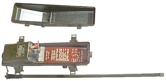
The original battery was the BA-270/U which is now long out of production. Following are a number of battery adapter options:
- Pietro - inverter uses a 6 Volt cell battery from Italy
- Home brew battery adapter plans - about $30 for a bunch of dry batteries
TNM Enterprises used to be in the battery adapter business and had one that used 4 "D" cells for A+/A-, 3 "AAA" cells for C+/C- and a center tapped string of 10 each 9 Volt batteries for B2+/B1+/B-. The outline was smaller than a BA-270 and the 7 pin socket was located so that you could put the adapter inside a BA-270 cardboard. About $30 for dry batteries
BA-491A - is a French Battery adapter holding 9 each "D" cells and using an active inverter. about $9.00 or 1/3 the battery cost of the other battery adapters. Internally 4 "D" cells are connected in parallel for the Rx/Tx filament supply and 5 "D" cells are connected in series driving an inverting power supply for the B and C voltages.
Milradio - has some as does ArmyRadio
Application Voltage Current Rx filament 1.5 V 440 mA Tx filament 1.5 V 1,000 mA Rx plate & screen 45 V 13 mA Tx screen 45 V 14 mA Tx Plate 90 V 28 mA C bias 4.5 V 8 uA
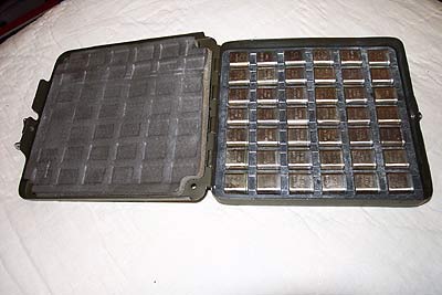
CY-853 Crystal Set
TM 11-6625-332-20P
TM 11-6625-332-34P

page created 25 Feb 2003.