One Time Flash Methods
The light sources used for photoflash (Wiki: Flash Photography) work have changed over time. The early units were chemical flash powders (Wiki). Next came flash bulbs. The popular type had a bayonet base and the professional type had a standard Edison screw base (the same as a household lamp). Next came the Flash Cube (Wiki) that worked with many high volume consumer cameras. The big advantage of these was that you got four flashbulbs in one unit and it rotated after each shot allowing for a much shorter time between exposures.Electronic or Strobe Flash
Unlike the above one time methods where you threw away the flash bulb, strobe flash has a great advantage in that the light comes from a tube that can be fired a large number of times. See the GR Strobotac web page for more about strobe lights.First Generation
Graflex Stroboflash IV (Wiki)
I had one of these and used it with a Hasselblad 500 camera setup.
A battery box holds a bunch of batteries, the final battery
voltage may be 510 Volts. From the Wiki page "It was
designed and initially manufactured in 1942 by Strobo Research,
a company founded by Edward Farber and Harold Edgerton.."
Edgerton invented the strobe flash tube and the Strobotac.| Model | Batteries |
Watt Seconds |
| I |
2 x 240V = 480V |
50 |
| II | 2 x 225V = 450V EverReady 489 |
100 |
| III | 2 x 225V = 450V EverReady 489 |
200 |
| IV |
2 x 225V = 450V EverReady 489 |
50, 100, 150 or 200 |
Sprague
250 450 DC (I think that's 250 uF and 450 VDC max)
Neg
D19054 6913
There are 8 caps and they are wired into pairs so step size is 500 uF per step.
The actual caps measure more like 300 uF each or 600 uF pere step. i.e. 600, 1200, 1800 & 2400 uF
Measured Cap Values
| Power |
uF |
| 1/4 |
618 |
| 1/2 |
1262 |
| 3/4 |
1870 |
| Full |
2434 |
There are three active terminals on the connector between the flash head and the battery box. Looking into the connector on the cord from the battery box with red dot up they are:
Upper right (red wire in battery box): Negative Variable Capacitor terminal
Upper left (white wire in battery box): Positive battery terminal)
Lower left (black wire in battery box): Positive Variable Capacitor terminal.
Note in order to charge the caps the head must be plugged in.
Looking into the flash head connector with red dot up there is a short between the top two terminals (Neg cap to Positive battery).
This seems to be wrong on two counts, the polarity is reversed and the wire color is wrong. See Fig 7 below.
Based on trying to charge the caps the polarity above is wrong, i.e. red wire is positive.
Have power supply sitting at 250 Volts at max capacitance. The current was 45 mA and a minute or two later it's down to 18 mA.
Will wait a while, the increase the voltage to 300V. After the current dropped to 3 mA (1 Watt power) raised the voltage to 300 and for a few seconds the current limited at 500 mA but then quickly fell to 18 mA. I've tried to fire the flash at each voltage (200, 250, 300, 350, ) but so far it has not fired. Wiki: After Storage
Note: When I opened the battery box for the first time I notices that tell-tale smell of a resistor that has been overheated. But there are no resistors. When first connected to the power supply with the polarity indicated by the capacitor markings [D (+) and triangle (-)] visible smoke came out. I now think this battery box was wired incorrectly at the factory.
Trigger
The trigger socket is the same as a USA AC mains 2-prong line cord. That would allow use of the then common AC mains extension cords for flash trigger.I'm still waiting for the capacitors to form but it appears that the voltage is about 20% of the capacitor voltage.
So, if the caps were charged to their max voltage of 450 V the trigger would be at 90 Volts.
When the trigger is shorted the voltage goes to zero, but when the short is removed the voltage climbs back because the trigger capacitor charging.
Minus is close to the support and Positive is close to the back where the label is located.
Note a 489 (NEDA 728) battery adapter might be made using 25 each 9 Volt batteries, maybe using 5 each of the 45VS adapters.
Fig 1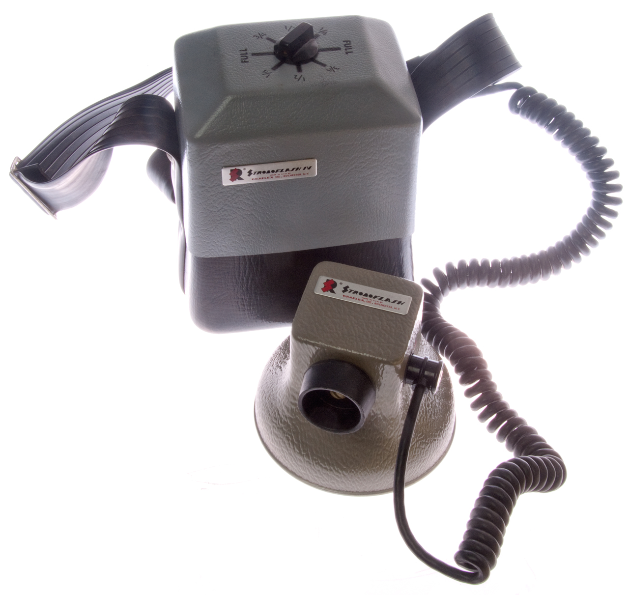 |
Fig 2 2-Prong trigger socket
accepts the then common 115VAC extension cords.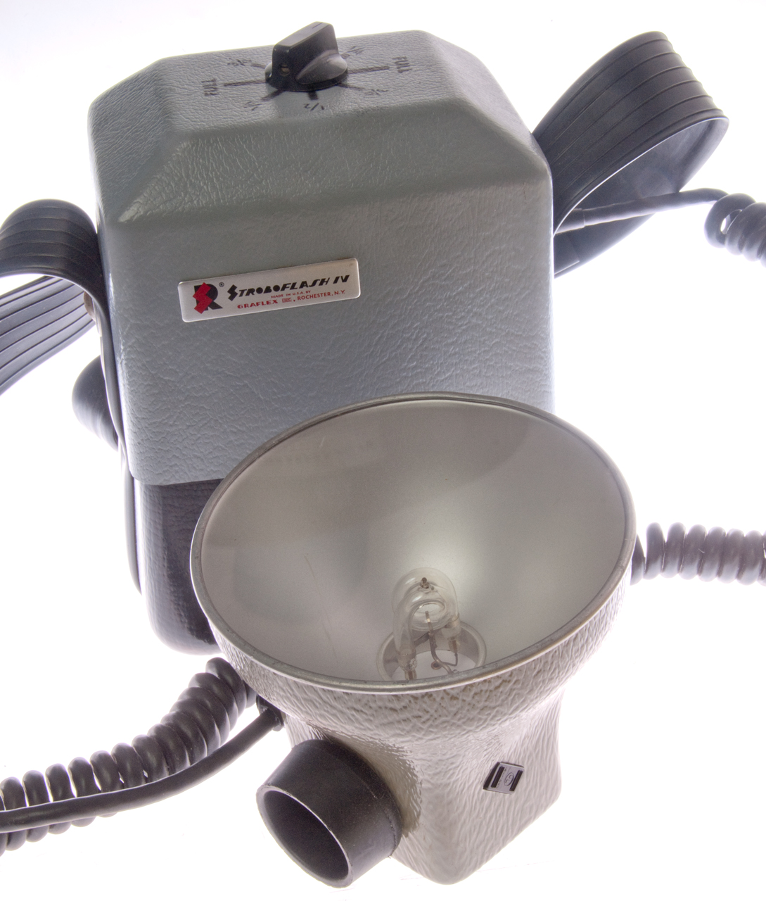 |
Fig 3 Space available for two batteries
is about 4.5" x 6"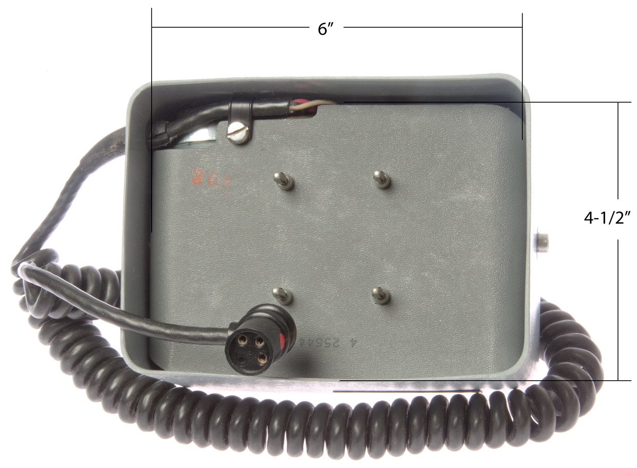 |
Fig 4 Pencil line between banana
plugs is internal short connection. Although the
HV connector has 4 holes only three of them have
terminals. Ground, HV and trigger. By
placing the HV capacitors in the battery box and running
a long coiled wire to the flash tube the inductance in
the flash circuit is much higher than when there is a
physically short path for the connection between the
caps and the flash tube.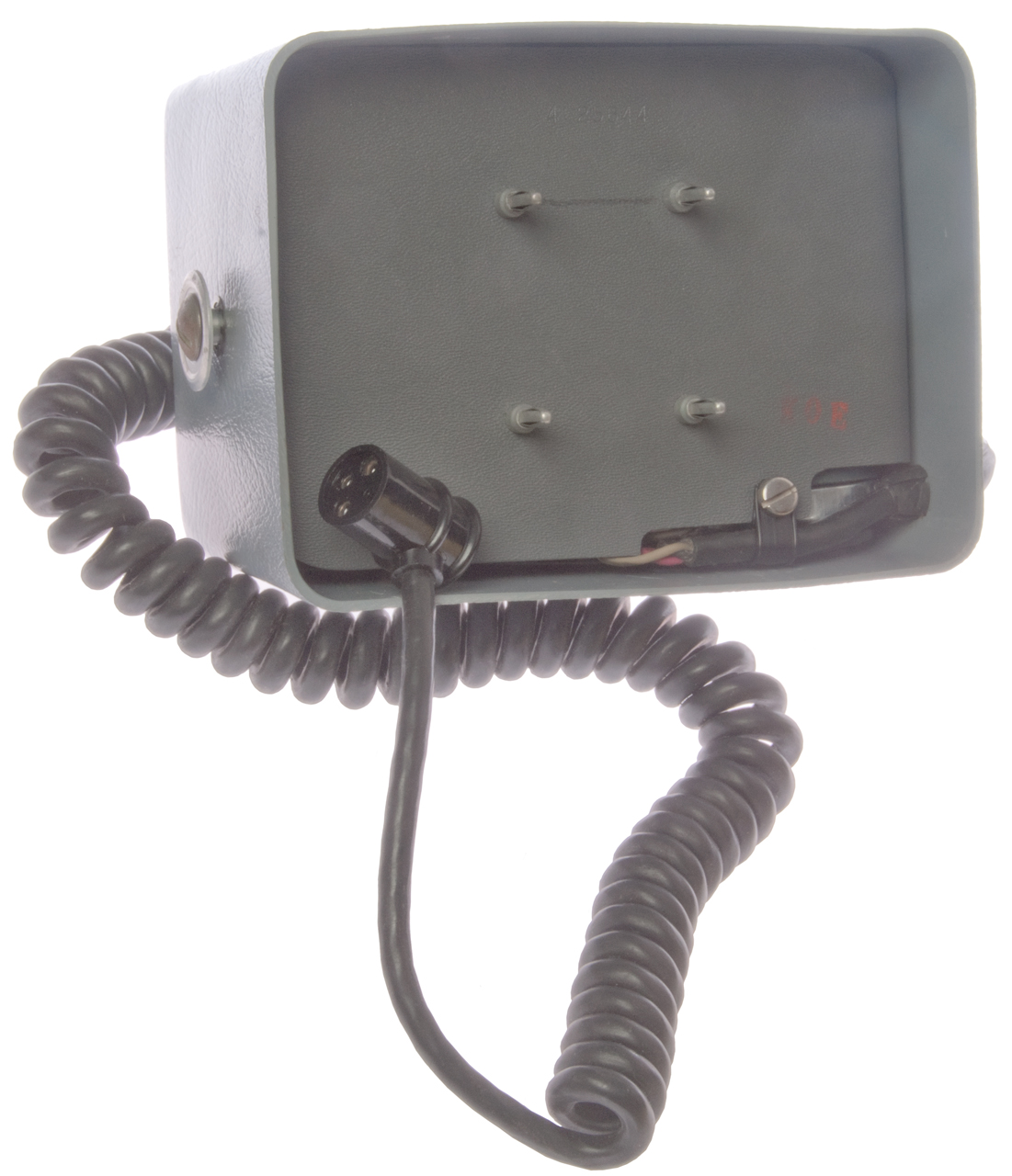 |
Fig 5 Idea for Battery Adpater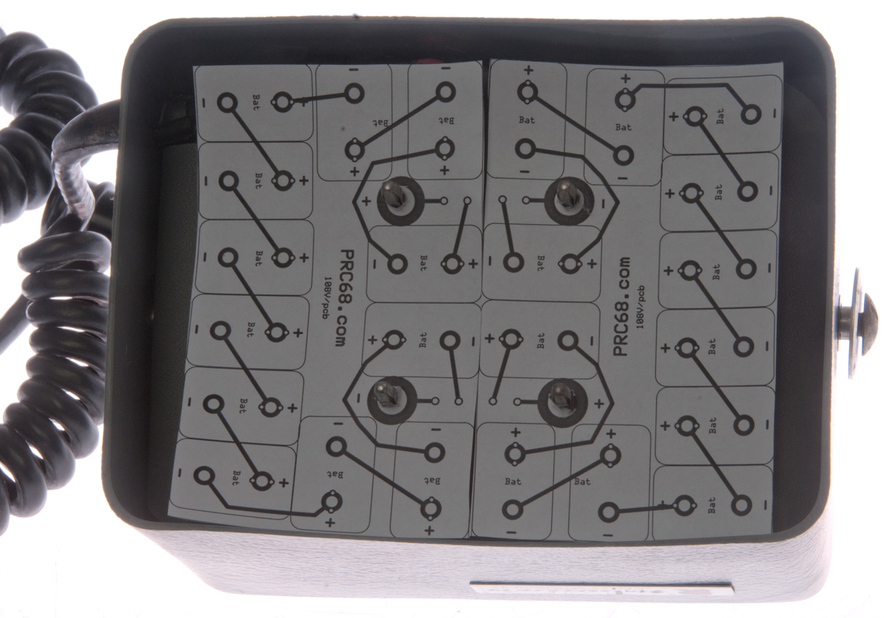 |
Fig 6 Inside battery box is just a switch
and 8 caps.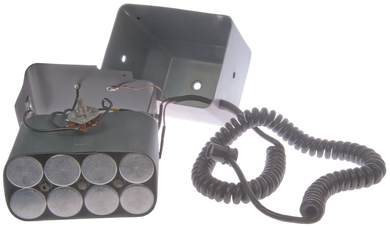 |
| Fig 7 Note my analysis had the
polarity wrong and it's been reversed in this photo. The current is dropping over time unlike with the wrong polarity is was around 88 mA and staying high. This is a Consort EV625 Electrophoresis (Wiki) Power Supply Rated at: 600 V, 500 mA, 150 Watts. Got it on eBay for about $50 including shipping. A much lower cost than buying a regular HV bench power supply. Was sold AS IS, but it seems fine to me. A little tricky to program, i.e. the first method must be a ramp then the second method can hold the voltage for up to 99h59min. 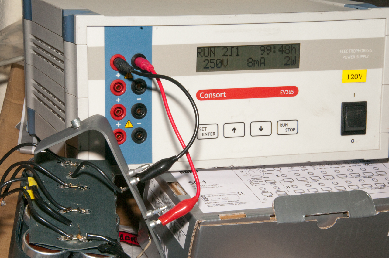 |
Graflex Strob 250
This is a newer lower power version of the Graflex
Stroboflash IV. It uses a single510 Volt Eveready
No. 497 battery.
The box holds only a battery and there is a 2 conductor cable
that runs to the flash head. The connector on the side
of the battery box has a male and a female contact.
There may be capacitors in the handle of the flash head since
the handle part is not detachable from the head.
Fig 1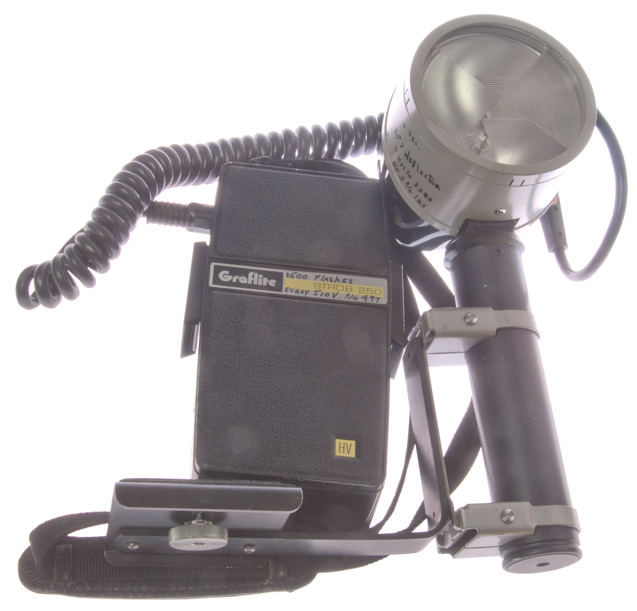 |
Fig 2 Wein WP-XL Battery-less Ultra
photoflash Slave This has a photocell that senses a flash and triggers the strobe. It also has a PC flash socket at the bottom center that may or may not work as an interface between the HV trigger and a modern camera? Let me know. 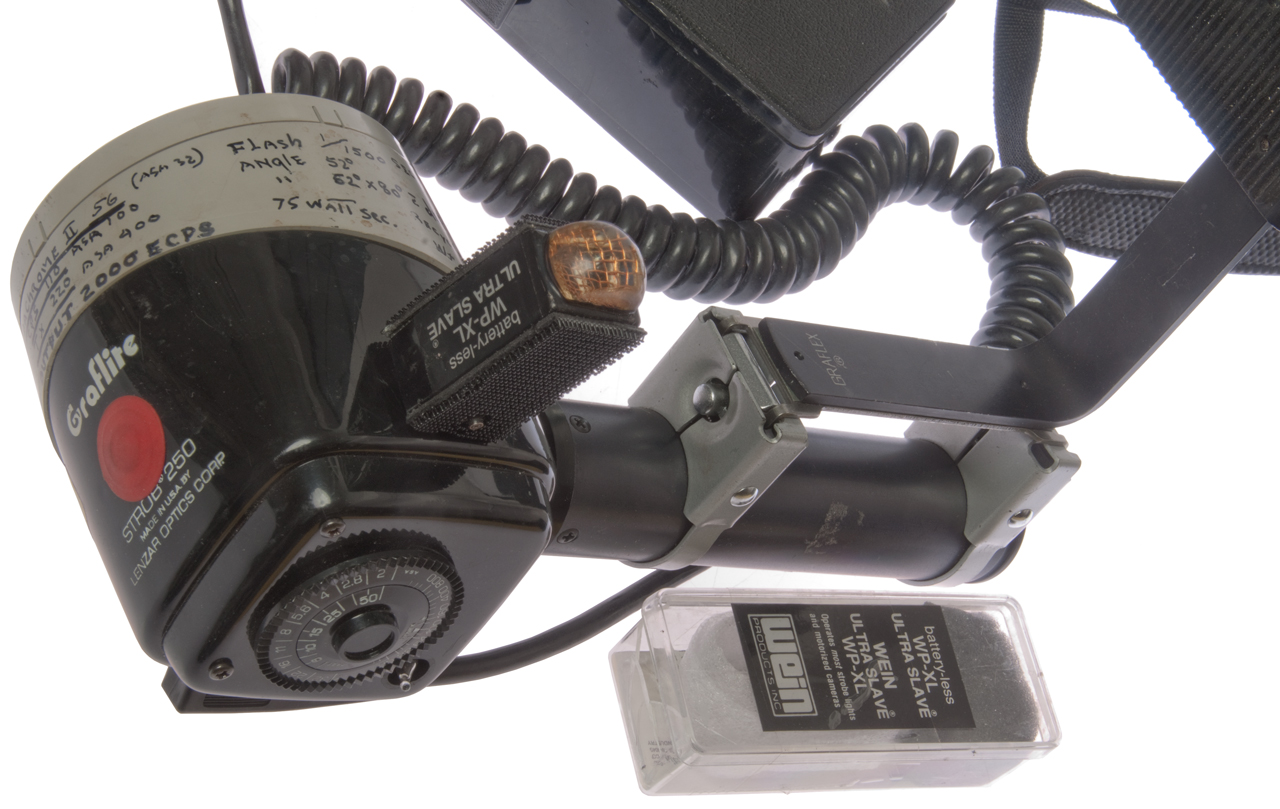 |
Graflex Booster/Analyzer
Reference Graflex Historic Quarterly Vol 14, Issue 3, pg 7
(also has the Graflex SlaveSync).
For use with the Graflex Strobomatic 500 HV and Graflex Strob
250 and by adding the adapter cord Stroboflash power packs can
be tested.
This is a small box with three functions.
Boost
A charging function intended to "top up" a carbon zinc type
battery. But this is a controversial concept on a
primary battery.
A GE diode marked GE 6RS5GH30BAB1 (with a high forward
resistance) rectifies the AC coming out of the power
transformer and the half-wave signal is fed to to the
battery. The diode is a spring loaded stack of
disks, probably Selenium (Wiki).
GEJ-1238A
Instructions Selenium Rectifier Stacks - shows the 6RS
series, and mentions the low current cells, but no specs.+ 233
VDC on the shrouded (female) contact in boost mode (do not see
how that's going to charge a 500 V battery?, maybe the
rectifier is no good?).
Battery
Measures battery voltage and can be used to get an idea of how
the caps are working.
Load
A way to check the health of a battery by measuring battery
voltage with a 3k4 load (500V / 3k4 Ohms) about 150 mA load.
Fig 1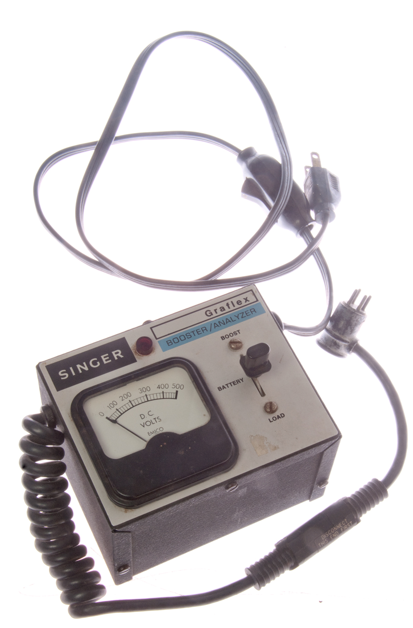 |
Fig 2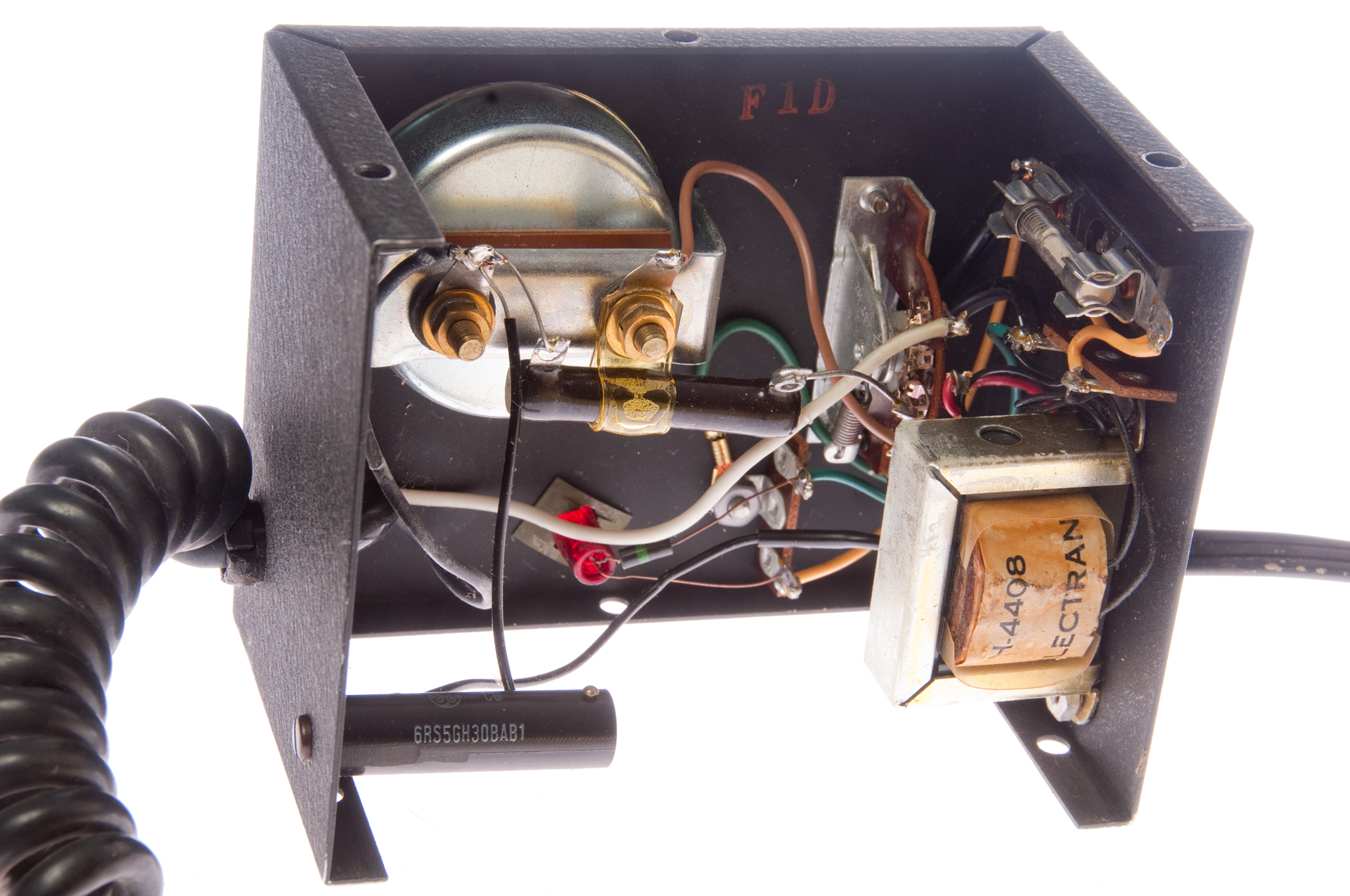 |
2668945
Electgrical Measuring INstrument with Permanent Magnet
Restoring Means, William
E. Pfefler, Electromechanical
Instrument Co., Feb 9, 1954 - tag on back of meter