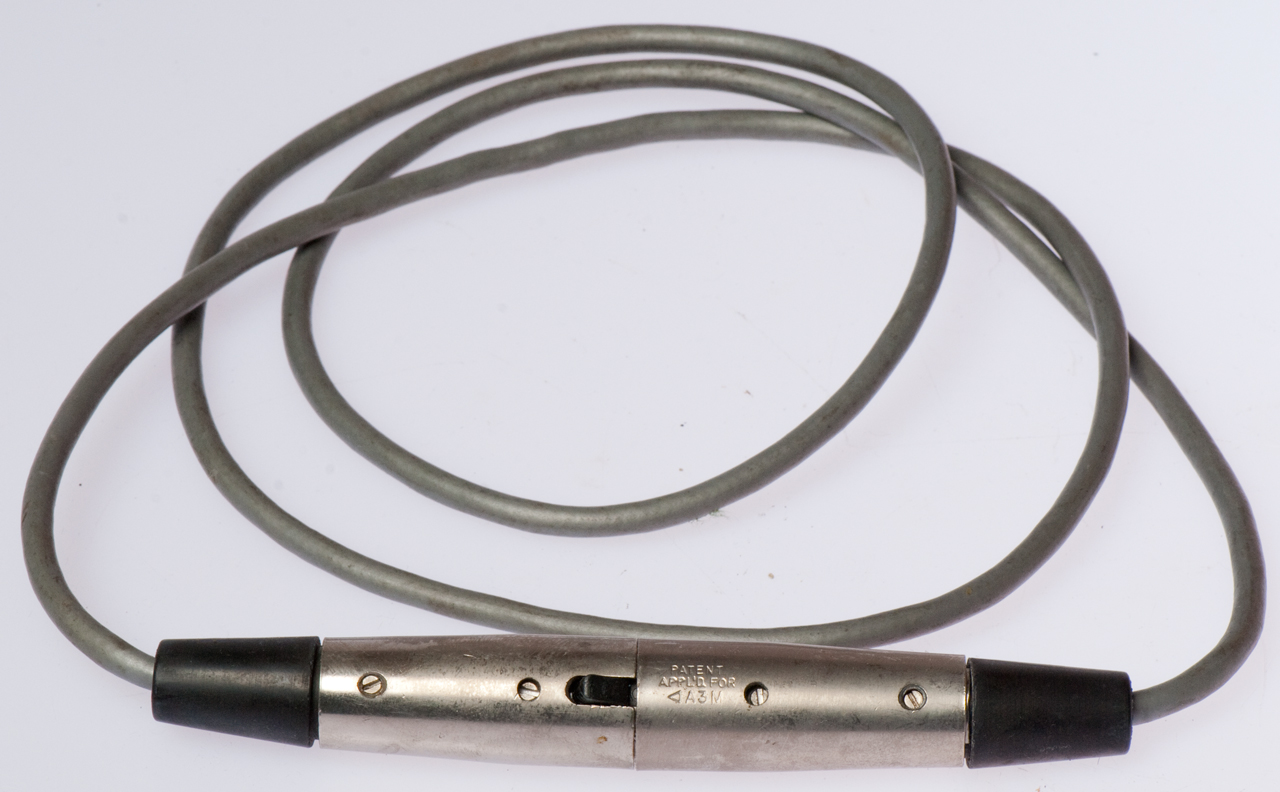
1307 Transistor Oscillator &
|
1307 Transistor Oscillator |
1307 Transistor Oscillator
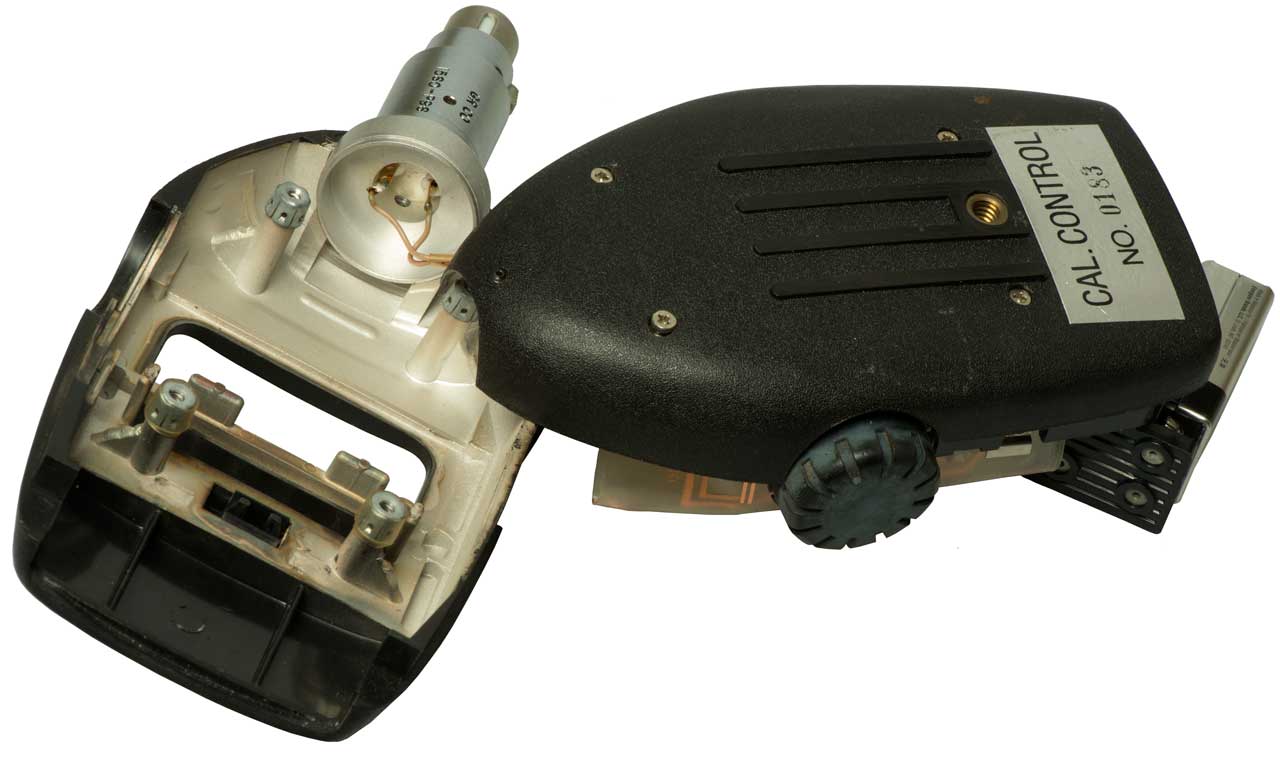
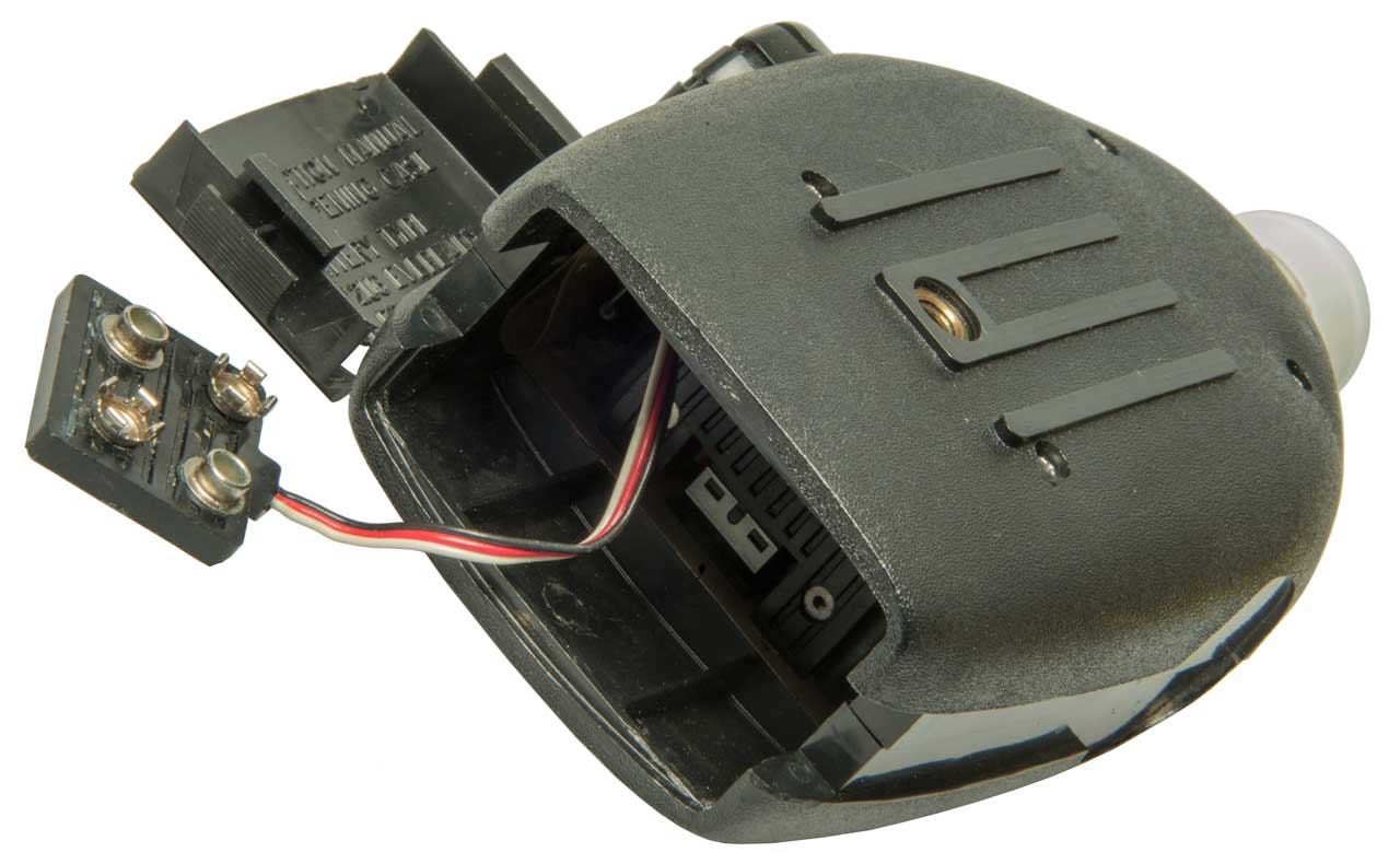
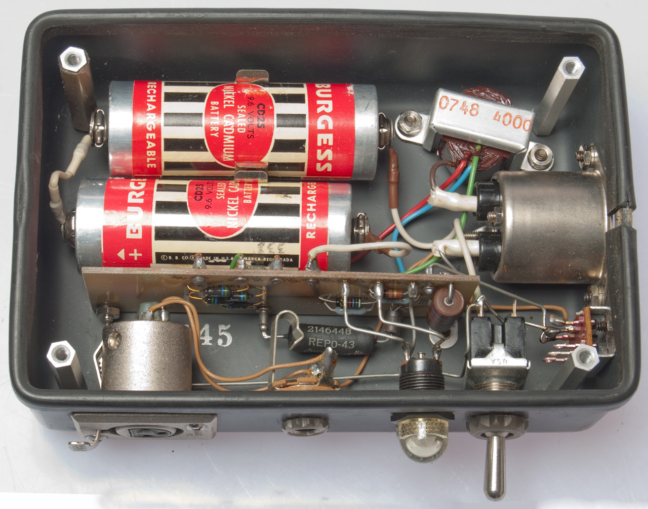
Battery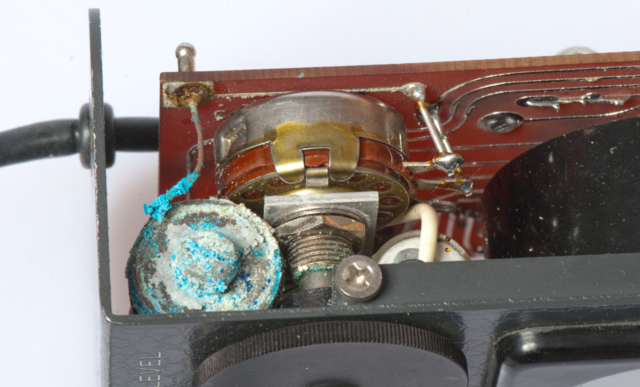 The battery is held by a matal strap clamp that's difficult to access. Why would they solder in a battery and make it so difficult to change. Ans. It's a Mercuty battery and was expected to be replaced by the factory. The corrosion from the battery locked the Level pot and the two set screws holding the Level knob on the pot shaft. Kroil freed up the pot shaft and one of the pot set secrews. Will need to wait till tomorrow to see of the other set secrw gets free. There are patent numbers on the bottom of the battery: ETAL 2542575 Alkaline Dry Cell, 2712586 ? 2636062 Electrochemical Cell and Self-Venting Enclosure, Mallory 2462998 Primary Cell with Permanganate Depolarizer RE23427 Primary Cell with Permanganate Depolarizer, |
Battery Removed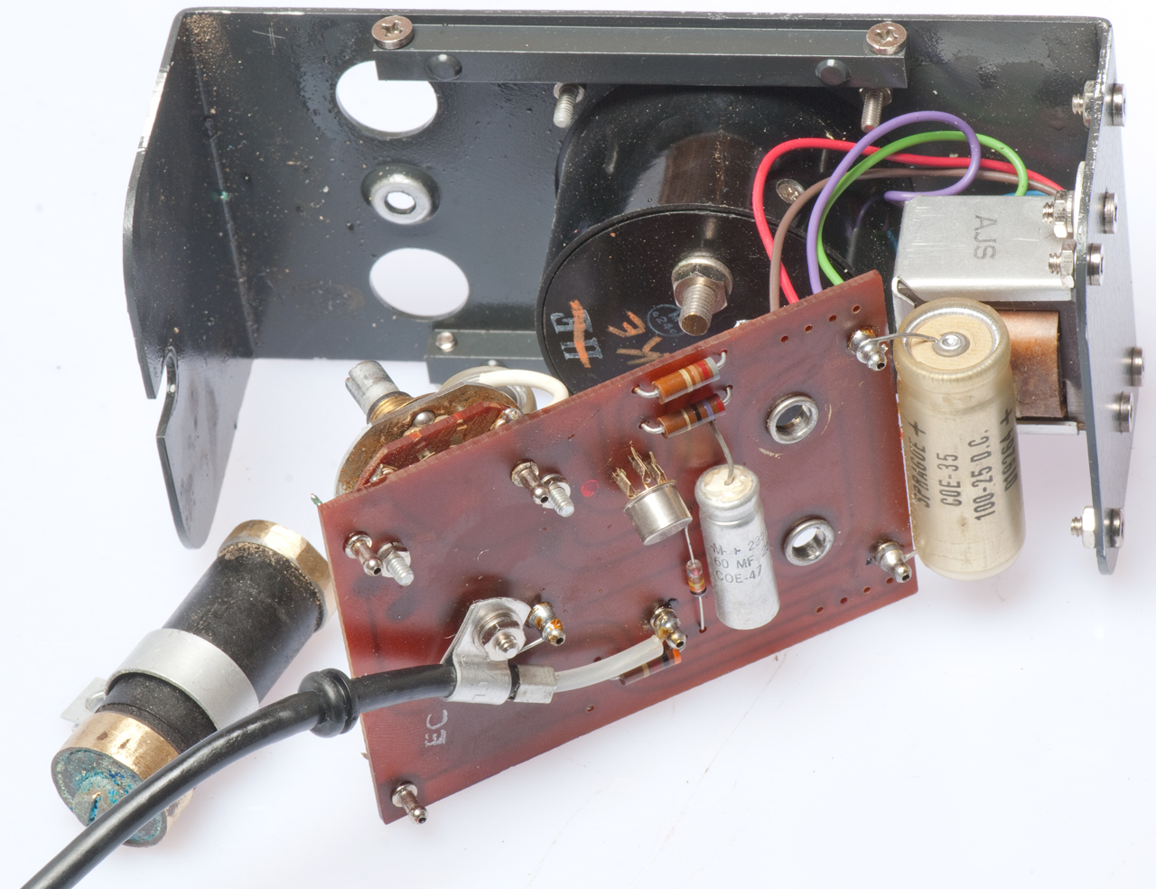 |
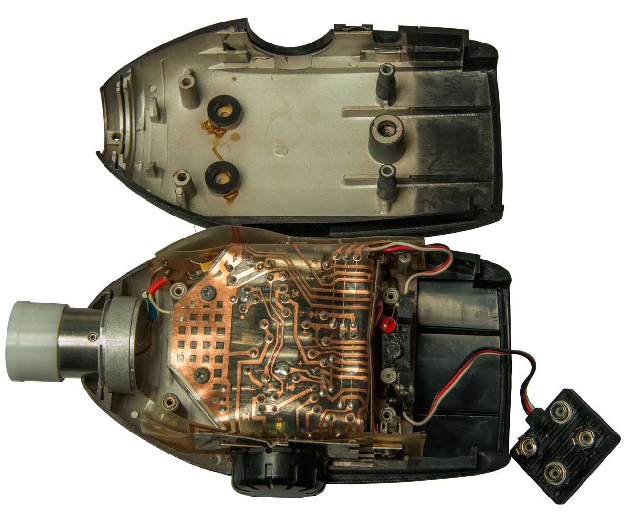
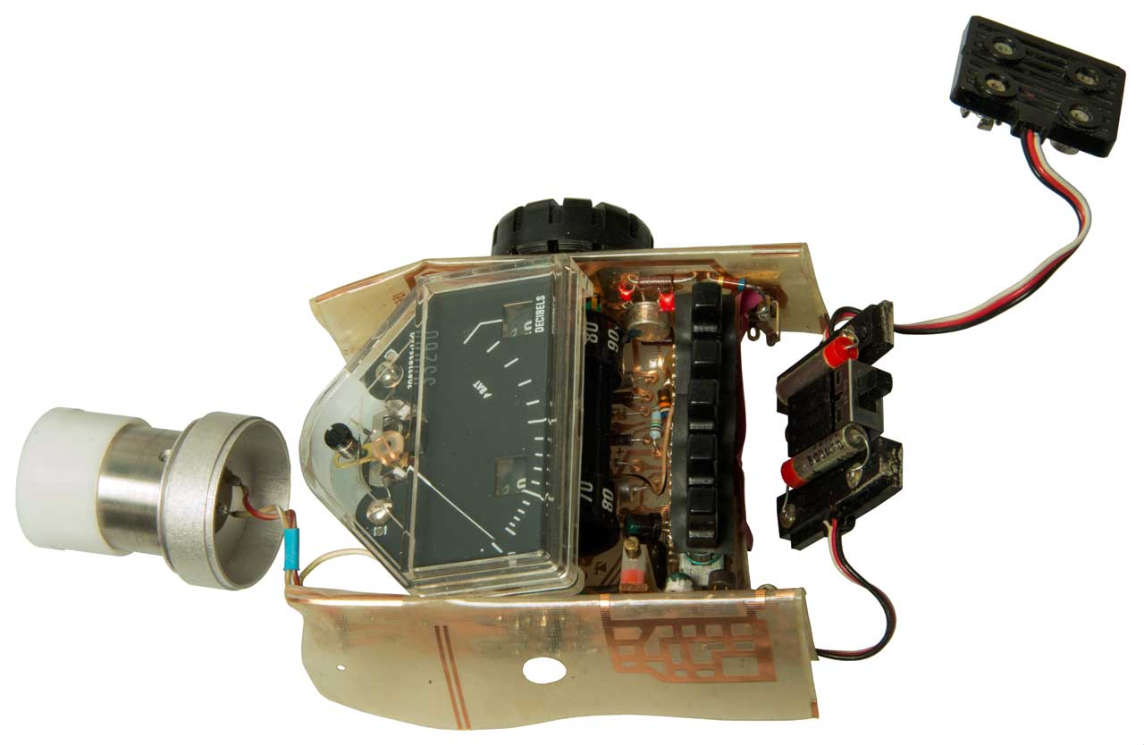
To remove the battery: Remove the two knobs (requires being able to turn them to access the two set screws on each shaft). Remove the screw that between the two knobs. Remove the two nuts on the back of the meter movement. Fold the board out and remove the hex spacer that holds the battery clamp. In the photo at left the top electrical contact is (+), you can see "+" scratched on the back of the front panel. Notice the battery is like a bar bell with ends that are larger in diameter than the center so it can NOT be slipped out. |
|
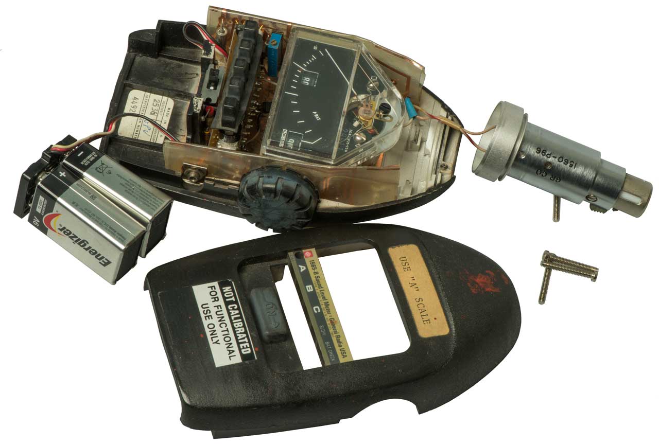
| With
the Level pot at max it takes at least 3.4 V (6 ma) of
battery to get the meter to read 2V (the calibration value
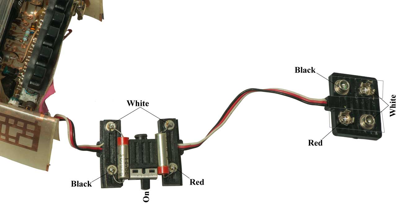
for the 1552-B. With the battery voltage at 9.0 (5 ma) the level pot has plenty of room on both sides of a meter reading of 2V. A 9 Volt battery is a little too big to fit where the old mercury battery was. An A23 battery (12 Volts) is very small. I soldered a red and black wires and confirmed that the polarity was correct. Then folded the wires so the point to the opposite end and applied heat shrink tubing. Soldered into the 1307 without using the bracket since it's way too big and the battery is so light the leads hold it. All's well. First application is to see what's going on with the mike on the Harris RF3200ET. |
||
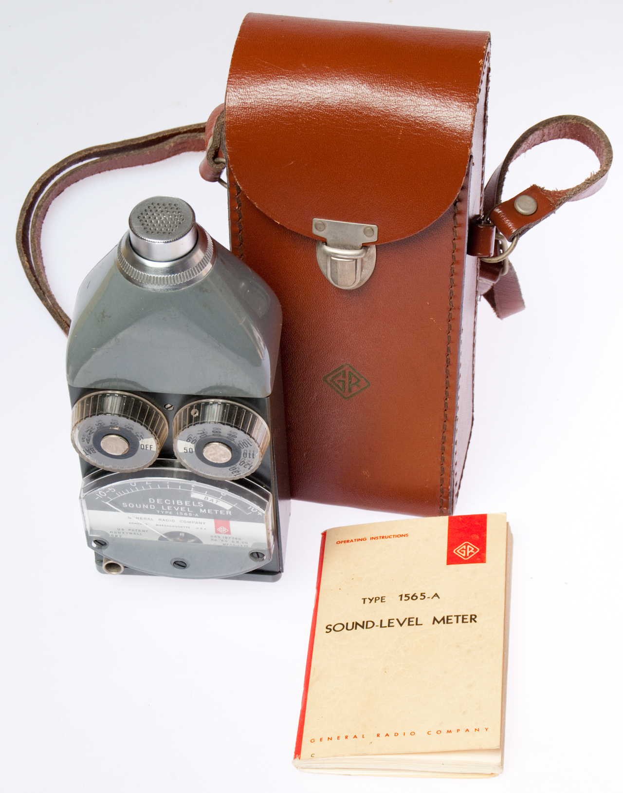
1552 Sound Level Calibrator |
1552 Sound Level Calibrator
Cavity |
|

1562-A Sound-Level Calibrator
(not part of suitcase set)Uses a Wien bridge oscillator (Wiki) (a form of RC oscillator) with an amplitude stablising thermistor. Note: the HP 201 used a lamp as the stablizing element.
Under some conditions the thermistor is not hot enough to be working correctly, hence the "Start" control setting to warm it up & test the battery. If the thermistor is cold popping and crackling sounds will be heard instead of clean tones.
| Control End Shown in 125 Hz position (red background). Circle to the right is the battery test lamp. Start/Bat Test - OFF - 2000 - 1000 - 500 - 250 -125 Hz The frequencies are each twice the next lower one. Probably not designed for communications, but lab mike calibration. 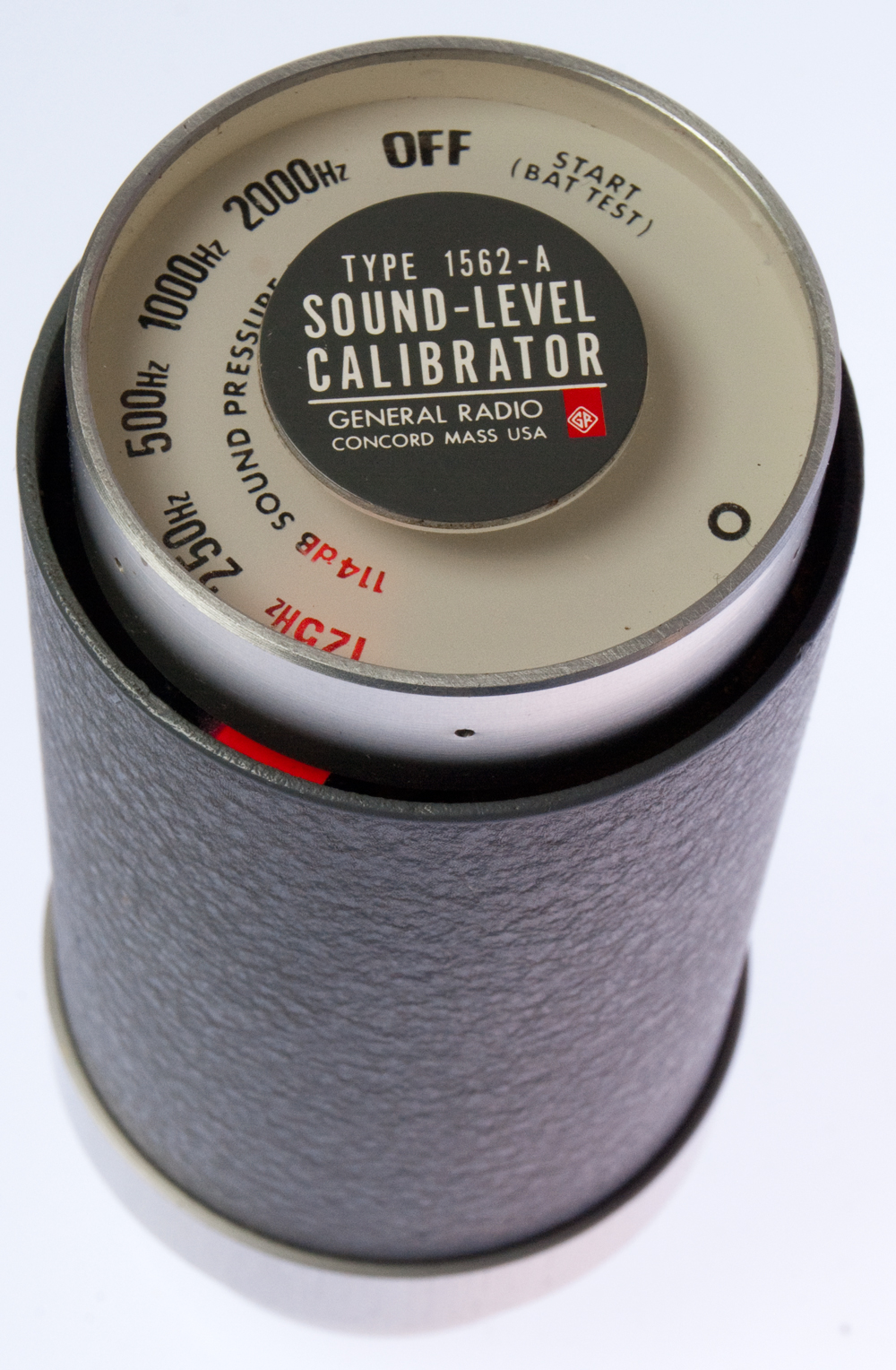 |
Source End Open end I.D. = 1.053" Adapter I.D. = 0.939" knurled screw on side allows opening case & acts as the ground side of a 1/4" phone jack.  |
Battery Compartment Takes 9 V battery with terminal on each end. NEDA 1600 Eveready 226 UK PP4 CM345 Battery test lamp (6 V @ 60 ma) at lower right. Voltage at lamp base vs. lamp current:
With 9 V at battery terminals, switch in START, lamp voltage is 6.3V caused by R110 (62 Ohm) and Q105 Vces (0.3V). 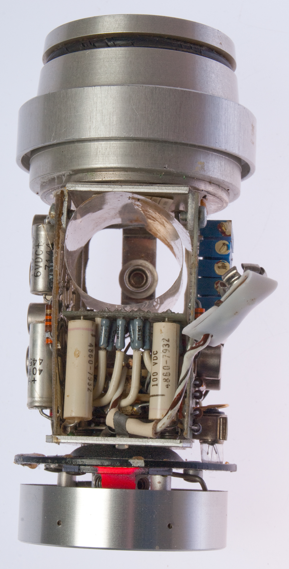 |
||||||||||||
| 4 each AAA batteries can be
used for the battery. It's only 6 V instead of 9 V and so takes longer for the thermistor to come up to temperature, but then works fine. A problem when testing the Harris RF23200ET mike is that the lowest two frequencies (125 & 250 Hz) are below the 300 to 3000 Hz voice band. |
Using button cells is not a
good idea since the current this unit draws (a few ma) is way in excess of the max design current for the button cells so they would have a very short life. |
|||||||||||||
| This gives an advantage to
the 1552 in that it can be driven from an external oscillator, like the HP 33120 Function Gen. |
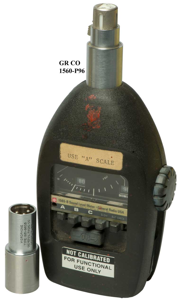
GR 1559 Microphone Calibrator
(not in this set). Manual - I have a book (haven't remembered the title yet, probably related to Sonobuoys or Helmholtz resonators, that talks about the equivalence between a mechanical model and an electrical circuit. That's to say an electrical impedance measurement can be translated into a mechanical circuit diagram. The manual is titled: Microphone Reciprocity Calibrator. The method uses a known volume inside a piezoelectric tube with a microphone at each end.Conrad Hoffman: The General Radio Corp. 1559-B Microphone Reciprocity Calibrator - (Wiki: Measurement microphone calibration)
3327071 Method of and apparatus for computation particularly suited for microphone absolute calibration, Basil A Bonk, General Radio, 1967-06-20, 381/58; 708/843; 73/1.82; 367/13 - This is the basis of the GR 1559.
GR 1567 Sound Level Calibrator
This came in a Sound
Level Measuring set.
Came with 9V battery installed and it works.
Fig 1 |
Fig 2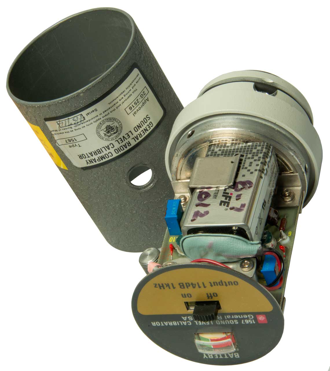 |
Fig 3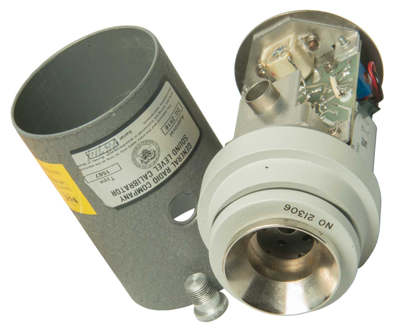 |
Mike Calibrator Patents
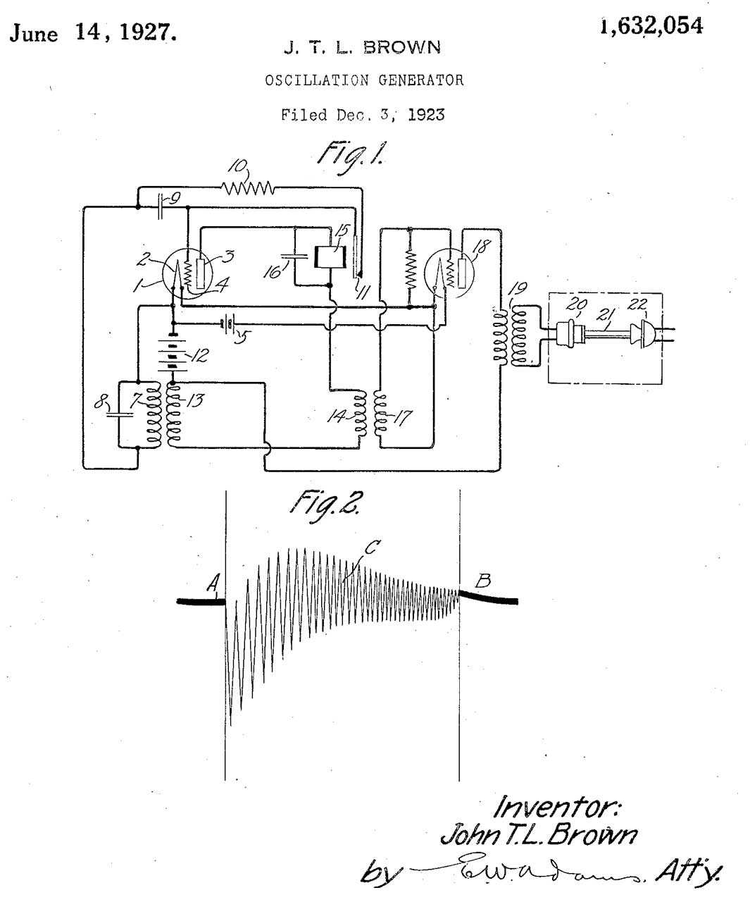 |
1632054
Oscillation generator, John
T L Brown, WE,
1927-06-14, - maybe a tube based blocking oscillator with
a very strange output waveform. Not one to be used
for a frequency response test, but rather one that has a
very unique sound. |
| 1795647
Method and apparatus for measuring acoustical impedances,
Paul
B Flanders, Bell
Labs, 1931-03-10, - very similar to 2806544 |
|
| 2224909
Acoustic device, Reginald
A Hackley, RCA,
1940-12-17, - CRT display of microphone frequency response |
|
| 2394613
Apparatus for testing microphones, Houlgate
Henry John, Marks
Philip David Rhodes, Guy
R Fountain Ltd, Priority: 1941-07-31, W.W.II,
Pub: 1946-02-12, - for close talking microphone, speaker
(1) drives small dia tube (2) making a point source of
sound. |
|
| 2530383 Microphone testing device, Nelson N Estes, Fleming Lawrence, 1950-11-21, - convoluted-wall coupler | |
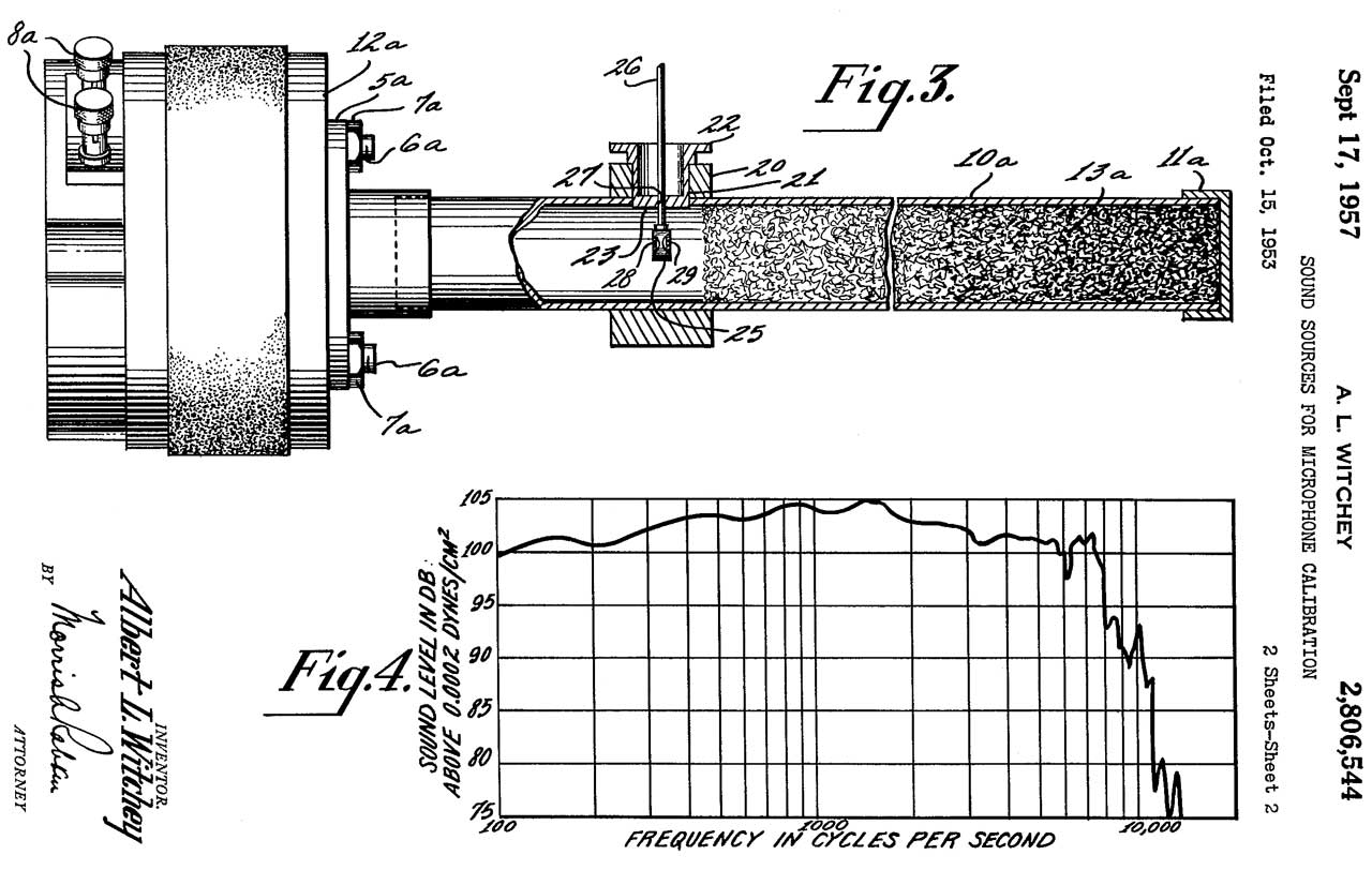 |
2806544
Sound sources for microphone calibration, Albert
L Witchey, Air
Force, 1957-09-17, - for testing noise cancelling mikes Used standard horn driver (12) and "Ozite" sound absorbing material. 1/4" hole (14) for mike is about human mouth. |
| 2837914
Acoustic impedance measuring apparatus, Stephen
A Caldwell, 1958-06-10, - has the feel of 2806544 |
|
| 2981096 Acoustical impedance meter, Ross M Carrell, RCA, 1961-04-25, - "...rapid measurement of the acoustical impedance of cloth, membranes, diaphragms, pipes, acoustical absorption material, and the like." | |
| 3093711
Testing microphones, Frank
A Comerci, Copel
Michel, Eliseo
V Oliveros, Navy
1963-06-11, - for close talking mikes -Fig 2 uses
commercial speaker driver (31) as sound source. |
|
| 3267222
Intercommunication test set, Billy
B Chipp, Mickey
H Kinkade, Navy,
1966-08-16, - "This invention relates to microphone testing devices and more particularly to a constant amplitude source of sound to be used in obtaining frequency response data of a microphone." |
|
 |
3327071 Method of and apparatus for computation particularly suited for microphone absolute calibration, Basil A Bonk, General Radio Co, 1967-06-20, - |
| 3912880
Acoustic measurement, Edwin
John Powter, Robert
Humphrey Benton, Eric
Abraham Huth, 1975-10-14, - "The frequency response of a microphone can be measured by feeding an acoustic spectrum generated from a pseudo-random bit sequence generator into the microphone and analysing the output using a Fourier analyser." |
|
| H413H
Microphone output-level tester, Arthur
S. Lelie, Navy,
1988-01-05, - looks like the RS 38-A carbon mike |
|
| 5567863
Intensity acoustic calibrator, Brian G.
Larson, Larry
J. Davis, Larson
Davis Inc, 1996-10-22, - ISO 1045: 63 Hz and 6.3 kHz |