©Brooke Clarke, N6GCE
©Brooke Clarke, N6GCE
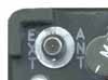
Fig 1 Fig 2 Fig 3 Fig 4 Fig 5 Fig 6 Fig 7 Fig 8
short pin is pushed up
into can, breaking wire
My prototype 1112BA Battery Adapter is working as of 14 June 2002. For status see my products for sale page at http://www.prc68.com
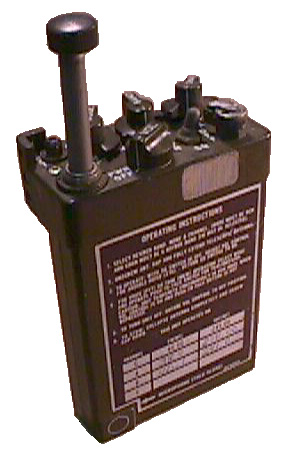
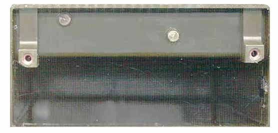
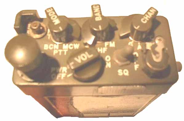
The BA-1112/U is a battery that fits on the back of the AN/URC-68 and attaches with a screw. There are two "pins" on the radio (marked "+" (close to the PTT switch) and "-". That's why there is a notch on the back of the radio (see Fig 4). NSN 6135-935-5241
The origional Mercury battery would have supplied 13.2 Volts if it was a 10 Mercury cell configuration and is considered deat at less than 10.5 Volts. The BA-1112/U has an 18 hour life in beacon mode. 5 x 4 x 1 1/4" 1.5 pounds.There are a couple of spring fingers that contact the inside battery terminals. They can get corroded (see Fig 5 left terminal), so use a pencil eraser to clean them up (see Fig 5 right terminal). Also clean up the mating surfaces on the fingers (see Fig 7). Then apply a smal amount of Radio Shack Lube Gel to both surfaces to keep out Oxygen from the atmosphere.
Current Consumption at 13.2 V In
(the prior higher current consumption figures were erroneously taken at 15.0 Volts)
Rx Tx Beacon 75 to 85 mA
max Audio Vol130 mA 150 mA 53 mA
min Audio Vol
This implies that the BA-1112/U is about 2.5 AH capacity.
The replacement battery in the out of print book "Power Up" uses 8 each "AAA" batteries which would give 1.1 AH if modern batteries were used. The Power Up book says the BA-1112/U uses 10 "AA" cells (Mercury was the chemistry) for a 13.2 VDC battery.
Single in ear type H-281/URC-68 Magnavox p/n 717084-801 NSN 5965-055-0648
This adapter allows automatic operation of the PTT switch when a laynard is pulled, like when an ejection seat leaves the plane.
MX-8197/URC-68 NSN 5020-791-1510During the Viet Nam era this was typically not used. If a radio was automatically turned on it's beacon would interfere with voice coms.
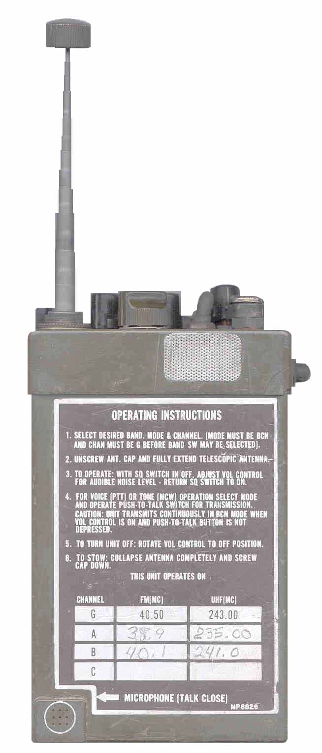
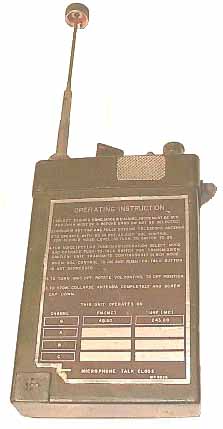
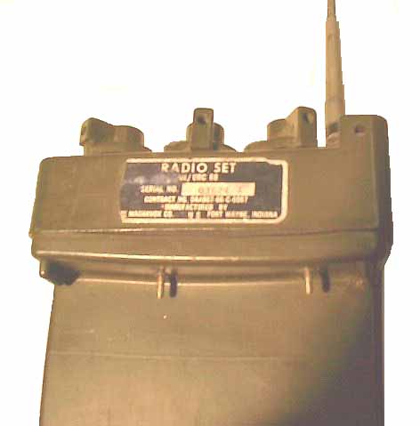
When the antenna is collapsed it activates a switch that disconnects the antenna so that the EXT ANT connection can be used.NOTE
The bottom antenna section has a ridge sticking out and this section must be pulled up in order to activate the antenna. For a long time I was not pulling the antenna all the way out.
Specified Bands
The VHF "FM" mode is specified for Tx/Rx frequencies of 38 to 42 MHz and the "UHF" AM mode for 230.5 to 250.5 MHz. This corresponds to crystal oscillation frequencies of 48.125 to 52.125 and 48.125 to 52.125 MHz respectively (i.e. the same oscillation band).220 Ham Band AM
Operation on 223.5 MHz requires the oscillator to work below spec at 46.725 and both of my URC-68 work fine.The 220 SSB calling frequency is 222.1 which might be a better choice for an AM frequency?
This would require a crystal at 46.445, slightly lower in frequency.51.0 MHz VHF FM
Operation on 51.0 MHz requires the oscillator to work above spec at 61.125 MHz and does not oscillate when tried on two radios.Stock Frequencies
There are 4 channels: G (Guard), A, B and C.
To get to the crystals remove the two phillips screws on the top (not the screws on the sides).
On this radio there are only 3 crystals installed, they are just below the Panel near the PTT switch. (see Fig 6).
Where the "C" channel crystal should be there is a small piece of foam to keep the "goop" from filling the space for the crystal.
The crystal removed from channel "B" is marked 50.225000 MHz and CR-77/U, CD8Y.The manual says that the oscillator is of the Colpitts type.CR-77/U Mil Specification
Covers oscillation frequencies of 17 to 62 MHz, 3rd overtone, series mode resonance, HC-25/U holder, +/- 0.002% tol, -40 to +90 deg C temp range
Here are some Agilent 4395A spectrum analyzer output frequencies:
The 4395A data is off a little, probably due to the span being too wide for the number of points.
Chan UHF MHz 4395A MHz FM MHz 4395A MHz Xtal MHz G 40.50 50.625 243.00 101.25, 202.5
X*2, X*450.625 A 38.9 48.75 235.0 147.5, 196.25 49.025 B 40.1 n.a. 241.0 n.a. 50.225000 C no xtal
Both the G and C channel crystals are 10.125 MHz higher than the receive frequency on the VHF FM band.The VHF FM frequency is (Xtal Freq) - 10.125 MHz.
The UHF frequency is 5* (Xtal Freq) - 10.125 MHz
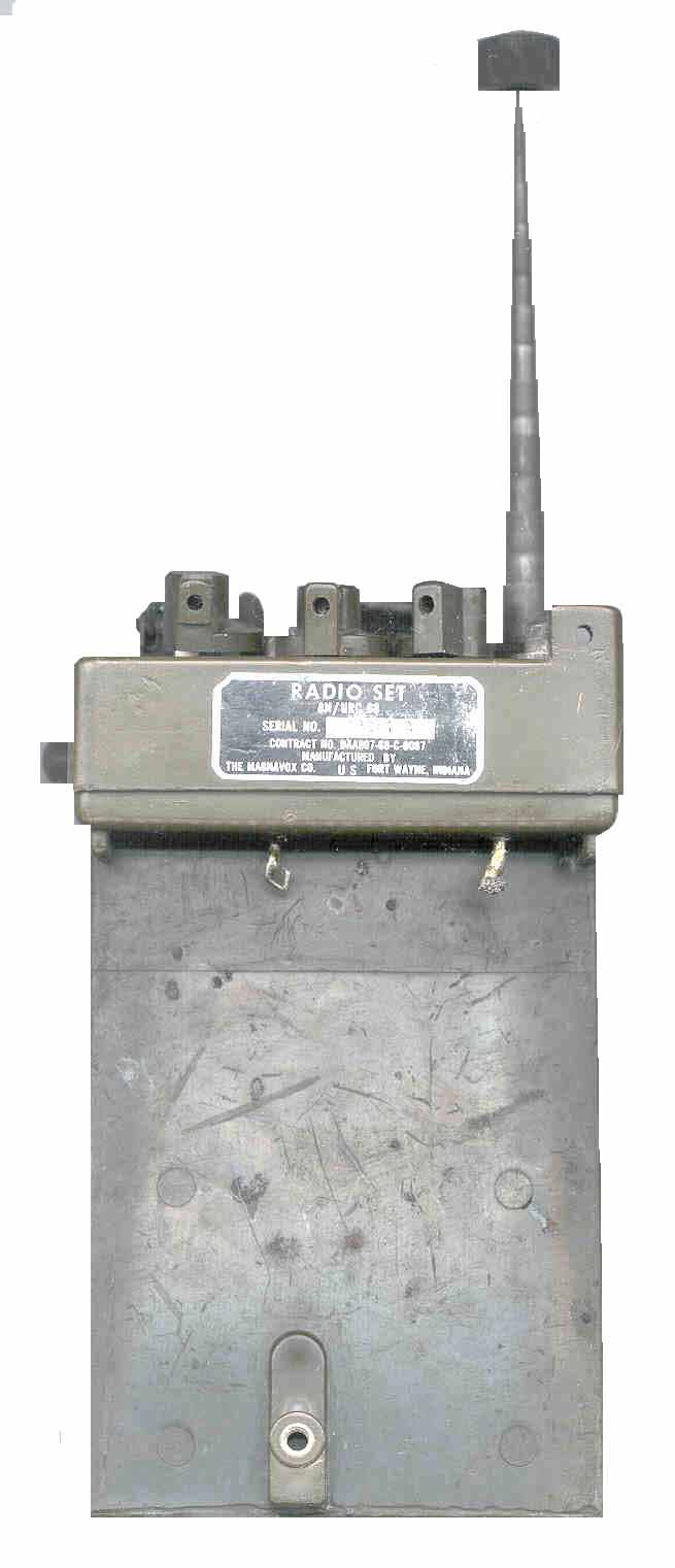
TM 11-5820-767-12 Operator and Orginizational Mainteneance Manual Radio Set AN/URC-68, August 1968TM 11-5820-767-34 Direct and General Support - includes bench test setups and schematics, although it says repair is on a module replacement basis. The construction uses integrated circuits.
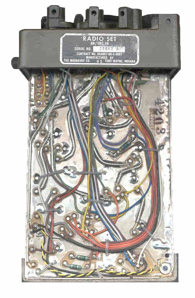
To remove the lower case just loosen the two captive screws on the panel face. Do not remove the screws on the sides of the panel, they hold the panel to the frame.
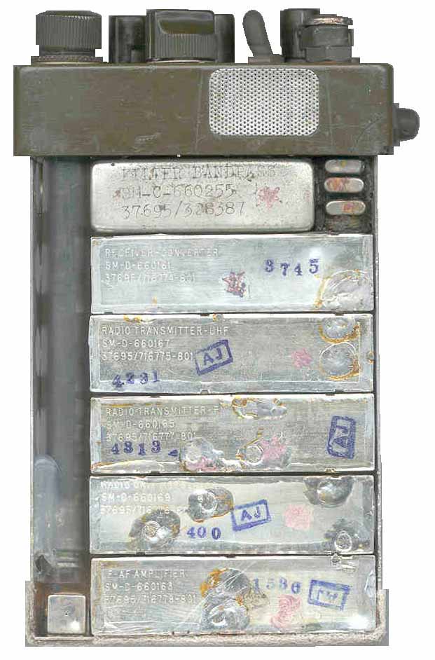
The panel and lower box are made of plastic and there is some cracking of plastic parts. The PRC-68 Family of squad radios is made with a casting for the panel and a metal box below, much stronger construction. Inside this radio uses modules that plug into sockets like on the PRC-68 series. You can see that there are no division lines between the modules because there is a printed circuit board with sockets to hold the modules. There is no flex circuit like in the PRC-68 radios, all wires in this one.The Modules are (starting form the panel (top) side):
- Name, govt part number, Magnavox CAGE #/Magnavox part number
- Filter Bandpass, SM-C-660255, 37695/328387
- Receiver-Converter, SM-D-660161, 37695/716744-801
- Radio Transmitter-UHF, SM-D-660167, 37695/716775-801
- Radio Transmitter FM, SM-D-660165, 37695/716777-801
- Radio Unit Modulator, SM-D-660169, 37695/716776-801
- IF-AF Amplifier, SM-D-660163, 37695/716778-801
When first powered up it drew no current. I checked the ON switch on the back of the VOL control and it tested OK.
The next step was to remove and reinsert all the above modules a few times. Their sockets looked about as bad as the battery contacts pictured above. After this Channels G and A are working fine, but B channel is still not there.The pin spacing is too small to fit the activity meter. While measuring dimensions on the "B" crystal, and in Fig 8 above, you can see that one pin is shorter than the other. This is because that pin has come loose and slid up into the can. This must mean that the wire between the pin and crystal is broken.
This is the field test set to check the BA-1112/U battery and to check the radio.
This is the "test facilities kit" for use in a test shop with other bench test equipment. It contains adapters to interface to various parts of the URC-68 but no stimulus generating or response measuring functionality.
Military Equipment List - Part 9 - "radio set, Rescue, Army, 38-42 and 230-250MHz, 4 chan, xtal control, WBFM, 200mW UHF, 500mW VHF, 11-16 VDC from BA-1112/U mil-type battery, common frequencies: 38.9, 40.1, 40.5, 41.0, 235.0, 241.0, and 245.5 MHz,
TM 11-5820-767-12/34/35, Magnavox"U.S. Military Portable Radios By Alan Tasker, WA1NYR - SAR-Rescue Radios-Chart 5 - BA-1112 battery on back.
Americal Division Veterans Association - Rescue of Saber 6 -
SRU-21/P survival vest - with pocket for URC-68
Description from Sea Coast Surplus on eBay:
This is a small (6"x2"x 3 1/2") handheld size, Vietnam Pilots, and Aircrew Survival Radio, it fit in pockets, Survival Vests, Ejection Seats, etc. This sends and receives FM radio signals. Transmits both voice, morse code, and automatic homing beacon. This one works great, includes 3 crystals which make 6 channels, 3 in 40 MHZ area, and 3 in 240 MHZ area. has Emergency Frequencys of 40.50, and 243.00. plus 4 others (I'll supply you with frequencys when shipped as I have to open it up), It takes a small battery which slides into recessed area on back, but I used another small 9volt battery held in place with bands, and ran small jumper wires to two terminals (+, -), as I said, works great. Has a 40" collapsable antenna, earplug socket, controls, small external antenna connector, ETC. Made by MagnavoxThe EXT ANT connector has 2 lugs and an O.D. of 0.264".
Back to Brooke's Military Information, Time
& Frequency,
Electronics,
Home
page
This is the [an error occurred while processing this directive] time this
page has been accessed since since 4 Aug 2001


