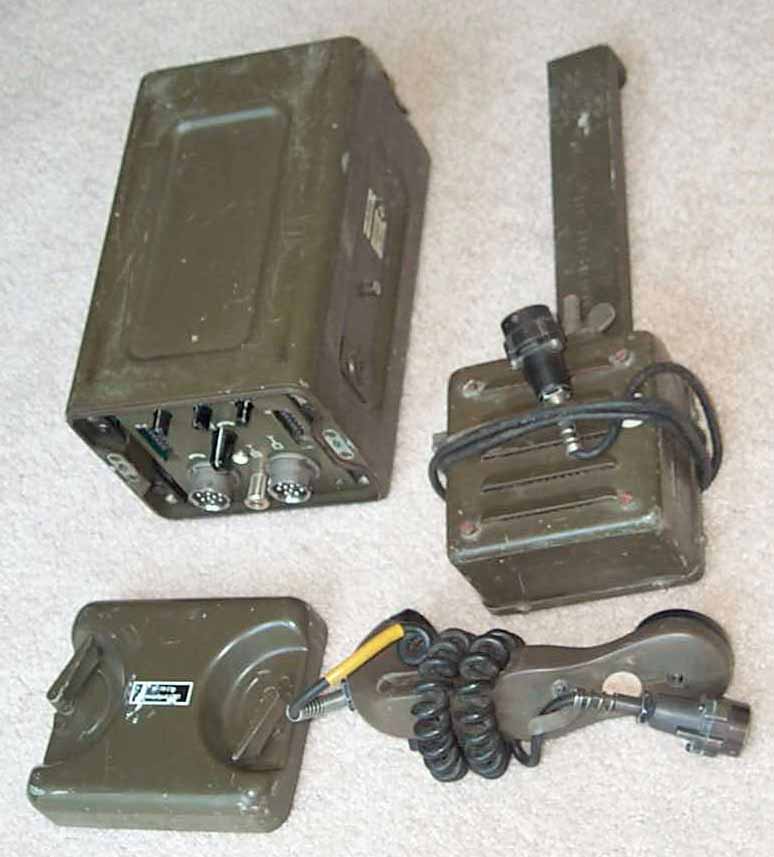
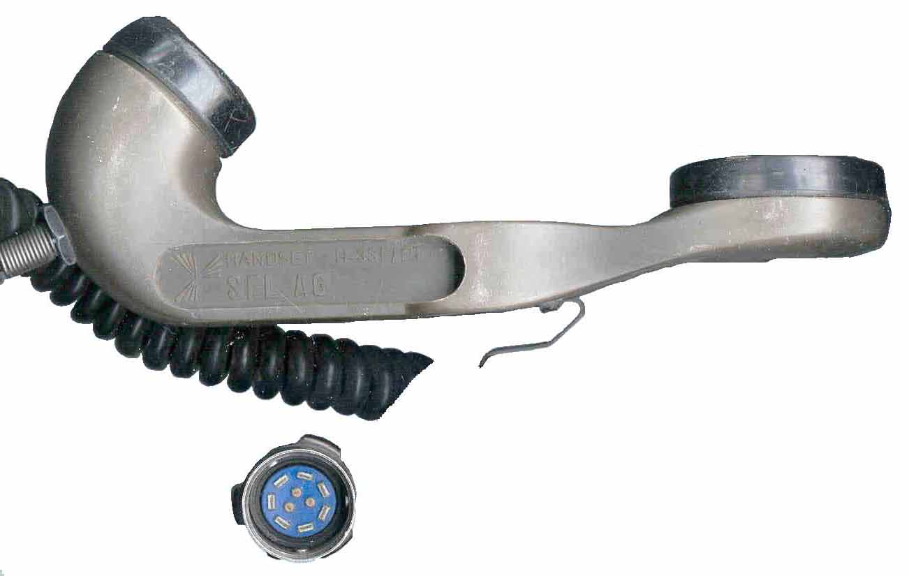
The two 10 pin connectors mate with standard UG-77 audio accessories.
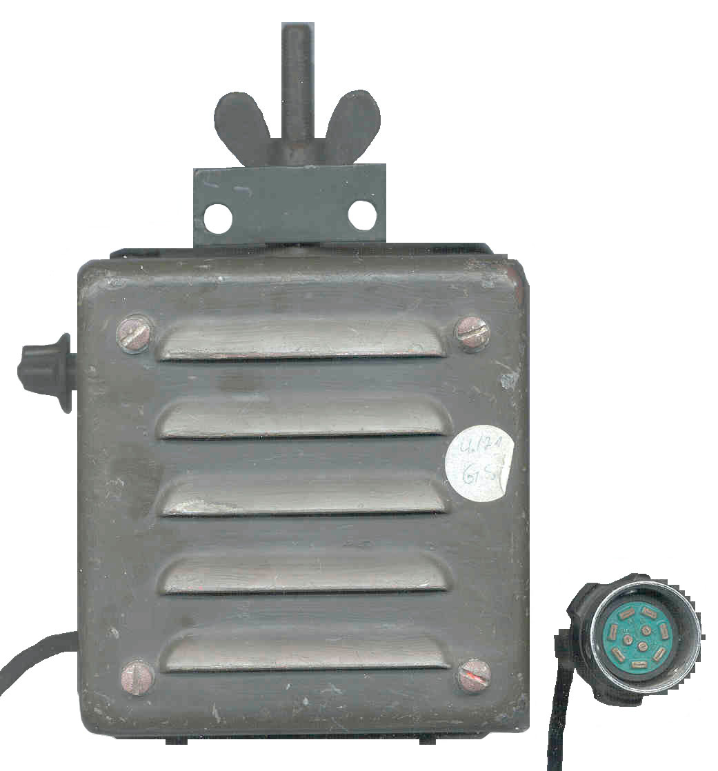
It came with a LS-166 and HT-33 of German manufacture.
The 5805 is what appears to be a NSN refers to Telephone and Telegraph
equipment.
I think this is some type of wire to radio interface probably built
to NATO standards.
To remove the chassis from the carry box just loosen the 4 screws on
the panel a turn or two.
These screws stay with the case and the panel slides out.
You do not need to touch the 8 screws on the inner corners of the carry
box.
The two shield covers come off after removing two screws and sliding
them back.
Then the "U" shaped shield cover slides back and off.
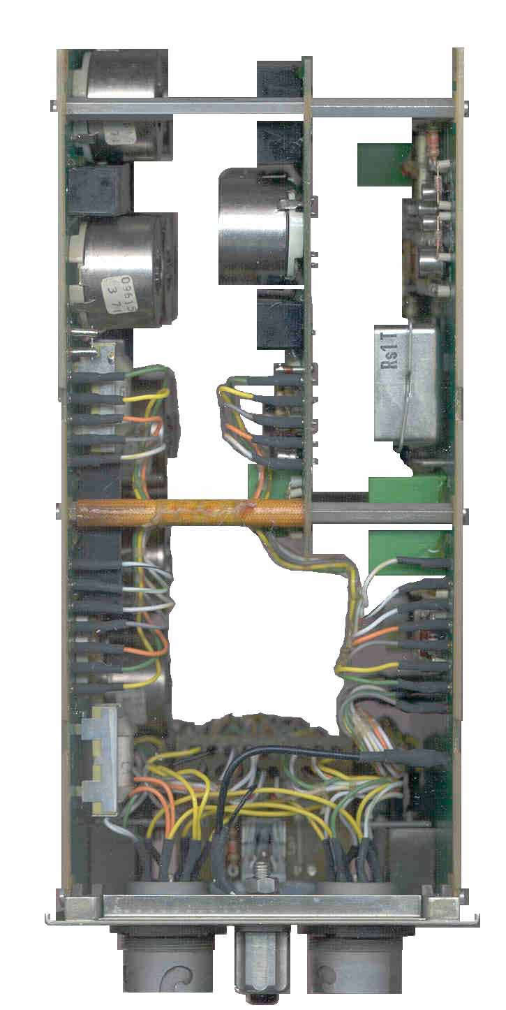
The construction is all discrete components on double sided printed
circuit boards.
There are 12 adjustable pot cores and maybe 24 high Q capacitors, all
for audio frequency filtering.
There are 3 transformers (expected 4 to match the switch on the front
panel).
There is a relay with 16 contacts.
There is a 709 ao amp.
There are 10 transistors.
One ,Ts1, is a TO-5 with a heat sink. Probably a power supply regulator.
It's collector goes to C1+ a electrolitic filter cap.
The 12 socket connectors may be what's called TUCHEL connectors.
The third pin from the top on the left side of each 12-socket connector
is connected to C1- (ground).
The forth pin from the top on the left side of the left connector has
a red wire going to circuit board point 20
that goes through 100 Ohm R1 to the collector of Ts1. Pin 4 of the
left connector may be the 24 VDC input.
The ground lug on the front panel connects to the case but not to any
of the circuitry.
The lamp is rated 24V @ 20 mA.
Both front panel 10-pin connectors are U-79/U and mate with U-77/U
audio accessories.
The standard U-77 pin assignment is:
A - Receiver
Audio
A to A
B - Receiver
Audio Ground B to B
C - Mike
Input
C to C
D -
?
D to D
E - Mike
Ground
E to E
F - Push To
Talk
F to F
H -
Ground
H to H
J - Remote On-Off
no connection
K- CW
Key
no connection
L -
Speaker
L to L
These two audio connectors are wired in parallel.
The Relay Rs1T has 2 each SPDT and 3 each SPST contacts. Pins 1+2 to
one side of the 2.3 K Ohm coil and pins 3 + 4 to the other side.
 |
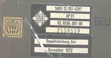 |
| warranty until November 1972 |
 |
|
 |
 |
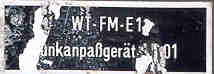
| Front Panel Funk - Draht switch means wire - radio 1, 2 ,3 4 switch chooses a phone pair. |
Inside |
German H-33 handset |
LS-166 |
Back to Brooke's U-229 Audio Accessories, Military Audio, Squad Radio, Military Information, Home page
This is the [an error occurred while processing this directive] time this
page has been accessed since since 7 June 2001.