When I was working in the Electronic
Warfare (
Radar Warning Receivers) business
during the cold war Applied Technology Inc. was the main customer
for
the Limiter Detector that I designed. This test kit may
provide
pinout information for the
ALR-54 LAMPS
RWR
front end. I came with three cable assemblies.
18" wide (probably
rack
mountable) x 10-3/4" high x 4-3/8" deep.
Front Panel Controls, Indicators & Connectors
Power On/Off toggle switch, 28V & 115V pilot lamps, 3 Amp
& 1
Amp fuses.
Disable toggle switches for: AAA, LOW, MID, HIGH
Unblank: B-52/Normal, TDU Intensity Dim/Bright, Prepulse: Radar
2/Off/Radar 1 toggle switches
Audio: Self Test, Pos 1, Pos 2, B-52 EWO, B-52 Remote, APR-26,
Test
Point jack, Volume control.
System: Single, Qualified Dual, Unqualified Dual
Sync Generator: TWS/Con Scan, pots for: Con Scan, TWS Rate. Group
Width, toggle APR-26: Step Test/Normal
J1 test point 16 jack field
J2 test point 22 jack field
J3 test point 12 jack field
ER-142 BNC-f connectors: Low, Mid & High
Sync 1 In (APR-26) BNC-f
Sync 2 In BNC-f
Sync Out:
APR-26, Scope,
APR-25
Loudspeaker on front panel just below Audio controls
Connectors, Side Panels
Jack
|
Description
|
Connector
(suffix = # & sex of terminals)
|
J1
|
Power
|
Deutsch 6733 DS00-7P
|
J2
|
Preamp
|
Deutsch 6729 DS00-61S
|
J3
|
Analyzer J1 & J2
|
Deutsch 6732 DS00-61S |
J4
|
Analyzer J3 |
Deutsch 6739 DS00-37P
|
J5
|
APR-26
|
Deutsch 6733 DS00-12S |
J6
|
EWO
|
Deutsch 6733 DS00-19S |
J7
|
TDU No 1
|
?-6906 DS00-37S
|
J8
|
Ind No 1
|
Deutsch 6733 DS00-12S
|
J9
|
Ind No2 |
Deutsch 6733 DS00-12S |
J10
|
TDU No2 |
Deutsch 6732 DS00-37S |
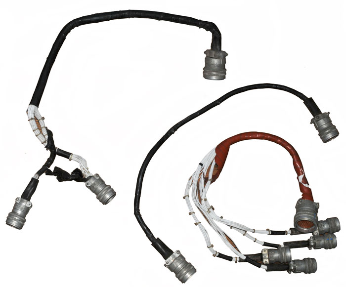
Cables
Preamp
This cable mates with J2 on the
test
set (61 pins) and has four connectors (Front, Back, Left &
Right
side of B-52) on the other end. The four connectors are
all 19
socket Deutsch types.
Analyzer J1 & J1
This cable mates with J3 on the
test
set (61 pins) and has two connectors on the other end for
Analyzer J1
and J2. One has 26 pins and the other has 26 sockets.
Analyzer J3
This cable mates with J4 on the
test
set (37 sockets) and has a 39 pin connector on the other end.
J1 Power Cord
Missing.
[an error occurred while processing this directive] page created 15 Jly
2010.