AN/GRC-109
© Brooke Clarke
2001 - 2017
T-784 (RT-3)
|
R-1004
|
PP-2684
|
PP-2685
|
CN-690
|
|
|
|
|
|
| |
|
G-43 Set eBay photo
 |
 |
 |
|
H-65/U
|
MX-6793
|
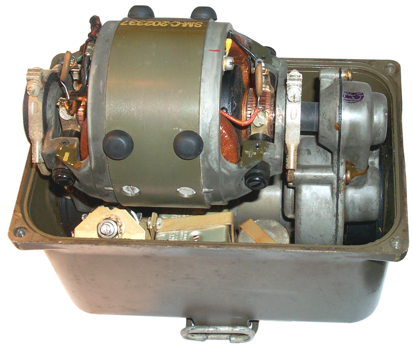
G-43 Generator
|
|
 |
|
|

|
|
GN-
|
|

BG-175 or BG-402?
|
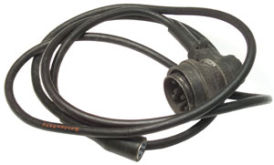
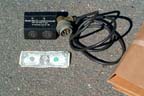
G-43 to PP-2684 Cable
Belden 8424 has 4 ea 20 awg
maybe 6 feet long
|
|
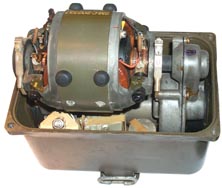
This is a radio set where each major component is built into a
waterproof cast metal housing. This would allow the set to
be stored under ground, under water and retrieved when
needed. Came into being after W.W.II and prior to 1969.
The GRA-71 Code Burst Keyer can
be used with this set after the T-784 has been modified to handle
the high speed Morse code. Note there is no provision to receive
high speed code in the field, only transmit. The idea is to
minimize the time an enemy has to locate the transmission by
minimizing the time to transmission. High speed transmission
is also too fast for a human enemy operator to copy, it requires
recording and playback at slower speed.
Used in Vietnam by forward observers with the GRA-71 burst
transmission device. In this application the radio operator
would only take with him the parts of the system to be used , not
the metal storage boxes and not all the parts. Would like to
know when? before or after 1969. In 1969 U.S. forces
discovered a NVA/VC communications listening post that proved the
NVA/VC could and were using COMINT against us on a scale that no
one imagined.
Note that this radio was not designed to be used while
moving. It's for use in a fixed position.
The PRC-64 (aka CIA Delco 5300) may
also have been one of the radios that replaced the GRC-109.
I've read that the GRC-109 is based on the GRC-9. There is
a resemblance, but not exact match.
|
GRC-9
|
GRC-109
|
Tx Modes
|
CW-AM-MCW
|
CW, HSCW
|
Rx Modes
|
CW-AM-MCW |
CW
|
Tx tubes
|
3A4 3A4
2E22 0C3 3A4
|
6AC7 2E26
|
Rx tubes
|
1L4 1R5
1L4 1R5 1S5 3Q4 1R5
|
1T4 1L4
1T4 1T4 1T4 1U5
|
Adding AM Tx to the GRC-109
This was a question on the Mil Surplus mailing list:
Has anyone tried using the GRC-109
on AM ? I notice its cathode keyed though the osc and
pa are keyed together. I further notice that the 10 pin
keyer socket with its plug shorts the osc and pa cathode
together, so, using another plug one could ground the osc
cathode separately while then cathode modulating the pa.
Also, on the same plug the pa screen volts are accessible, so the
pa could be screen modulated.
Has anyone tried this ? cheers, Ben. G4BXD
The tube line up in the GRC-9 is:
3Q4 Master Oscillator
3A4 Doubler
2E22 P.A.
OC3 Voltage Reg
3A4 Modulator
Maybe the Modulator circuit from the GRC-9 could be added in an
external box?
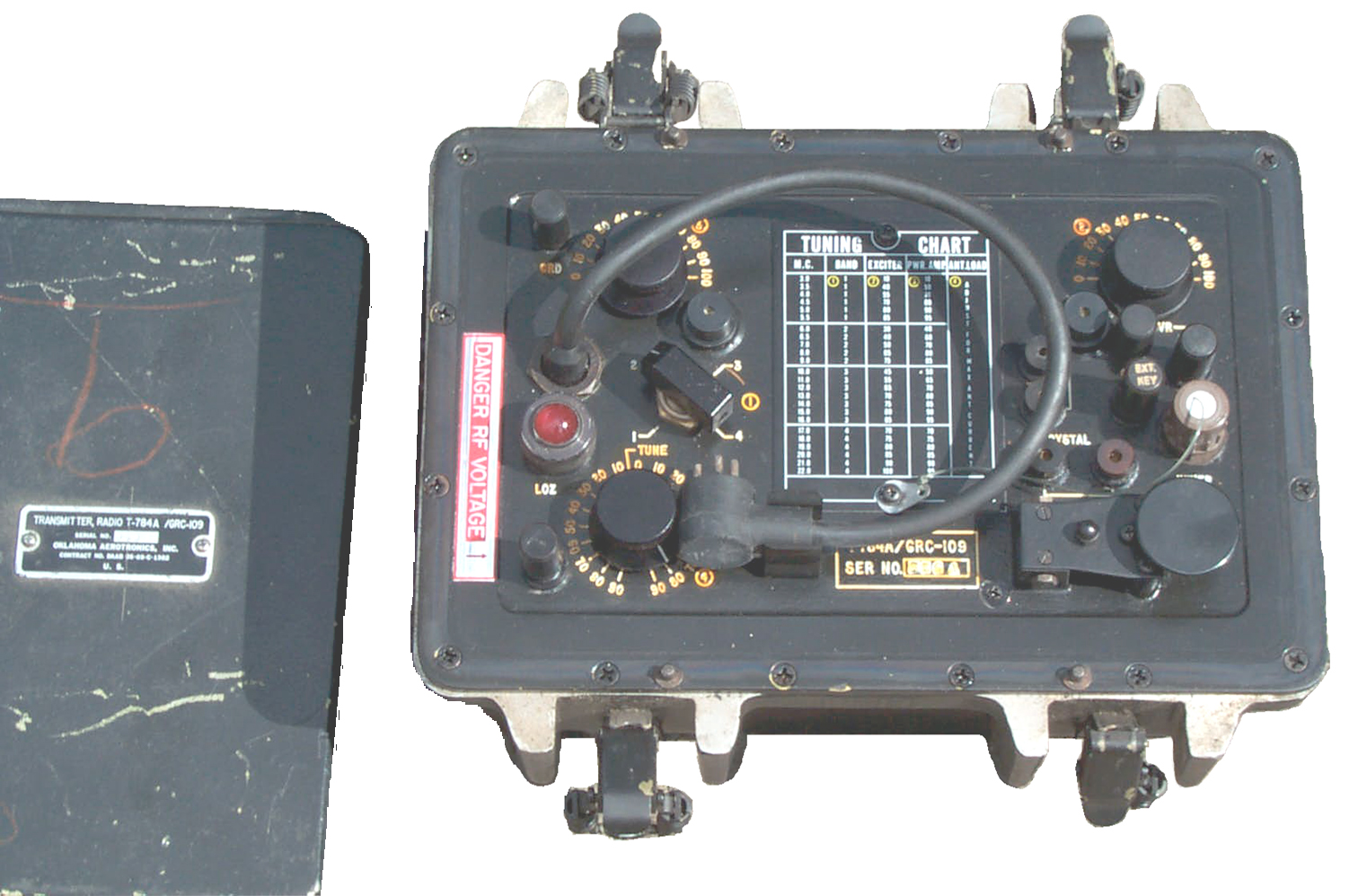
Components of Radio Set AN/GRC-109
Two tube Crystal controlled 3 to 22 MHz with 10 to 15 Watts
output. It's designed to be keyed from the front panel CW
key manually or by plugging in the 300 word per minute GRA-71 high speed keyer. The signal
would be received at a base station with a rack of equipment to
record the message and then play it back at a slower speed.
The oscillator is a crystal controlled 6AC7.
The final tube is the 2E26 Beam
Power Pentode. prf1ss338.pdf
-
The USS
Pampanito (SS-383) has a 2E26 tube somewhere on it and is
origional for a late summer 1945 date.
Gonset 6-Meter
Communicator of the 1950s used the 2E26.
Collins 310 also uses the 2E26 tube ad from Dec
1946
Millen 90810 VHF
Transmitter of late 1940 vintage used the 2E26 as a driver
multiplier.
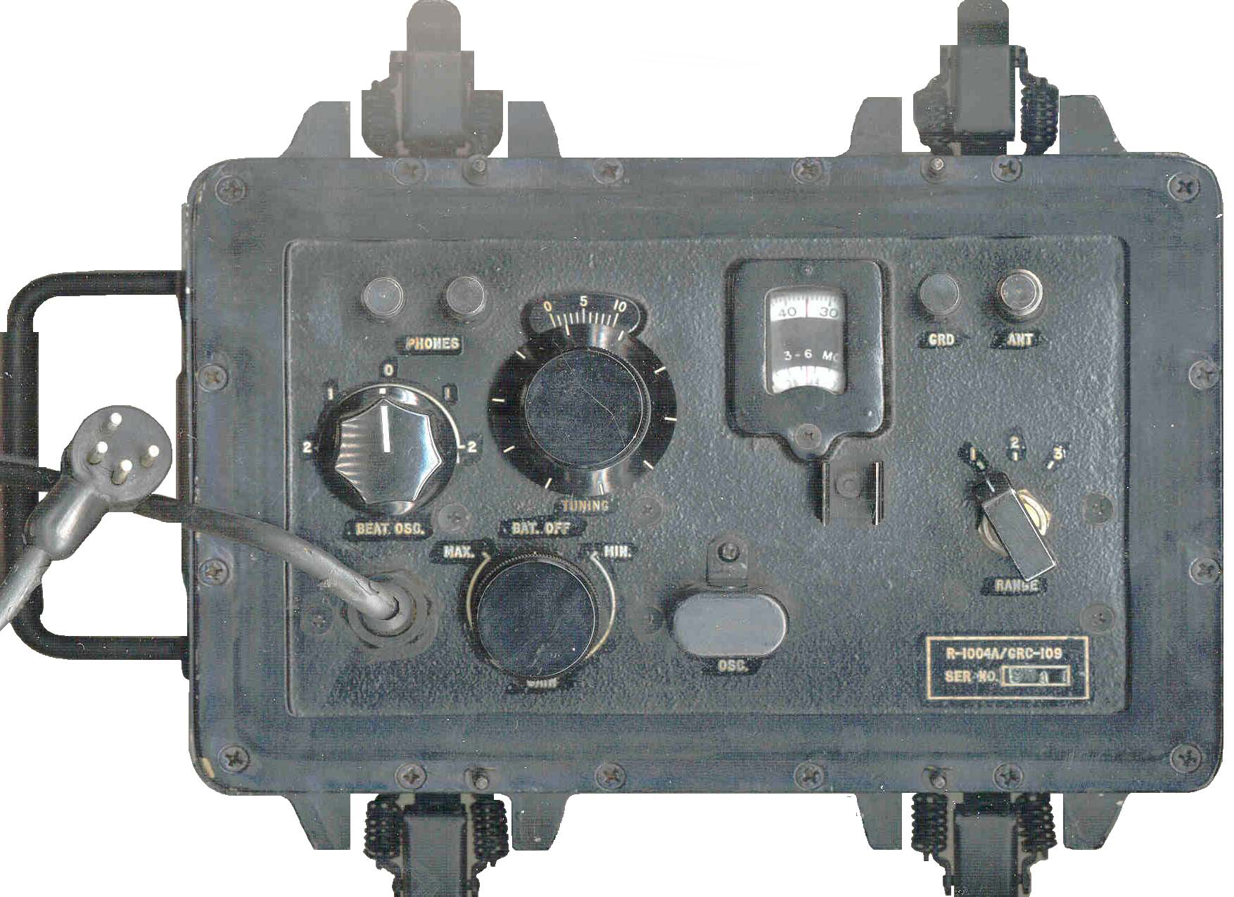
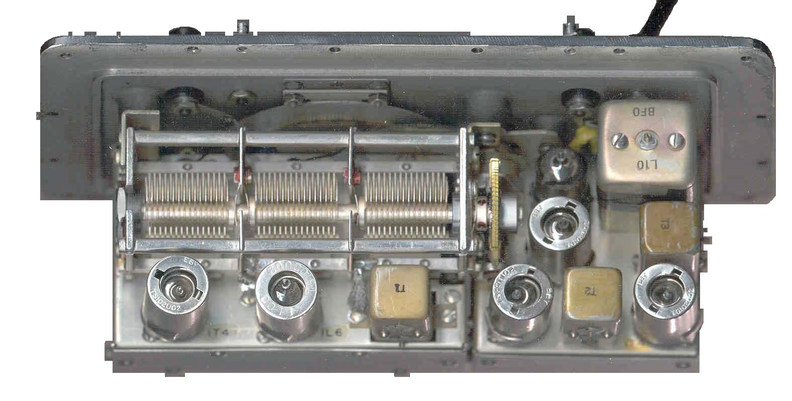
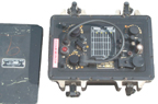
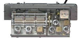
R-1004/GRC-109 Receiver
Superhetrodyne, 3 to 24 MHz coverage in 3 bands. Note
that the receiver is not capable of receiving 300 WPM code.
The receiver appeared to be DOA.
I checked the PP-2685 outputs and they were +1.6 and + 108 VDC
right on the money.
Checked the filaments on all the tubes and they were all in the
7.5 to 10 Ohm range, OK.
Tried again and the receiver was receiving stations without an
antenna when out of it's case.
See Hints & Tips for more about what
goes wrong.
Put in back in and tuned around. Using a B&W 1.8 - 30
antenna and Trimm headphones.
Need to open it up again to lube the tuning mechanism. A
shot of WD-40 after removing the Bat Off knob and the Tuning knob
helped, but it still is tiring to turn these knobs. The WWV
stations are right on frequency.
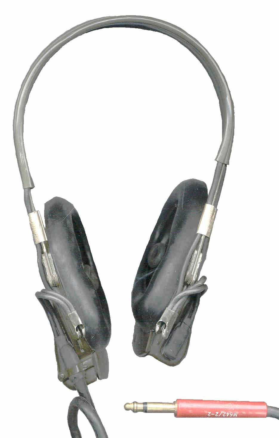
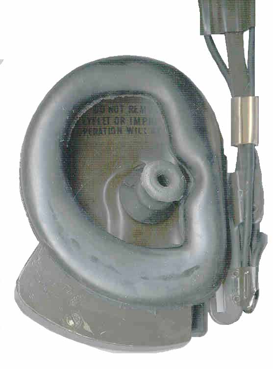
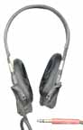
H-65/U headphones are marked 4,000 Ohms
75 to 260 VAC at 40 to 400 cycles -or- 6 VDC -or-
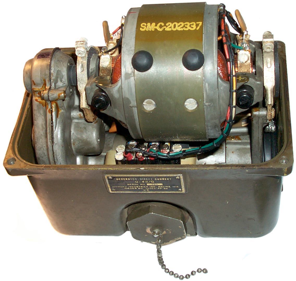
G-43/G generator. Outputs to power T-784, R-1004 and
charge 6 V battery.
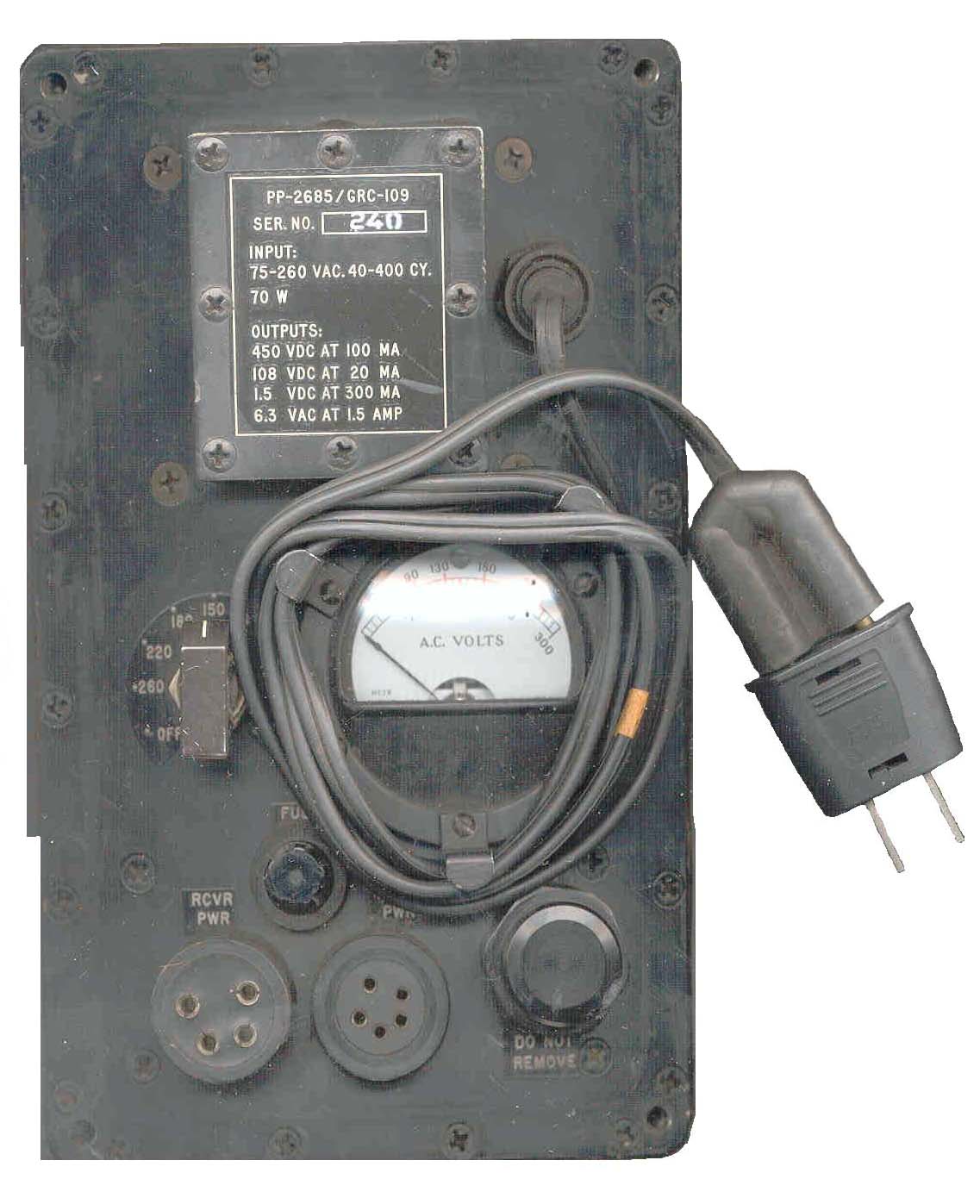
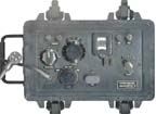
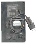
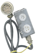
PP-2685/GRC-109 Power Suply
75 to 260 VAC at 40 to 400 cycles. Outputs to
power T-784, R-1004.
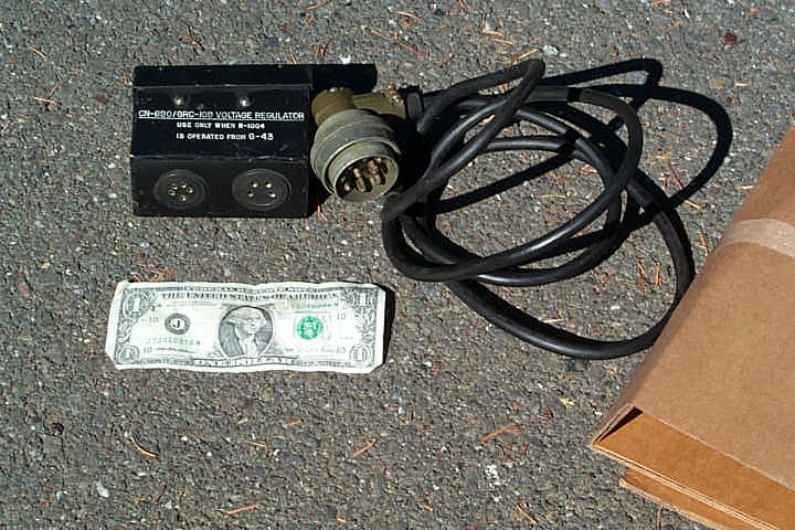
"For use only when R-1004 is operated from G-43"
Uses an OB2 voltage regulator tube and replaces the large power
supply.
The housing has two sockets, see closeup photo above, one for
the receiver and one for the transmitter.
A PL-294 plug with 9 male pins mates to the GN-43.
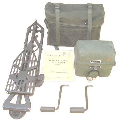
G-43/G Generator (NSN: 6115-00-510-0611)
Used in the 1950 to 1990 time frame.
Manuals:
TM 11-5122
TM-11-6115-218-xx
G-77/G Generator (NSN 6115-01-072-8080)
Used up to 1990.
Manuals:
TM-11-6115-218-xx
Power Supply

G-43/G hand crank Generator-> CN-690 or PP-2684 -> T-784
& R-1004
AC Power Source -> PP-2684 or PP-2685 -> T-784 &
R-1004
6 Volt Battery -> PP-2684 -> T-784 & R-1004
C-43/G hand crank Generator -> T-784
6 Volt Battery -> R-1004
G-43/G Generator
Manual
TM-11-51 22 May 1957
C1 25 Sep 1961
C2
C3 4 Nov 1963
C4 24 Apr 1967
C5 10 Dec 1973
C6 3 Aug 197
Operation Accessories
Technical Manuals:
TM 11-5820-474-14 (ETM 018757.pdf, 36 MB)
Operator's Organizational, Direct Support, and General
Support Maintenance Manual
The -14 manual on ETM has changes through 6 and
includes testing procedures through fourth echelon.
It also has "A" size schematics for each of the component
parts shown above.
Earlier manuals were Operator, Organizational, and Field
Support.
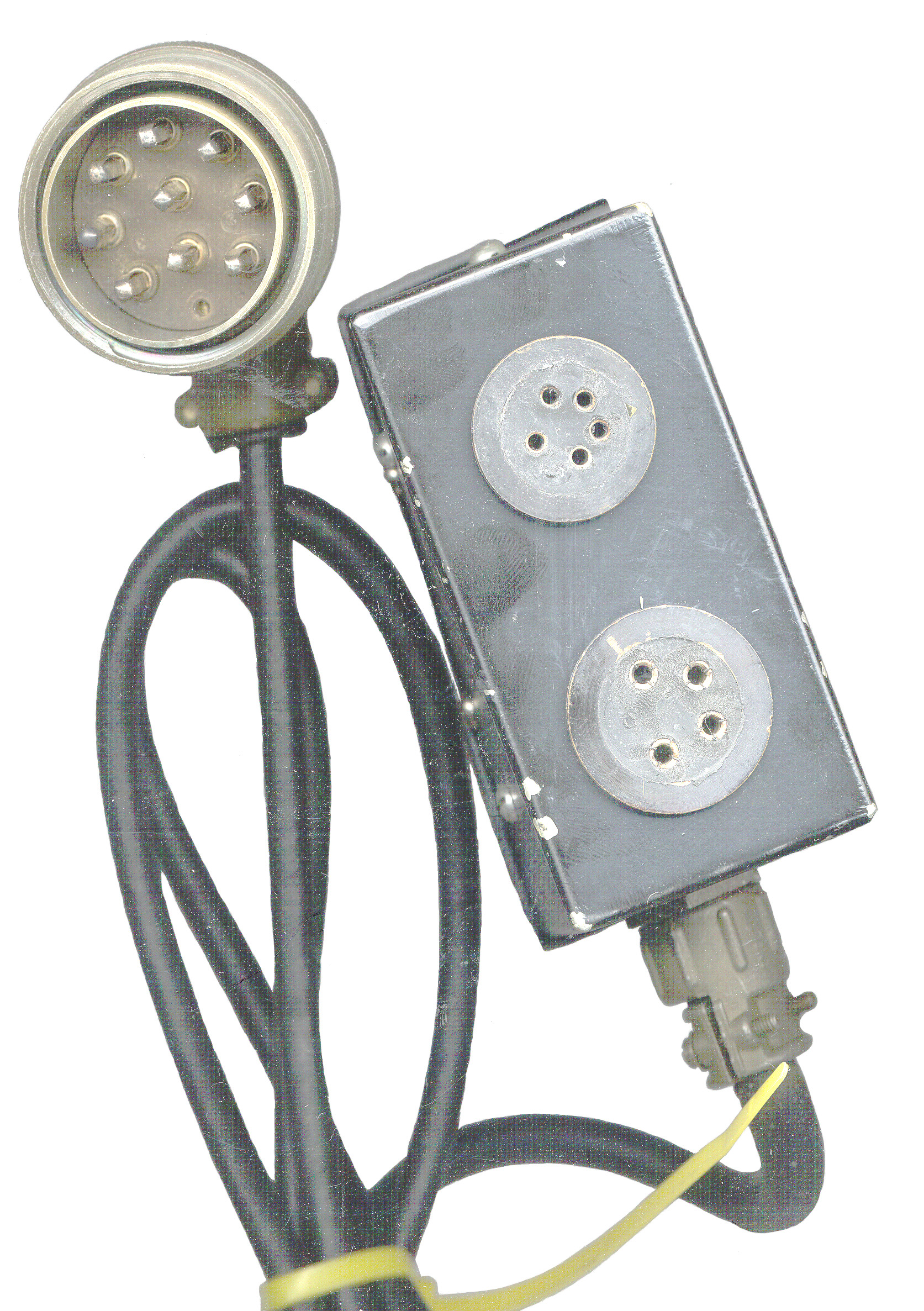
CN-690/GRC-109 Voltage Regulator
No. 18 wire, 100'
AS-1722/GRC-109 Antenna
CX-11042/GRC-109 electrical power cable assembly
CX-11041 Special Purpose cable assembly
MK-833/GRC-109 Maintenance Kit
MX-6792/GRC-109 Adapter, lamp holder
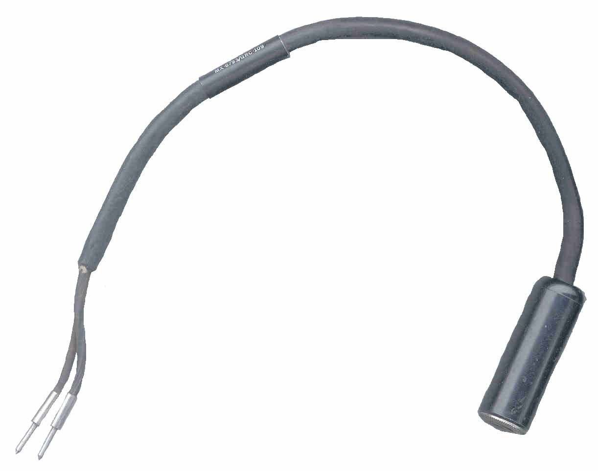
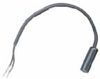
MX-6793/GRC-109 adapter, headset (from 1/4" mono phone socket
to tip plugs)
CY-4621/GRC-109 case
clamp, electrical ground
connector, adapter (lamp base)
TL-29 knife
Pliers, ling-nosed
screwdriver
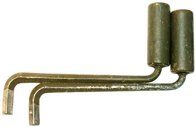
wrench, open end
wrench, Allen No 8
Running Spares
OB2 tube
1L6 tube
1T4 tube
1U5WA tube
2E26 tube
6AC7 tube
3AG 2-amp fuse
3AG 15-amp fuse
white porcelain insulators (antenna egg style)
GE 47 lamp
6-volt vibrator
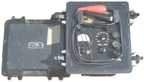
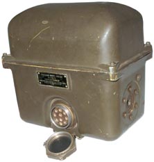
Transit Case - photo from
eBay
Generator Set, Gasoline Engine, 0.125-KW, 115-Volt,
Single-Phase, 400-Cycle, Special-Purpose, Portable, with
Carrying Case, Model UGP-12
MIL-G-52368A(1)
Internal T/R Switch Problem
From Milsurplus list server
Date: Wed, 15 Feb 2006 10:16:51 -0800
From: "Kenneth G. Gordon"
Subject: Re: [Milsurplus] GRC-109, RS-1 transmitter - keying
On 15 Feb 2006 at 11:54, B. Smith wrote:
> Has
anyone
modified the Transmit Receive (TR) circuit for the T-784(GRC-109 or RT-3 (RS-1)
to improve receiver sensitivity when using the internal automatic
antenna switch between transmit and receive?
I have.
> is
keyed.
The problem is that there are extreme loses in the receive side of the TR circuit
due to the receiver coupling capacitor
C14
which is only 18 pf but is in the output circuit of the transmitter.
No. That isn't the problem: the problem is called "suck-out" and
is caused by the transmitter's final tank circuit being tuned to
the same frequency as the receiver's input circuitry. One of the
list members on the Glowbugs list calculated the losses due to the
final tank circuit being connected effectively in parallel or
series (I have forgotten which) with the receiver's input
circuitry, and it amounts to -30DB LOSS!!! in the case of the
GRC-109.
Suck-out was a common problem for hams who used TR switches which
were connected directly to the final amp's tank circuitry.
> The
receiver
sensitivity loss is paraphrased in TM-11-5820-474-14, Chapter two, 14e, under
"Preliminary Connections, Separate Transmitting and Receiving
Antennas."
Yes, but it doesn't tell you why: it is "suck-out", period. The
receiver coupling cap is plenty big enough to do the job.
> In
Vietnam
at base camps the sets were used with separate antennas.
Yes, and that method was suggested in the manual too. The internal
TR switch was only to be used in an emergency.
> I
have been using an external antenna change over switch for the
set to prevent the
receive loses but I am preparing to modify the set
> using either pin
diodes (ugh) or a small relay.
:-)
There are several ways you can do it: what I did was
non-destructive. I mounted one of those small 5 VDC Radio Shack
relays internally on a bit of double-sided tape, and used a single
diode to rectify the filament voltage as a 1/2 wave rectifier. I
oriented the diode in such a way that if you used 6 VDC on the
filaments, the diode would pass that voltage on to the relay so
the circuit works the same way whether you are using AC or DC.
I use the relay to both key the rig and change the antenna so that
QSK is preserved. It easily follows my bug at 20 WPM or more.
It works very well.
Or you could build an external TR box that does all that.
Electric Radio mag recently had an article on just that subject.
BTW, I REALLY like the AN/GRC-109. It even runs off my PE-162C
generator, although I have not yet gotten my DY-88 to work with
it. My GN-58 does a superb job with it, especially since I mounted
the GN-58 to an old exercise bicycle. I can even send while
pedaling.
:-)
Ken W7EKB
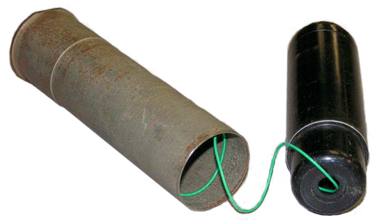
40 mm Grenade Antenna
Is anyone familiar with a
40 mm grenade launcher cartridge intended
for use with the GRC-109 radio? (
let me
know) It was intended to be fired in an
M79 grenade launcher. The projectile
is a black anodized aluminum cylinder filled with green plastic
insulated antenna wire that pays out in flight. One end of the
wire was attached to the heavy steel cartridge case and the other
in the projectile. When the cartridge is fired, the projectile was
supposed to penetrate through the jungle canopy and leave the wire
hanging in the treetops. The other end remained attached to the
fired case, and when unloaded from the M79, could be cut off and
attached to the radio.
I've seen three of these over the years and
the one in my collection is marked (in felt pen) for SEAL
and SF use with GRC-103 radio (220 - 1850 MHz). I believe
this is incorrect and was actually intended for the
GRC-109. One example I've examined was a cutaway
that came from the manufacturer, AAI Corp., via a retired
engineer. The other was at the EOD unit at Camp Pendelton
about 20 years ago.
So I know they existed but don't know how extensively they
were used or if they are documented anywhere in the
literature for the radios themselves. Are any of you spy
radio enthusiasts familiar with this device?
I'll take a couple photos and post them if anyone would
like to see it. Thanks. Rick |
Links
William L.
Howard Technical Museum - Spy
Radios
of
WWII - "With the end of the war, these sets seem to have
disappeared. The OSS was disbanded and in 1947 it's successor, the
Central Intelligence Agency was established. The first set adopted
by the CIA was the RS 1 which bears no resemblance to the SSTR 5
or the SSTR 1. The RS 1 was adopted by the military, with some
modifications and designated as the AN/GRC 109 . . ."
Modifying
HC-6 crystals to have larger diameter pins like an FT-243 so
they can be used in the T-784 transmitter, Done be soldering
an octal tube pin onto the crystal wire lead.
FM
24-24
Chapt
4 -
GRC-109
by Peter
McCollum
Antique Radios - Solid State
Replacement for the 1L6 - eBay seller
-
CIA Documents
Preliminary
Instruction Manual for Radio Set AS-3 February 11, 1959
-
Technical
Notes on AT-3 Transmitter August 26, 1960 -
AT-3
Photo - poor quality B&W
Engineering/Operational
Base Station Automatic Alarm - December 11, 1961 - use
the 150 Hz IDY signal that's part of the tape preamble as a signal
- maybe the beginning of the "New Squelch" on VHF low band radios
like the PRC-25
The
RT/A-3 Transmitter, a part of the BN-2
RS-6 Spy Radio
This is a similar radio from the early 1950s. These are photos
from eBay.
RA-6 - Power Supply Filter
RP-6 - Power Supply
RR-6 - Receiver, 3-15Mhz in two bands 8
subminiature tubes
RT-6 - Transmitter, CW only, 3 - 16.5
Mhz, 2 tubes 6-10W 2E26 final
Instruction
Book for Radio Station RS-6
Strategic Service
Transmitter-Receiver Number I (SSTR-1) - (0:22:29)
Back to Brooke's Products
for Sale, PRC68
Family Radios, Military Information,
Crypto, GRA-71,
Home page
Page created 27 July 2001