MSC2001 Voice Encryption Unit (VEU)
© Brooke Clarke, N6GCE 2004 - 2022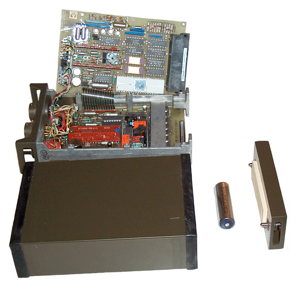 |
 |
 |
Background
Construction
Connector Pinouts
DC Power
A58 Module (aka VEU-2001)
Testing
Links
Construction
Connector Pinouts
DC Power
A58 Module (aka VEU-2001)
Testing
Links
Background
As far as I know, no one has got
a pair of these surplus units to operate.
This is another voice security
device used with radios like the PRC-77.
This
box has an identical function as the KYV-2,
KY-38 or KY-57
Transmission Encryption Devices, although it uses a different
algorithm.
In order to use it two things need to be accomplished:
(1) a key needs to be loaded into one or more of the 8 slots.
In order to use it two things need to be accomplished:
(1) a key needs to be loaded into one or more of the 8 slots.
There are a number of key loaders for the U.S. crypto boxes including the CV-4228 PC to SINCGARS fill cable. This fill cable uses the RTS and DTR lines to generate the Clock and Data streams (NOT the transmit data line which has no clock). This method is much simpler in terms of hardware, but more complex in terms of software than building a custom key loader for the MSC-2001.(2) an interface needs to be used between the MSC-2001 and the radio.
A very simple cable could be made by wiring the RS-232 outputs from RTS and DTR directly to the clock and data pins on the MSC-2001. No active parts are required and the same software that drives the CV-4228 could be used.
Vehicle
The KY-57 is used with the J-3513 Junction Box that interconnects the KY-57, radio, DC power supply, and Vehicle Inter Communication (VIC) equipment or wire line adapters. The J-3513 (or the smaller J-3514) might also work as the interface between the MSC-2001 and the rest of the system?
Manpack
It may be that just a cable could be used between the MSC-2001 and a PRC-77, like the CX-12991/U between the KY-57 and PRC-77. The pin assignments on the MSC-2001 strongly suggest this is the case. Although the cable is NOT a 1 to 1, it's close.
Construction
This is the model S42043-E9-B104 with a code selection switch.
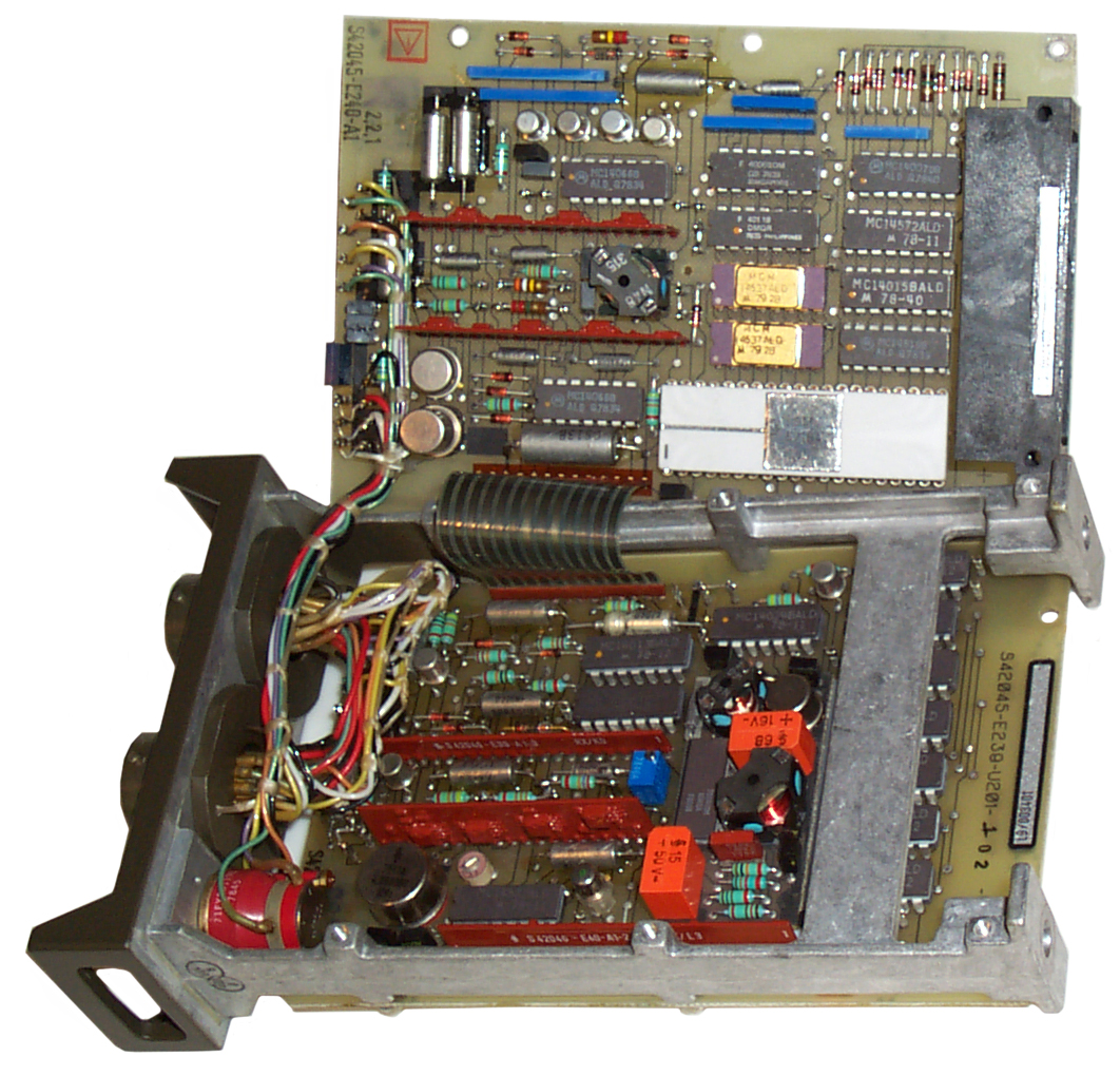
There are two main printed
circuit boards using through hole components. The boards
appear to be double sided with the bottom traces generally
going left to right and the top traces going up to down.
A 40 pin IC (probably a micro processor) is in a socket formed
using 40 individual sockets. Nearby are what appear to
be a couple of ROM chips.
There's also 5 daughter printed circuit boards which use surface mount technology and have been painted red. Four of these red boards have 3 or 4 each ICs with 6 leads, most likely op amps. None of them have any higher pin count chips so they most likely are analog processing.
Another larger daughter board has a couple of pot core type inductors/transformers and has the feel of a switching mode power supply. It has a 74S40 Switching Mode Power Supply controller IC rated at 1.5 Amps and 100 kHz.
There's a couple of green wire wrap wires soldered to the bottom of one of the printed circuit boards indicating a "fix" was needed.
The 3.4 Volt "AA" size battery in this unused unit was completely dead (0.0 Volts).
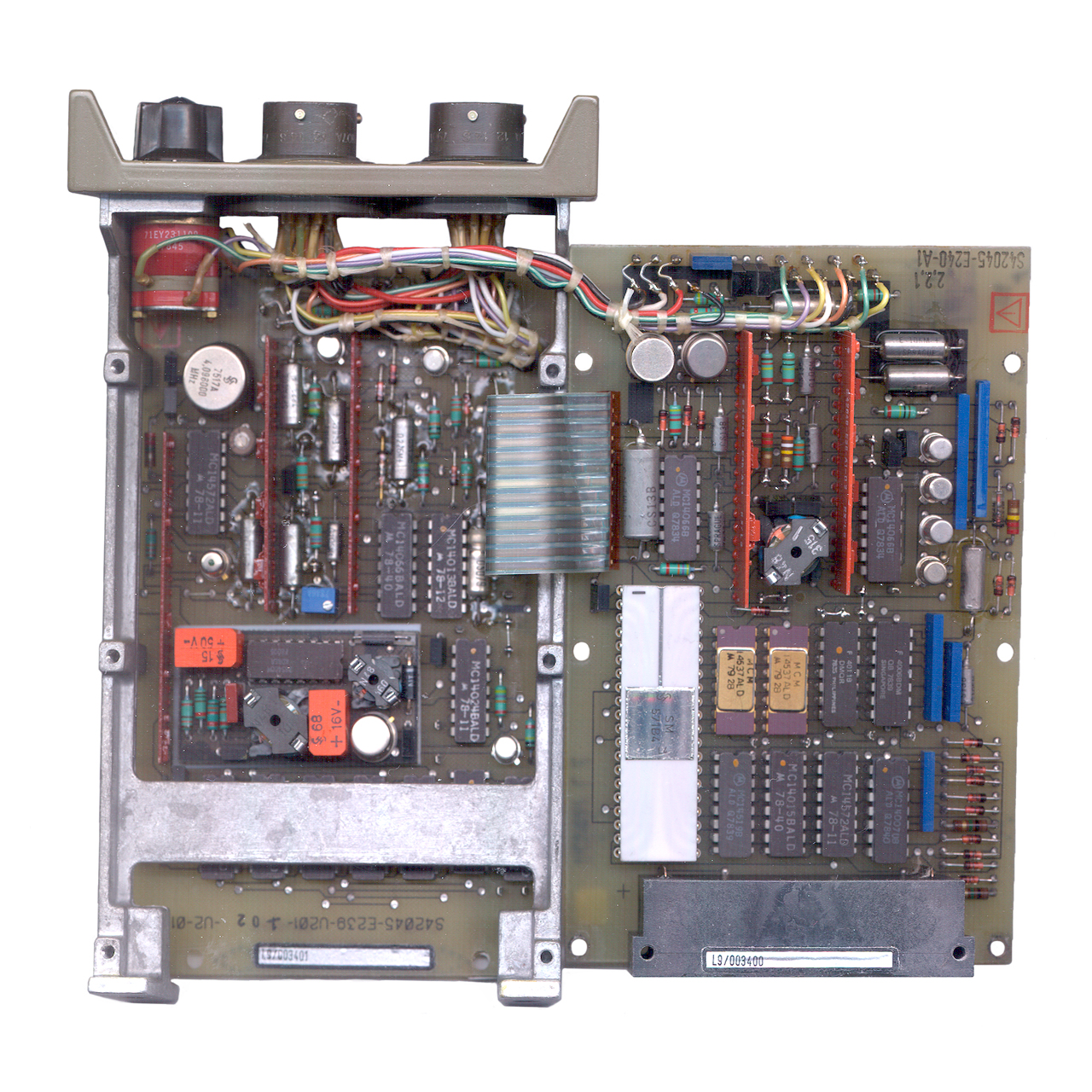
There's a lot of 14 pin 14xxx series CMOS ICs: MC14001 Quad 2-Input NOR gate, MC14013 Dual Type D Flip-Flop, MC14015 Dual 4-Bit Shift Register, MC14024 7-Stage Ripple Counter, MC14025 Triple 3-Input NOR Gate, MC14035 4-Bit Parallel-In/Parallel-Out Shift Register, MC14066 Quad Analog Switch, MC14070 Quad XOR and NOR Gates, MC14519 4-Bit AND/OR Selector or Quad XOR, MC14572 Hex Gate, and some other chips near the 40 pin IC.
There are two connectors, both of which are the same as the POWER connector on a PRC-77 radio. One is labeled REMOTE and may be used in an aircraft installation to control the MODE selection of which code to use. The other connector is marked TX/RX and is the interface to the PRC-77 or other wide band radio. The REMOTE connector is also used for loading up to 8 keys.
The Tx/Rx connector has the following pins connected to the same letter pin on the REMOTE connector: A, B, C, D, E, F, J. On my unit with the front panel switch, I see no way the REMOTE connector can control the channel selection. Maybe it does on the other version. The REMOTE does have the key load connections which are not on the TX/RX connector.
The MODE switch has 8 channel positions for different keys plus positions for CLEAR speech and CODE ERASE. The switch has no mechanical stops and can be turned completely in a circle. There's a thin plastic disk on the switch shaft under the knob that has a pointer sticking out past the diameter of the knob. If the switch is turned either clockwise or counterclockwise to the CODE ERASE position the thin plastic disk breaks into two pieces. If this happens you can use acrylic cement (solvent) to fix the disk.
The 10 position Grayhill - Series 71 (marked on back 81073) switch has only 5 wires connecting it to the rest of the MSC-2001. This is a 1, 2, 4, 8 binary switch. The black wire is ground, Violet is 1, Orange is 2, Yellow is 4, and Green is 8. Decimal position 0 is labeled 1, position 7 is labeled 8, position 8 is labeled CLEAR and position 9 is labeled CODE ERASE.
There's also 5 daughter printed circuit boards which use surface mount technology and have been painted red. Four of these red boards have 3 or 4 each ICs with 6 leads, most likely op amps. None of them have any higher pin count chips so they most likely are analog processing.
Another larger daughter board has a couple of pot core type inductors/transformers and has the feel of a switching mode power supply. It has a 74S40 Switching Mode Power Supply controller IC rated at 1.5 Amps and 100 kHz.
There's a couple of green wire wrap wires soldered to the bottom of one of the printed circuit boards indicating a "fix" was needed.
The 3.4 Volt "AA" size battery in this unused unit was completely dead (0.0 Volts).
There's a lot of 14 pin 14xxx series CMOS ICs: MC14001 Quad 2-Input NOR gate, MC14013 Dual Type D Flip-Flop, MC14015 Dual 4-Bit Shift Register, MC14024 7-Stage Ripple Counter, MC14025 Triple 3-Input NOR Gate, MC14035 4-Bit Parallel-In/Parallel-Out Shift Register, MC14066 Quad Analog Switch, MC14070 Quad XOR and NOR Gates, MC14519 4-Bit AND/OR Selector or Quad XOR, MC14572 Hex Gate, and some other chips near the 40 pin IC.
There are two connectors, both of which are the same as the POWER connector on a PRC-77 radio. One is labeled REMOTE and may be used in an aircraft installation to control the MODE selection of which code to use. The other connector is marked TX/RX and is the interface to the PRC-77 or other wide band radio. The REMOTE connector is also used for loading up to 8 keys.
The Tx/Rx connector has the following pins connected to the same letter pin on the REMOTE connector: A, B, C, D, E, F, J. On my unit with the front panel switch, I see no way the REMOTE connector can control the channel selection. Maybe it does on the other version. The REMOTE does have the key load connections which are not on the TX/RX connector.
The MODE switch has 8 channel positions for different keys plus positions for CLEAR speech and CODE ERASE. The switch has no mechanical stops and can be turned completely in a circle. There's a thin plastic disk on the switch shaft under the knob that has a pointer sticking out past the diameter of the knob. If the switch is turned either clockwise or counterclockwise to the CODE ERASE position the thin plastic disk breaks into two pieces. If this happens you can use acrylic cement (solvent) to fix the disk.
The 10 position Grayhill - Series 71 (marked on back 81073) switch has only 5 wires connecting it to the rest of the MSC-2001. This is a 1, 2, 4, 8 binary switch. The black wire is ground, Violet is 1, Orange is 2, Yellow is 4, and Green is 8. Decimal position 0 is labeled 1, position 7 is labeled 8, position 8 is labeled CLEAR and position 9 is labeled CODE ERASE.
Connectors
There are 2 connectors on the
MSC2001 one labeled Tx/Rx used for the radio interface and one
labeled Remote that's used for either key loading or for
connection to other equipment, like the AM-2060 or the MK-456 retransmission kit.
This table is my best guess as to what the pinout is. You can see the MSC2001 was designed with the PRC-77 in mind.
Note 1 - Both "N" pins are DC inputs that are joined by diodes
so either one will power the MSC2001, yet the DC can not be
fed from either.
This table is my best guess as to what the pinout is. You can see the MSC2001 was designed with the PRC-77 in mind.
| Pin |
H-250 |
PRC-77 |
MSC2001 Tx/Rx |
Linked |
MSC2001 Remote |
| A |
Gnd |
Gnd |
Gnd |
= |
Gnd |
| B |
spkr |
Aud
out |
Aud out | = |
Aud out |
| C |
PTT |
PTT |
PTT |
= |
PTT |
| D |
Mike |
Aud
in |
Aud in | = |
Aud in |
| E |
- |
+15
in |
+15 in | = |
+15 in |
| F |
- |
Batt
+15 |
Batt +15 | = |
Batt +15 |
| H |
- |
nc |
PTT? |
= |
key
CTS in |
| J |
- |
Mike
gnd |
Mike gnd | = |
Mike gnd |
| K |
- |
retrans
PTT |
nc |
x |
-9
out |
| L |
- |
tone
dsbl in |
tone dsbl in | x |
key
clock in |
| M |
- |
nc |
Aud
out |
x |
key
RTS out |
| N |
- |
sw
+10 out |
+12 in | Note
1 |
+12
in |
| P |
- |
Rx-X-out |
X
out |
x |
key
data in |
| R |
- |
Tx-X-in |
X
in |
x |
key
RTS in |
DC Power
Main
Main "12 Volt" power is supplied
through either of the connectors. Power on-off is
handled by external wiring. With my home made Tx/Rx
cable power is supplied to the MSC-2001 when the PRC-77 is
switched on.
PRC-77 pin "N" is switched 12 Volt power. There is no direct connection between the MSC-2001 REMOTE pin "N" an the Tx/Rx pin "N". But they both feed through a diode "OR' to the power MSC-2001 supply so either one will power the MSC-2001.
Pins "E" (12 Volts into PRC-77) and "F" 12 Volts from battery are straight through from Tx/Rx to REMOTE, allowing power for the PRC-77 to be feed through the MSC-2001, like when the MSC-2001 is connected in series from the SET POWER jack on the AM-2060A to the MSC-2001 REMOTE connector and then from the MSC-2001 Rx/Tx connector to the PRC-77 POWER connector.
A58 Module (aka VEU-2001)
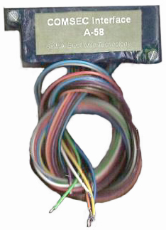 An eBay seller offered an "A-58 COMSEC
Interface" module for the PRC-77 that has 11 wires. This
module is needed when the MSC2001 is used with the PRC-77.
An eBay seller offered an "A-58 COMSEC
Interface" module for the PRC-77 that has 11 wires. This
module is needed when the MSC2001 is used with the PRC-77.Wiring Pinout
| Wire |
Destination |
| Gray |
A-57
pin 2 |
| White |
A-57
pin 3A close to pin 3 |
| Violet |
A-57
3B other side of gap that needs to be cut in trace 3 |
| Black |
A-57
pin 6 |
| Blue |
A-57
pin 12 |
| Orange |
A-57
pin 15 |
| Green |
unsolder
wire
from J3-C & connect Green wire here |
| Brown |
to
wire removed above |
| White/Black |
J3
pin H |
| Blue/Black |
J3
pin M |
| Red |
K2
relay pin 1 |
Power jumper plug MWO
Remove jumpers between H, L, and M (the PRC-25 3 volt jumpers) but leave the E to F 14 volt jumper.
Hold Up Battery
The Hold Up
Battery (HUB) is the same 3+ Volt "AA" size as used in the PLGR.
Testing
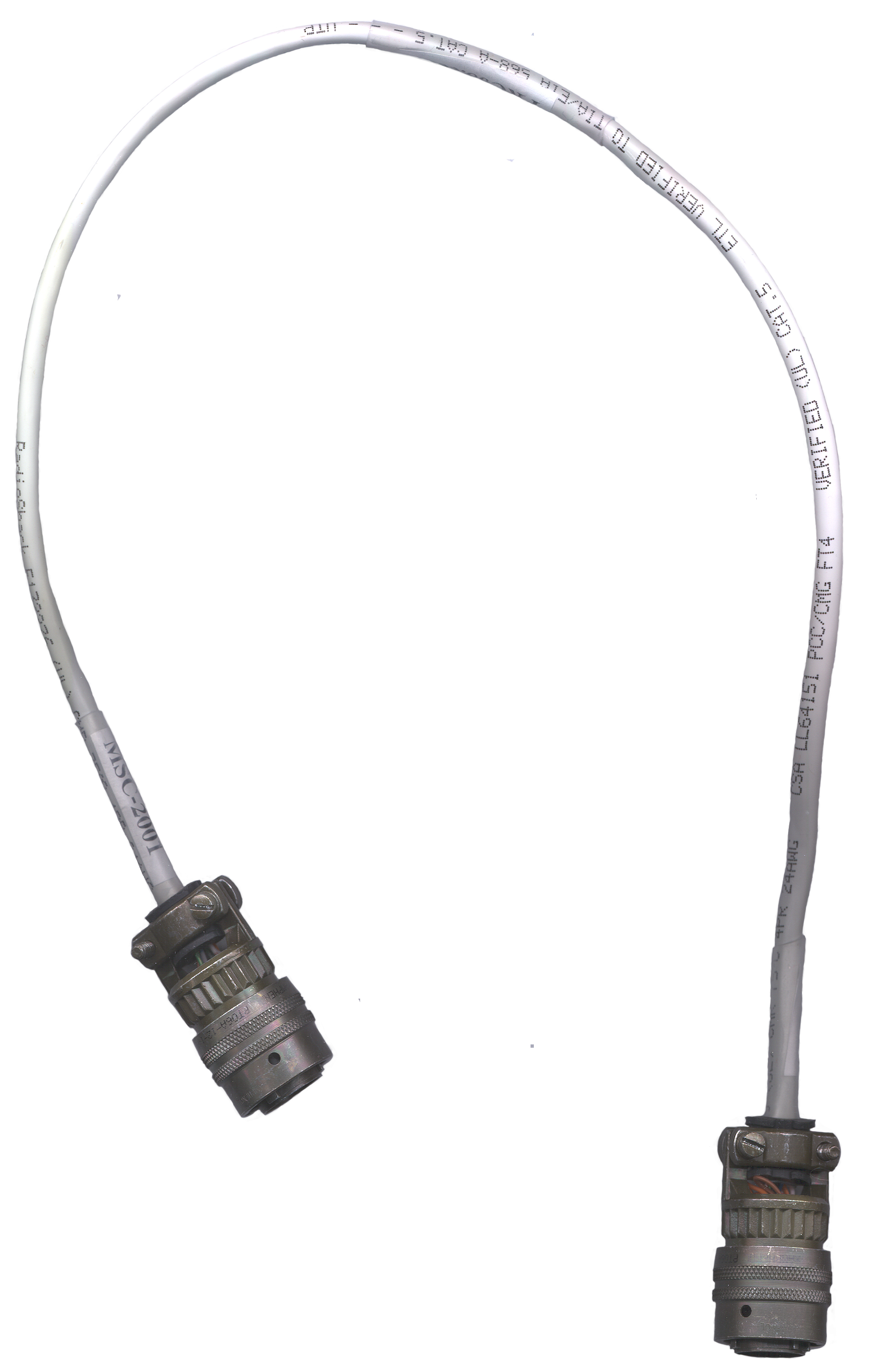 7 May 2004 - Connected home made
cable between the MSC-2001 and a PRC-77 with a 257477BA Battery Adapter to power
the PRC-77 and MSC-2001. With the mode switch on any of
the 8 key slots the H-250 handset connected to the PRC-77 sounds
like a telephone busy tone, indicating no key loaded. With
the MODE switch set to CLEAR the handset hears noise on receive
and on transmit a carrier is sent, but no modulation sometimes
and others a squealing tone is transmitted and heard in the
handset. Done with no HUB battery installed. The cable
includes a jumper to disable the 150 Hz tone, which is the
common thing done with voice security devices.
7 May 2004 - Connected home made
cable between the MSC-2001 and a PRC-77 with a 257477BA Battery Adapter to power
the PRC-77 and MSC-2001. With the mode switch on any of
the 8 key slots the H-250 handset connected to the PRC-77 sounds
like a telephone busy tone, indicating no key loaded. With
the MODE switch set to CLEAR the handset hears noise on receive
and on transmit a carrier is sent, but no modulation sometimes
and others a squealing tone is transmitted and heard in the
handset. Done with no HUB battery installed. The cable
includes a jumper to disable the 150 Hz tone, which is the
common thing done with voice security devices.