M1913 Sketch Set, Surveying, Military Field Sketching

© Brooke Clarke 2010 - 2011

Photos
Background
ID Info
Manual
    Hand Receipt
Set Layout
Misc
Related Web Pages
Links

Sketch Set,
              Surveying, Military Field Sketching
Sketch Set, Surveying, Military Field
              Sketching
It may be that this set was used for some nighttime ops and was painted black in the field.  Maybe also "U.S. Sketching Board Model 1913" was taken off using paint remover?
M1913 Sketch Set, Surveying, Military
              Field Sketching
Glow in the dark compass, paper hold downs with 6-40 threads (why that pitch?)
The paper goes between the round shiny pin and the bottom of the hold down top.
M1913 Sketch Set, Surveying, Military
              Field Sketching
Board photo by S.H. showing U.S. Sketching Board Model 1913
Sketch Set, Surveying, Military Field
              Sketching
One of the Velcor strips has come unglued from the bottom of the table and can be seen here stuck to the lower right corner of the cover.
Sketch Set, Surveying, Military Field
              Sketching

Sketch Set, Surveying, Military Field
              Sketching Sketch Set, Surveying, Military Field
              Sketching
17" wide by 16" high by 4 1/2" thick
11 pounds

Background

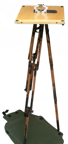
This is a military Sketch Set that's designed to be field portable.  The set is an example of Plane Table Surveying.  This method was the official way the U.S.G.S. made maps for many decades and is old enough that there are plenty of free books on line that describe the methods (see Links below).  Most any good book on surveying will have a chapter on plane table work.

The typical setup is to level the table then orient it so the top is facing North (true is preferred, but magnetic will do if so noted).  Any device that allows sighting to a landscape feature (called an alidade) allows drawing a line from a point on the paper that's your current location through the feature.  Note that the exact bearing of the board/paper is not too important since the lines to the features are correct in a relative sense.

If you have a way to determine the distance to the feature then it can be scaled and marked as a point on the paper.  The method of stadia can be used with a telescope that has the required reticule.  This may be either a surveying instrument or a rifle scope.  A laser or optical range finder would also be a modern way to get the distance to a distant object.

If you don't have a way to get the distance then each feature line can be labeled in pencil with the feature name.  One of the feature lines is to (or from) the new table location.  The distance between the two table locations needs to be established so the new location can be added to the paper as a point.  Now sighting the same features as before and drawing a line to them from the new point of table location results in locating each visible feature as a point at which time the construction lines can be erased.

Feb 2011 email from Brian Haren (Blog)

"As background, I am a retired Army Corps of Engineers officer and spent most of my time in the Topographic field managing surveying, mapping and terrain analysis (military geography) efforts around the world.  I am very familiar with the M1913 Sketch Set as it remained in our MTOE authorizations into the 1980s.  In my assignments as unit commander I've probably inventoried a few dozen of these things as they were part of our equipment authorization.  By the time I came on active duty (1979) the process of 'military sketching' was already obsolete, but we seemed to hang onto a lot of old equipment 'just in case'.

None of my surveyors could really tell me how we could use this sketch set, and there was no manual (FM or TM) that described it's use.  We'd set them up occasionally for equipment displays, but that was about it.  I always thought they were a quaint item, something interesting to set up and play with.

Well, fast forward to my post-retirement years and my growing interest in Army Topographic history and equipment.  I came across a semi-complete Sketch Set on eBay earlier this year and grabbed 
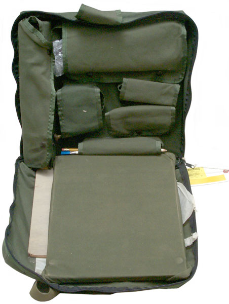
it.  When it was delivered I was surprised to see it was virtually unused.  It was lacking a compass, hand level and a few smaller expendable items like pencils and erasers, but the plane table, tripod and case were in almost new condition.

This acquisition sparked my interest - just how was this Sketch Set supposed to be used?  Why did the Army adopt it, and what was it used for?  Surprisingly, I already had the answer but didn't realize it.  Part of my collection is a library of old Army map reading and land navigation manuals that go back as far as 1917.  Prior to 1938, before the Army had established standardized topographic map production and distribution (through the Army Map Service), it was the individual unit's responsibility to acquire or create local maps for internal use.  Army doctrine, as outlined in these pre-1938 manuals, heavily emphasized military sketching.  If you were a battalion or regimental commander and you were going to the field you would ring up your engineers or S2 section and have them prepare a route sketch and a field sketch of the area you were going to be operating in.  What did the Engineers or Intel Section use to prepare these sketches?  Yup, the M1913 Sketch Set.

In 1938 it appears that the Army realized it needed to separate the practice of field sketching from map reading and land navigation.  Military field sketching was a specialized skill that required a lot of training and practice, but map reading and land navigation was something EVERY soldier would need to learn.  This is when the the famous FM 21-26 (Map Reading and Land Navigation) series of manuals got its start.  In 1938 the Army published FM 21-35, Sketching,  This FM was already in my collection, but I never paid much attention to it (I think I picked it up as part of a package purchase along with several other manuals).  A few months ago I was flipping through the FM and was surprised to see that a lot of the illustrations were of the M1913 Sketch Set!  I sat down and read the manual cover to cover and realized that it's this FM that specifically describes the use of the M1913 sketch set.  In fact, the manual is built around the sketch set and its use.

As far as I cant tell, FM 21-35 is the only manual the Army ever produced that is focused on military sketching, and as far as I can tell, the Army never updated this FM - the 1938 publication is the first and only dedicated Army treatise on the subject.  Sketching continued to be lightly discussed in future editions of FM 21-26, but never to the detail covered in FM 21-35.  Copies of FM 21-35 come up occasionally on eBay, if you'd like to get a copy.  

So, what looks like happened is that the Army kept the M1913 sketch set in the inventory (and continued to manufacture them up through at least the mid-1900s), but never updated the basic manual.  Without the manual the practice of military sketching became a lost art."

ID Info

NSN: 6675-00-641-3632
Noun: Sketching Set, Survey
"A collection of surveying equipment such as sketching board, clinometer, boxwood alidade and the like. Permits sketching approximate contours but is not intended for accurate surveys as no precise surveying equipment is included."

Case
MIL-C-3779
MFR  84583

Manual

FM 21-35 Sketching 1938.  Only published one time and not updated or republished although the M1913 sketch set was made up into the 1980s.  But without the manual to go with them, not much practical use.

Hand Receipt

The Front Cover
Reference:
Department of the Army        SC 6675-90-CL-N03-HR
Supply Catalog:                    SC 6675-90-CL-NO3
Dated:                                   July 1986

Department of the Army Supply Catalog
Hand Receipt Catalog
Covering Content of
Sets, Kits, and Outfits Components List

Sketching Set, Surveying:
Military Field Sketching
(NSN 6675-00-641-3632)
(LIN T63238)

This SC/HR supersedes SC 6675-90-CL-NO3-HR manual dated October 1982
Headquarters, Department of the Army
July 1986

December 1986

End Items Table


NSN
Fig
Description
6675-00-641-3632
-
Sketching set, Surveying: military field sketching
6675-00-382-8571
1
Alidade, Triangular: Boxwood; 8 1/2 in. Lg, 90379 Alidade
6675-00-334-5174 2
Case, Engineer Battalion Drafting equipment: DCanvas, 16 in inside W, 17 in Lg, 4 in depth; 2 handles for carrying sketching equipment
6675-01-196-6971 3
Compass, Magnetic, Unmounted: Lensatic, induction damped tritium activated luminous material
(Note: Item is a radioactive commodity and will be handled in accordance with TB 43-0141)
6680-00-641-3206 4
Counter, Reciprocating, Hand Held: 4 fig in register; reset device, finger ring holding device Type I, Class 2, CG-C-620 (81348)
This is a hand held Veeder Root type counter.
6675-00-355-5421 5
Cover, Sketching Board: Waterproof; Black cotton duck; 27-1/2 Lg 17.020 W
7510-00-619-7714
Eraser, Rubber: Cylindrical; wood cased; 6 in Lg, 3/16 in dia; 12 per pkg
7510-00-223-7046
Eraser, Rubber: Pencil rectangular; beveled ends; 2 3/4" lg; 7/8 in wd, 1/4 in thk (81348) ZZ-E-661, type I, grade B, style A
6675-00-641-3163 6
Level, Surveying: Abney; sq cross sect, 7 in lg; nonmagnifying sighting device; mtd vertically, graduated to 60 deg on side, 150 pct grade and 100 units topgraphic other side; w/case (81348) GG-L-260
7530-00-285-3084
7
Paper, Tracing: 13-1/4 x 12-1/2 in, 72 sheets per pad; white; translucent; 100 pct chemical woodpulp; fuller board envelope w/string tie and 2 buttons, Type II, UUP00561 (81348) (AMDF-PD)
7530-00-272-9820 8
Pencil, Lead, Graphite: General purpose 3H; 5 in Lg; 75364 (2200)
7530-00-222-1250
Pencil, Mechanical: Clutch action; 0.070 to 0.076 in dia lead accomodated; for artists and drafting leads; 75364 1511
9330-00-4675

Plastic Sheet: Clear plastic; 13 1/8 in Lg; 12 1/2 in wd; 0.010 in thk (81348) L-P-535, type II, grade GU, composition A
6675-00-266-6880
9
Protractor, Rectangular: Plastic; 6 in lg; 1 3/4 in wd, 1/8 in thk; 1 deg graduations; 1 to 20,000 and 1 to 62,500 yd scales, 100 yd smallest increment, 1 to 20,000 meter scale, 100 meter smallest increment; 1 in scale 1/10 in smallest increment; (81349) MIL-P-11720
6675-00-371-9458
10
Sketching Board: 15 in Lg, 12-1/2 in W; 4 screw paper clamps; w/built-in compass; w/graduations on one edge; reference scales on margin; 3/8 in- 16 thd size binding screw for tripos mtg: (81349) MIL-S-3720
7510-00-272-6887

Thumbtack: 1/2 in head dia; 5/16 in pin lg, steel, 100 per box, Type II, Class 1, FF-T-311 (81384)
6675-00-378-8470
11
Tripod, Sketching Board: Wood; folding; 40-3/4 in w/brass screw; 15 in leg Lg; (81349)

Set Layout

M1913 Sketch Set, Surveying, Military Field
        Sketching
Pocket
Qty
Description
0

Table Top in Canvas Case
0

Clear Plastic Sheets
0

Tracing Paper
0

Triangular Scale
1
3
Tripod Legs
2
1
Tripod Head
3
1
Clinometer Leather Case
3
1
Clinometer
4
?
? (empty)
5
1
TI-1766III Light Powered Calculator
6
1
Felsenthal Instrument Co. Part No. FAE-9A - combined 6 inch ruler and protractor.
7
2
Pencils
7
2
Pencil sized erasers with brushes on end

Misc

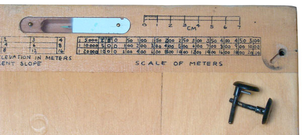
By removing the plastic cover on the broad's built-in compass and cleaning it with Optic Guard Anti-Fog Optical Cleaner the electrostatic charge seems to have been removed.  Prior to applying the cleaner the compass needle was attracted to the plastic and was stuck.

Related Web Pages

Surveying - patents -
K&E 76000 Alidade
Alidades -
Leitz 115A Transit
T. F. Randolph Level & Tripod
K & E hand level & other hand levels
Stadia

Links

Google Books search for "Plane Table" with Full View = on
The plane table and its use in surveying  By William H. Lovell, 49 pages
The plane-table and its use in topographical surveying by Alexander Medina Harrison, 79 pages
The plane-table and its use in topographical surveying by U. S. Coast and Geodetic Survey, 92 pages


Back to Brooke's PRC68, Alphabetical Index, Products for Sale, Navigation Orientation & Position, Alidade, Sundials, Surveying, Time & FrequencyMilitary Information, Home

[an error occurred while processing this directive] page created 21 Jan 2010.