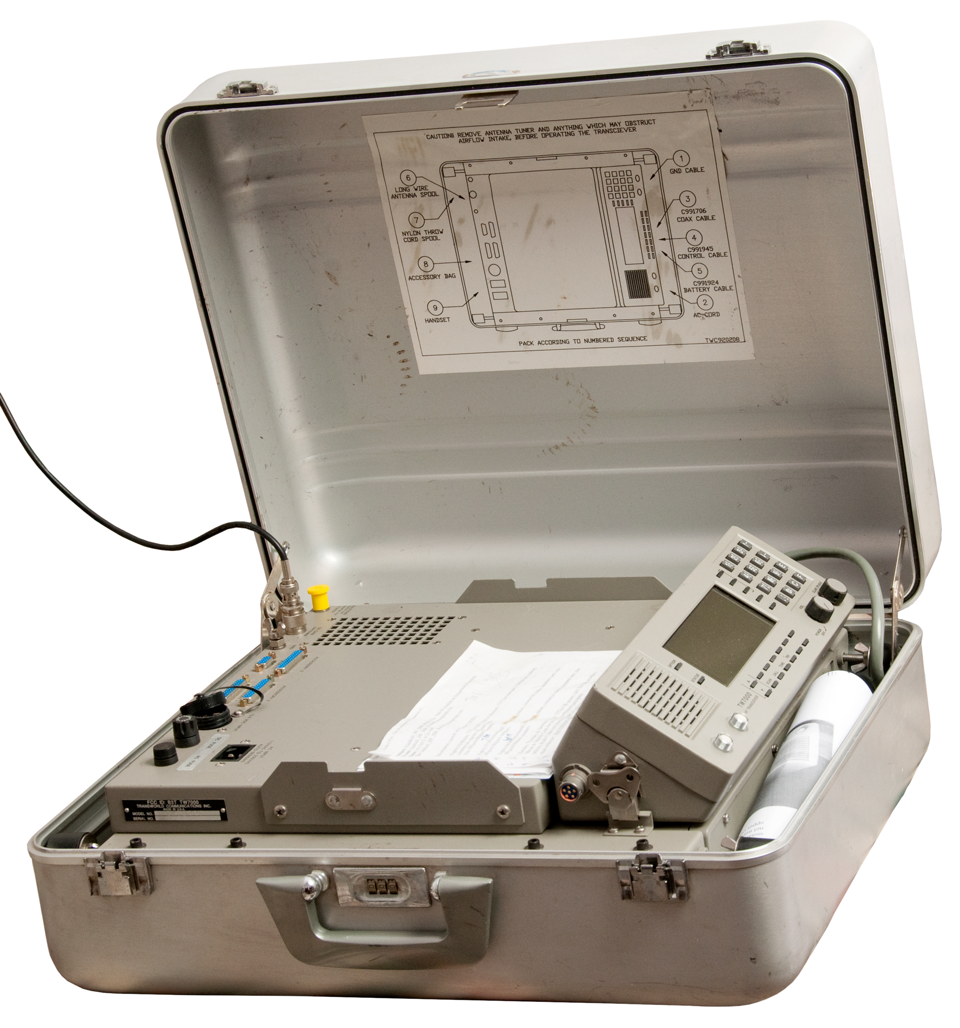
Transworld TW7000F HF SSB Flyaway Transceiver
© Brooke Clarke 2015 - 2022Fig 10
As part of my interest in amateur radio (N6GCE) and suitcase or flyaway HF radios in particular Flyaway HF radios. See Related below.
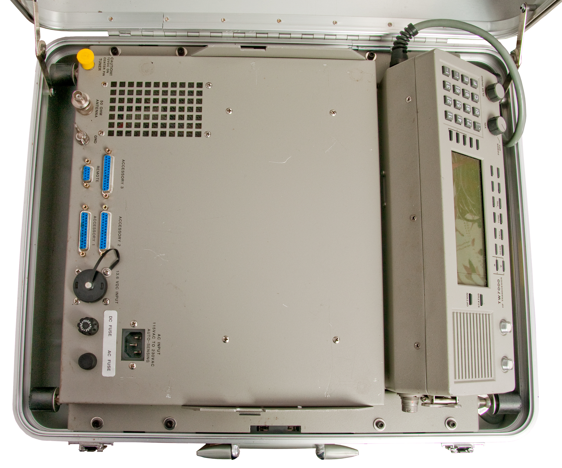
"The Transworld TW7000F is an advanced 100-watt "Fly-Away" HF transceiver package providing voice and data communications over the 1.6 to 30-MHz range from one compact package, meeting IATA requirements for underseat transport aboard aircraft. The TW7000F comes complete with a deployable automatic antenna tuner, wire antennas, microphone, and all accessories required for normal operation.
The TW7000F includes the following equipment:
In addition, the control panel at the transceiver can easily be removed from the package and remoted for operational convenience. the TW7000F also has two output RF connectors: a BNC used to connect to the accompanying antenna tuner, and a SO-239 for connection to broadband antennas."
- TW7000 advanced HF transceiver, covering 1.6 - 30 MHz spectrum in 10-Hz steps.
- Internal 110/220 Vac switchmode power supply with automatic changeover (or 12 VDC).
- Automatic antenna tuner, deployable up to 25 feet using a single coaxial cable.
Supported modes: USB, LSB, CW, PCS & AME
RF output power levels: 10, 25 or 125 Watts.
(from Operator's manual p/n: TW7000F-MSOP)
Options
Showing a list of all mentioned in the Operator's manual.
Main of these are options on the main CPU board and may consist of different or optional ICs and/or jumpers.
Installed/n.a.
7000WB
Wide-band Data Filter
7000TC
Selcall/Transcall/TransAdapt
7000CLK
Time of Day Clock
7000RS
Computer Control
7000ALE
FED-STD-1045 ALE
7000NB
Noise Blanker
7000HS
High 0.1 ppm Stability Ref Osc
7000FM
VHF/FM module
Connectors
There are two Hirose connectors on the front panel for factory microphones.
To connect some other microphone you need the following mating connector:
Mouser Part #: 798-SR3010PM6P71
Hirose p/n: SR30-10PM-6P(71)
Description: Standard Circular Connector 6P Male Straight Solder Plug Cable Connector Screw Lock
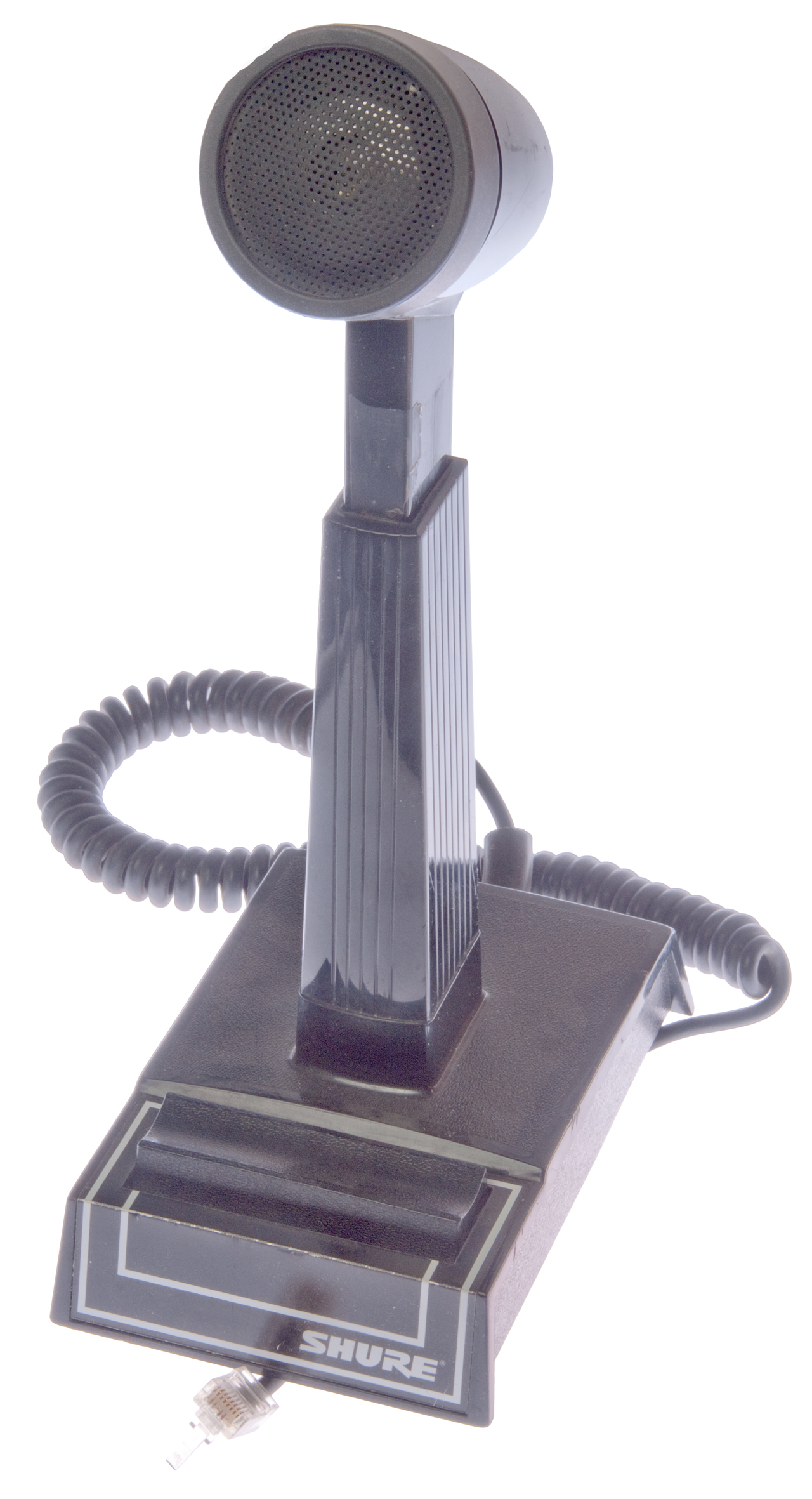
Desk mics: Shure 444D or Shure 550TSB/II, Hand Mikes: Shure 527B
Shure 444D Desk Microphone
Note: Modular plug
Note: DC blocking cap, Normal/VOX switch, Hi/Lo Z switch
Accessories Supported
This is done by having the appropriate signals available on the interface connectors.
- Existing TW 6 section filter and new TW 7 section filter RF power amplifiers.
- TWRTU200, TWRTU250, TW5100, TW9000, 600 Ohm voice encryption, or similar type in-line audio accessories.
- IBM style keyboard for ALE messages.
- Transcall/Selcall ALE Alarm
- Retransmit Output
- External Speaker
Modules
There's a discrepancy relating to the Jack numbers assigned to the modules in the manual and the hardware.
Manual
Jack
Hardware
NB/FM
J2
NB/FM
Not Installed
Ref/Ctrl
J3
High Stability
Dwg 738322 Rev ESynth
J4
Synth
001-00901
wo: 32334
Rev B Seq 43
5 MHz IF
J5
5 MHz IF
TWC 738208 Rev D
w/ XF2 300-3050 Hz Filter
75 MHz IF
J6
75 MHz IF
WO-32843
001-00710
Rev A Seq 56
Audio
J7
Audio
DWC 738211 Rev F
J8
Option 1
J9
Voice Enhancement
VEM-101
assy p/n: 5931-101000
Option 2 J10
Empty Option Slot
Remote Control
Extended Control
J11
Empty RCU/ECU slot
J12
ALE
J13
ALE
TWC 738229 Fev A
Main Processor
J14
Main Processor
TWC 738210 Rev g
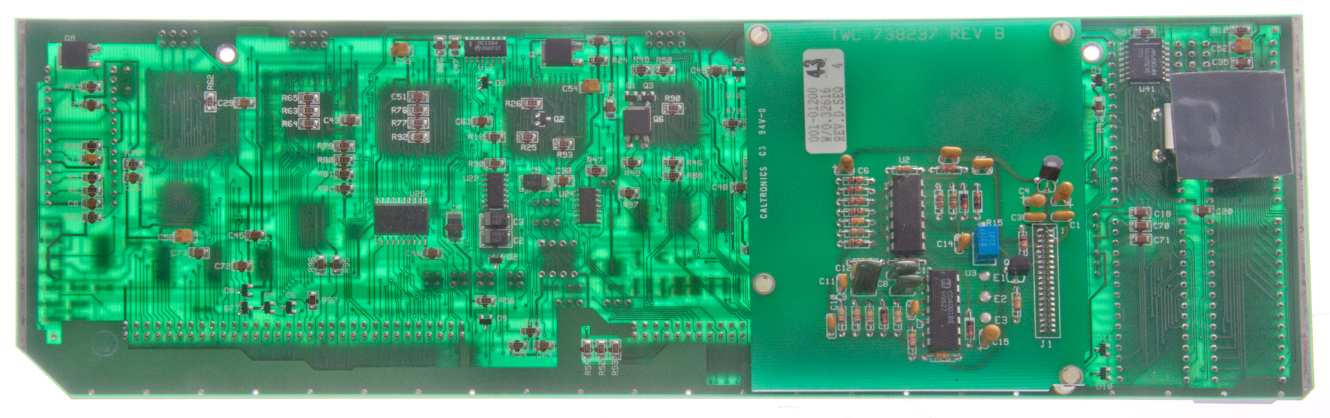
&
Squelch 738237 Rev B
J15
VSWR
J19
VSWR
RF Filter
J22
RF Filter
Main CPU Board
This is the heart of the radio. Most of the options are set either by what ICs are installed and/or how the jumpers are installed.
U1 is the Motorola 68HC000 (Wiki, series) micro processor (not a micro controller) which is similar to what was used for the first Apple MacIntosh portable (Wiki). Other ICs with 68nnn type part numbers are related.
Socketed IC Table
IC
Pins
p/n
Label
Function
Optional IC
U1
20
GAL16V8B, 25LP, H419D08
-
PLD (Wiki)
U2
32
ROM
701AD, U2, BB1B
U3
32
ROM
702AD, U3, 731
U4
28
S32
Dallas, DS1644-150
Timekeeping RAM
9731B2H
096029
-
Clock/Calendar
U5
28
S32
MS62256CLL-70PC
-
32kx8bit Static Ram
U9
8
na
-
Data Interface
SN75176
U10
28
na
-
Modem
MSM6946RS Modem
U18
44
na -
ISDN rem
FSK rem
MC68681FN DURAT
MC68681FN DURAT
U19
44
SCN68681C1A44
-
ALE
SC/TC/TA
MC68681FN DURAT
MC68681FN DURAT
Jumpers
Jumper
Function
Pos 1
Pos 2
Pos 3
Pos 4
JU1
CPU Clk
AB: Clk2
BC: Clk1
-
-
JU2
Mem type
AB: EPROM
BC: Flash (U42)
-
-
JU3
U2 Pins
AB: 28
BC: 32
-
-
JU4
U4 size
AB: 32k
1000 Chan
BC: 8k
-
-
JU5
Back Up Batt
In: Batt
out: Test Bat
-
-
JU6
J15 Data Interface
AB: RS-232 BC: RS-485 -
-
JU7
J15 Data Interface AB:RS-232
BC: RS-485 -
-
JU8
J15 Data Interface AB: RS-232 BC: RS-485 -
-
JU9
J15 Data Interface AB: RS-232 BC: RS-485 -
-
JU10
No. of Channels
A:1000 Chan
B:-
C:-
D:RAM Clear
JU11
U17 ADC Int
A: ISDN rem
A: FSK rem
B:ALE
B: SC/TC/TA
-
-
JU12
A: B: ISDN rem
B: FSK rem
C: D: JU13
A:ALE
A: SC/TC/TAB:SC/TC/TA C:- D:- JU14
J14 Opt A: B: -
-
JU15
J14 Opt A:- B:- -
-
JU161
J14 Opt A: Encr
B: Encr
-
-
JU17
J14 Ser1
A: B: -
-
JU18
Data Pol
In: ?
out: ?
-
-
JU19
In: ? out: ? -
-
JU20
Clock
AB: N0
BC: Yes
-
-
Note 1: Alpha 27 (Voice Encryption) showed "option not installed" and J16 had no jumpers, so I moved a couple of jumpers that were not doing anything to A & B.
But Alpha 27 still shows "option not installed" How to configure the VEM? Ans: I don't have voice encryption, but do have the DSP Voice Enhancement Module )VEM).
The VEM is a Voice Enhancement Module so I need to remove those jumpers from JU16.
Pressing <Alpha> 2, 7, <E> brings up the Voice Enhancement Module and the option for Type 1 or Type 2 operation.
During startup Option 1 Module and Clock appear.
Note, as shown in Fig 2 below, the options are shown at the left of the LCD. In my case there are only OPT and ALE.
When you press OPTION each blinks in turn to indicate that's the active option. When OPT is blinking the Optional slot 1 Voice Enhancement Module is the focus and when STATUS is pressed it toggles ON and OFF that option. When listening to a station I can hear an improvement in the signal/noise ration when it's on.
AC Power Supply
Mean Well RSP32012 (Jameco): Output: 12 VDC @ 26.7 Amps
Photos
TW7000FA
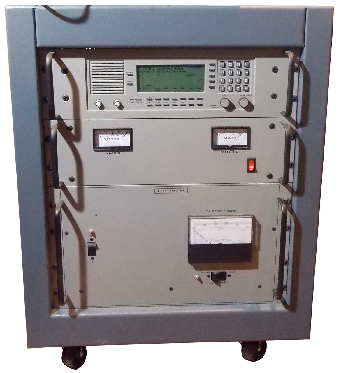
Fig 1 Front Panel in Rx mode
Fig 2 Close Up of Front Panel in Rx mode
Fig 3 Close up of Front Panel when PTT is pressed
Fig 4 Top View
Mounting bolts are either:
4mm hex head with 5-0.8 thread x 15mm
or
3/32" hex head with 10-32 thread x 5/8"
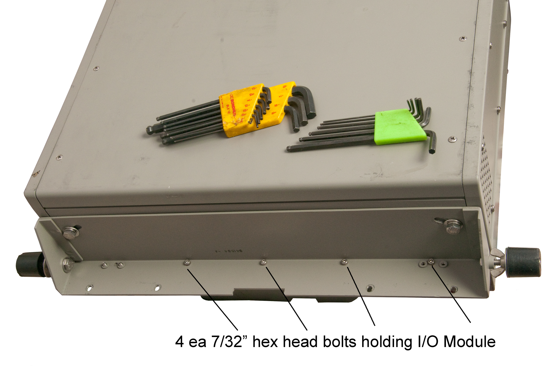
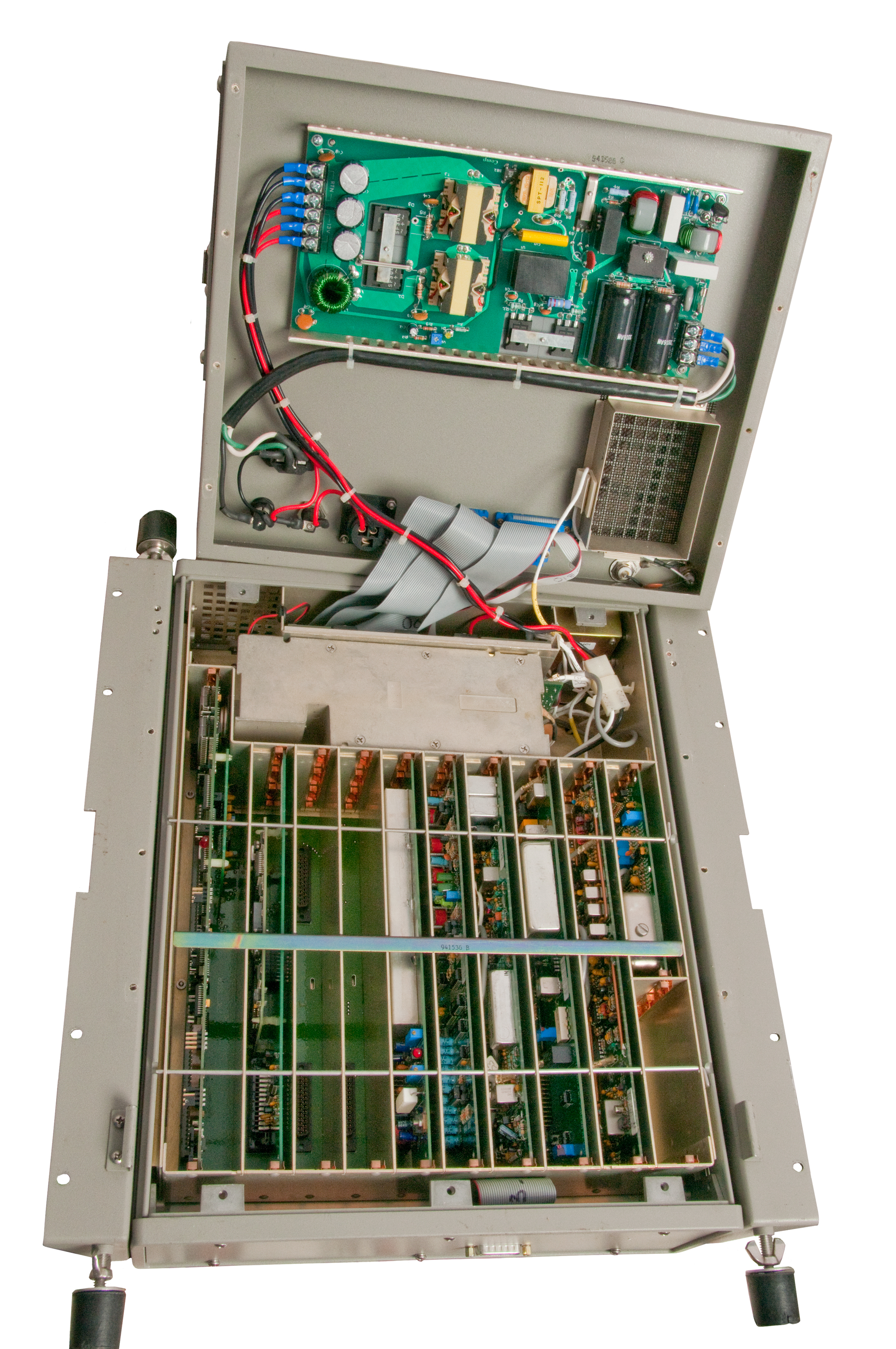
Do NOT remove any screws in the I/O module. They are holding components on the other side. See Fig 8 & 9.
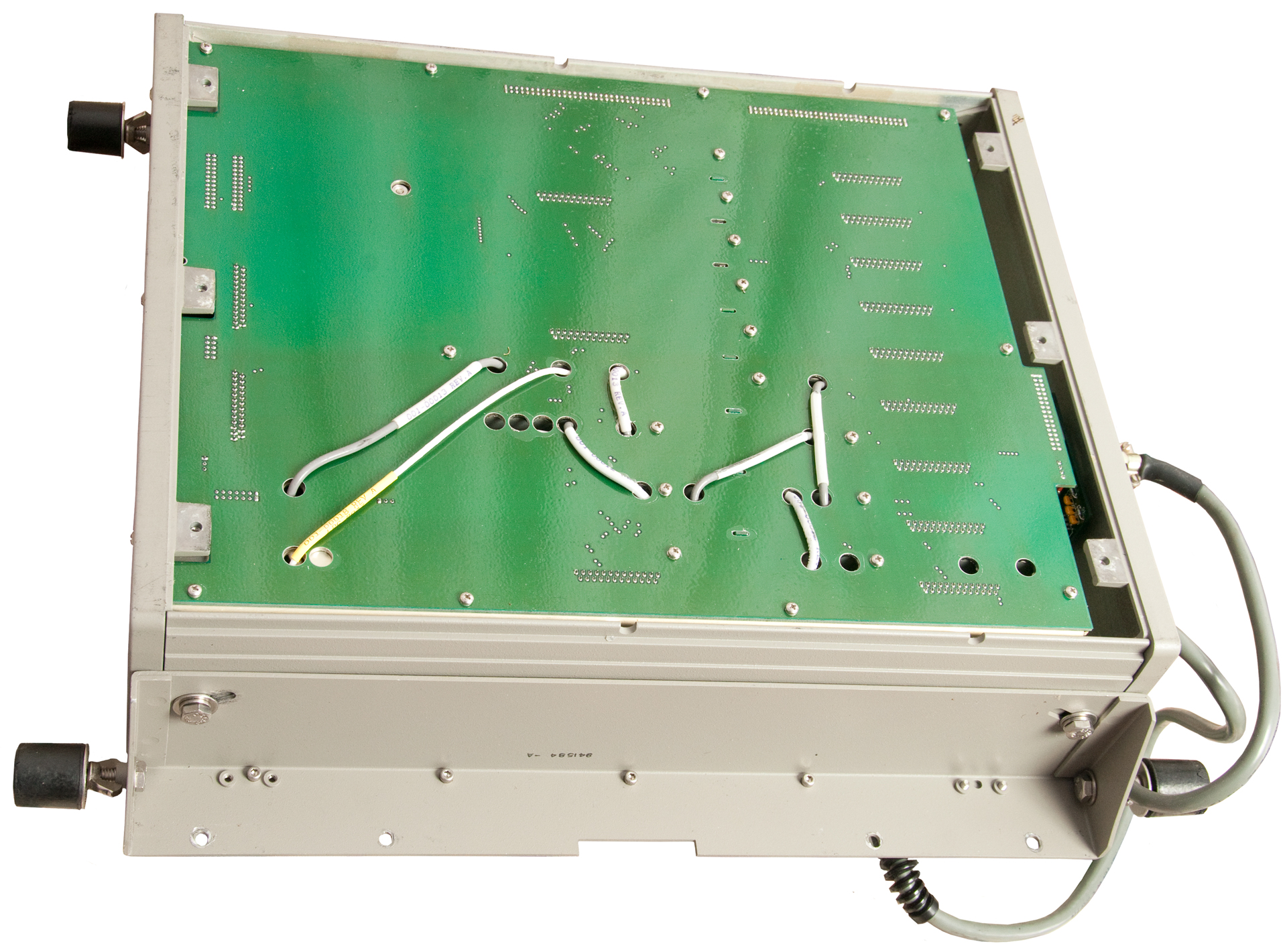
Fig 5 Bottom inside after removing 6 (+) screws.
This is the back of the mother board.
Fig 6 Rear Inside after removing (+) screws.
This is the back of the internal 13V input to various DC voltages power supply. The 3-lead regulator ICs are at the top of the board and flat against it behind the I/O ribbon cables.
The small IC is an MC3416 voltage regulator.
Fig 7 7/32" hex wrench Bolts holding I/O Module
4 ea this side and 4 ea on opposite side
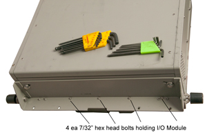
Fig 8 Bottom side of I/O Module with
120/240 VAC to 13.9 VDC power supply
Connector on front is for the front panel.

Fig 9 Inside main chassis
Metal box in back of main chassis is DC power supply
and RF amp. I expect that's where the problem is.
Note "L" bar p/n 941536 B is just pressed in place.
Trapped by cover. Notches down.
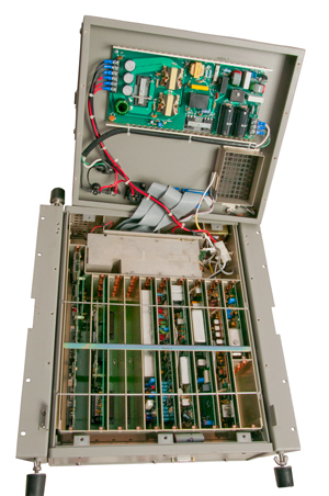
Fig 10
Fig 11 RF Power Amplifier
J10: TX RF Low (upper left below)
J12: TX RF Hi (near bib binocular core, right below)
Fig 12 Output RF Filter
J50: Antenna
J51: From PA
J52: RX RF
Fig 13 J14 & J15 Main CPU board top
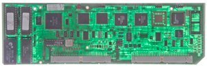
Fig 14 J14 & J15 Main CPU board bottom
w/ Squelch TWC 738237 Rev B
Fig 15 J3 High Stability Reference/Control
Fig 16 J4 Synthesizer
Fig 17 5J5 MHz IF with both filters
Fig 18 J6 75 MHz IF
Fig 19 J7 & J8 Audio
Fig 20 J9 (Option 1) Voice Enhancement (DSP Noise Blanker)
Fig 21 J13 ALE
Fig 22 DC to DC Converter
TW7000 500 Watts
System from U.S. embassy in Africa and saw service at a Voice of America transmitting plant on Sao Tome Island. Photo taken by Charles Lewis, KY4P
TW700
Power Supply
500 Watt Amplifier
Prior to bidding on this radio asked the seller in another country to confirm that it was fully functional because none of the eBay photographs showed a powered up front panel. I was assured that the radio was fully functional, but when it arrived the front panel turns off when PTT is pressed. That's to say the transmit function it totally missing.
The voltage on the DC input connector (13.9 V) does not change between Rx and Tx modes. So maybe something is wrong with the DTW power supply, not the AC supply.
Troubleshooting Data
LCD turning off when PTT pressed.
The autoswitching AC power supply has one output at a nominal 12 Volts DC, which measures 13.9 VDC. The transceiver is powered by this voltage.
Current consumption is aproximatley:
Receive
10 Watts out: <4 Amps
25 Watts out: <10 Amps
125 Watts out: <22 Amps
1 March 2015 - The main problem of the LCD blanking was caused by a handset that was not an H-250.
I found my U-229 breakout box and checked the TW7000F.
When grounding pin-E to Pin-A the LCD switches from Rx to Tx and there's a tone from the speaker.
Also when grounding pin-C to Pin-A the LCD switches from Rx to Tx..
I think the handset I was using is some type of special and not an H-250!
But I still have the none or bad synth message so will need to open it up and check the reference frequency cable at both ends.
Broken Suitcase Latches
Both latches have come apart. Not sure why. Maybe they are not rated to for the weight of the loaded suitcase?
Looking or replacements that are strong. Let me know.
Fig 35 Zero Halliburton case (support email)
Fig 34 Holes: 3/16 or 5mm diameter
Left - Right spacing about 19.5mm (3/4")
up0dn spacing about 29mm (1-1/8")
Fig 33c
Marked:
Franzen 1401
US patent 4679833Closure mechanism for suitcases or the like, S. Franzen Sohne Gmbh & Co., Jul 14, 1987 -
Found what looks like an exact replacement from eBay seller ekluggage Title: Replacement Luggage Zero-Halliburton Lock/Latch 1 Pair
Note pair means two latches i.e. the left and right latches.
TW7000F HF SSB Transciever Operator's Manual, p/n: TW7000F-MSOP, Pub: 991508, August 1993, Rev: A
TW7000F HF Tranceiver Technical Manual, m/n: TW7000F-MS, Pub: 991515, Dec 1994, Rev: B
Flyaway radios:
Harris RF 3200ET Fly Away H.F. Radio
TW100F/AT Transworld Datron Fly Away H.F. Radio
Other radios:
ICOM 706 Mk II G HF & VHF low band mobil transceiver
ICOM R7000 Receiver
NRD545 Receiver
page created 8 Jan 2015.


