URT-44 Over-the-Horizon COSPAS-SARSAT Personnel Locator Beacon
© Brooke Clarke 2016 - 2020Description
Photos
Related
References
Links
Background
Got this as part of my interest in survival equipment. The "Over-the-Horizon" in the name of the radio reflects the fact that it works by talking to satellites rather than the line-of-sight range that the prior UHF radios had to nearby aircraft. But the prior UHF radios were also received by the SARSAT satellites and so were also Over-the-Horizon" so this use of that term is marketing hype.
Note that the 121.5 and 243 MHz beacon transmissions are also supported by this radio so nearby pilots will also hear the transmission. The new part is the 406 MHz digital data beacon (Wiki) aimed at the SARSAT system. As far as I know modern military planes do not have "guard" receivers for the 406 MHz transmissions.
Description
There are two modes of operation.
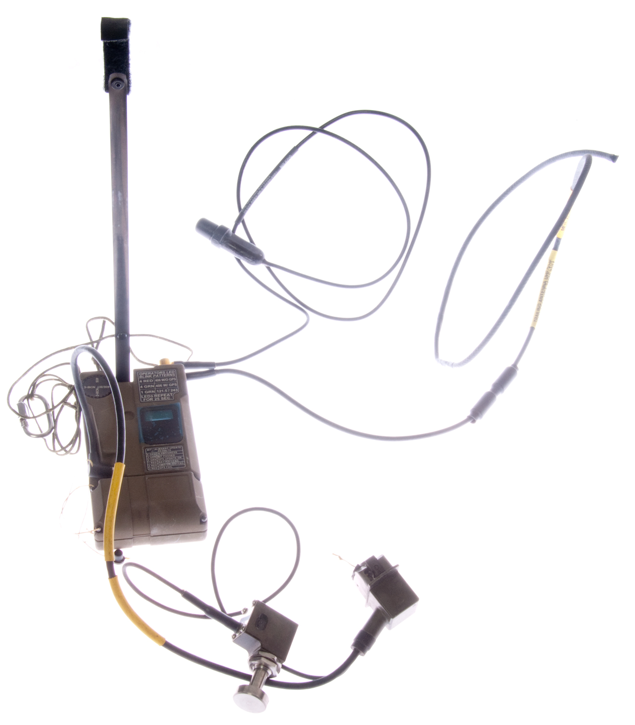
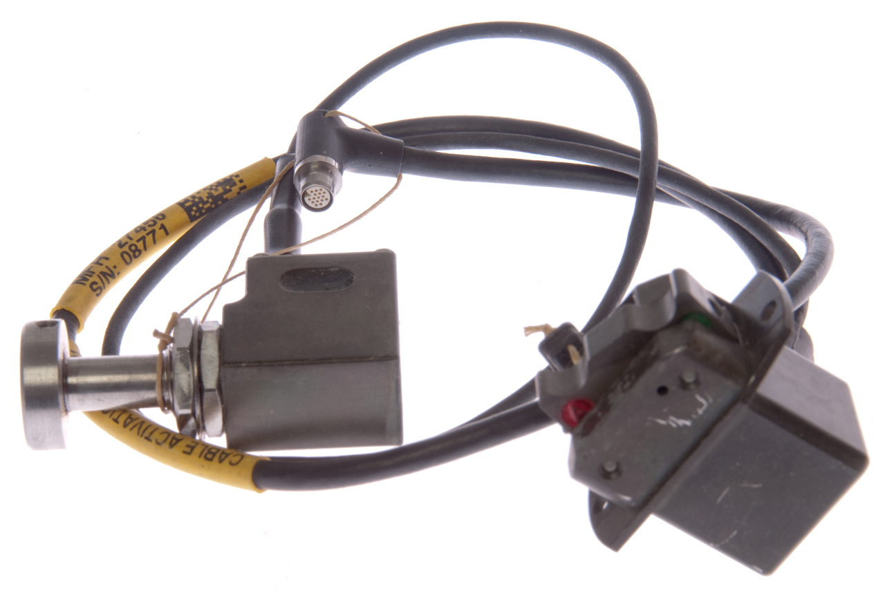
Emergency Locator Transmitter ELT with the accessories shown in Fig 1 below when installed with an ejection seat (Wiki, ACES II). The radio is installed in the survival butt pack and stays with the aircrew member. The seat ends somewhere else so not part of the ejection seat. Uses the external trailing wire antenna, the external GPS antenna and the activation cable.
Personal Locator Beacon PLB with the accessories removed and operated manually. Requires deploying the built-in tape antenna.
Was intended as a replacement for the URT-33 Survival Radio. "The Air Force discovered the beacons’ antennas, batteries and other electronic components weren’t up to the task (Time mag)".
The potential problems are:
Battery Life - should be 5 years and then have power to run the beacon transmitter. The size seems small. The PRC-90 battery is huge by comparison. Even my PRC-90 battery adapter used four CR123 batteries which is at least twice the capacity of this battery compartment.
GPS - Time To First Fix (Wiki: TTFF) is about 15 minutes. So in a bail out situation the GPS position will not be available until the pilot has landed assuming that happens in less than 15 minutes. Note each GPS satellite has almanac data for all the satellites, so once one satellite is being received it will give the receiver data on where all the other ones are. The beacon would be very much more useful if it could start transmitting the location as soon as it was activated. One way to do that would be to connect the aircraft MIL-STD -1553 (Wiki) to the beacon radio as well as aircraft power. That way the radio could be constantly getting not only the almanac data but also the ephemeris data and so would know it's position all the time. Another way to would be to just power the radio all the time so the GPS was active and only turn on the beacon transmitter when there is an ejection.
Operationally there is no need for a GPS mode where the GPS downloads the ephemeris data and fixes it's location. The BIT does not last long enough to do that. So testing the URT-44 becomes problematical.
Components
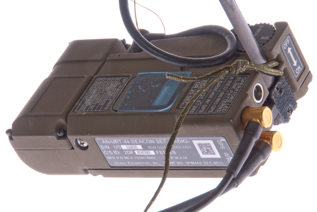
AN/URT-44 Beacon Set Radio, NSN: 5826-01-569-2421
Labels
Manual Operating Instructions
1. Remove trailing antenna. Deploy blade antenna.
2. Rotate mode selection switch to desired function.
3. Position beacon so antenna is vertical.
4. Slide On/Off switch to on position.
5. Observe LED blink patterns for operation status.
To turn off: Toggle from on to off 2-times in <5 sec. LED turn off.
------------------
BIT Test:
Perform step 1 with beacon off.
Rotate mode switch to 406 only.
Turn On/Off sw to on.
Rotate mode switch to 406/BIT position <10 sec.
Turn On/Off switch to Off.
See LED results.
The green LED blinks 6 times, pauses, blinks 6 times for some time, then there is a short transmission (freq?) the blinks 3 times (BIT passes). Then powers down.
Operators LED Blink Patterns
4 Red: 406 w/o GPS
4 Grn: 406 w/GPS
1 Grn: 121.5/243
LEDs repeat for 25 sec.
BIT/Almanac Update Results
6 Grn: In progress
3 Grn: BIT passes
2 Grn: GPS Update OK
1 Red: Battery Fail
2 Red Xmit or U/D Fail
3 Red: GPS Fail
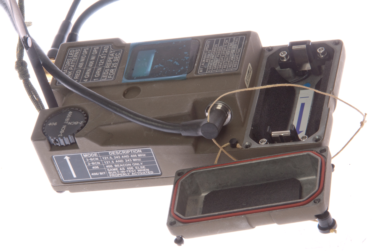
Mode Switch
3-BCN: 121.5, 243 and 406 MHz
2-BCN: 121.5 and 243 MHz
406: 406 beacon only
406/BIT: Same as 406 when Built-In-Test properly Activated
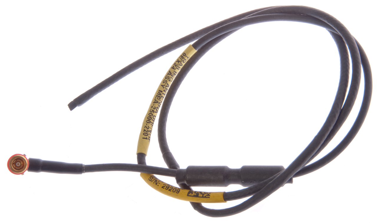
UHF/VHF Trailing Wire Antenna, MEA-25000-2201
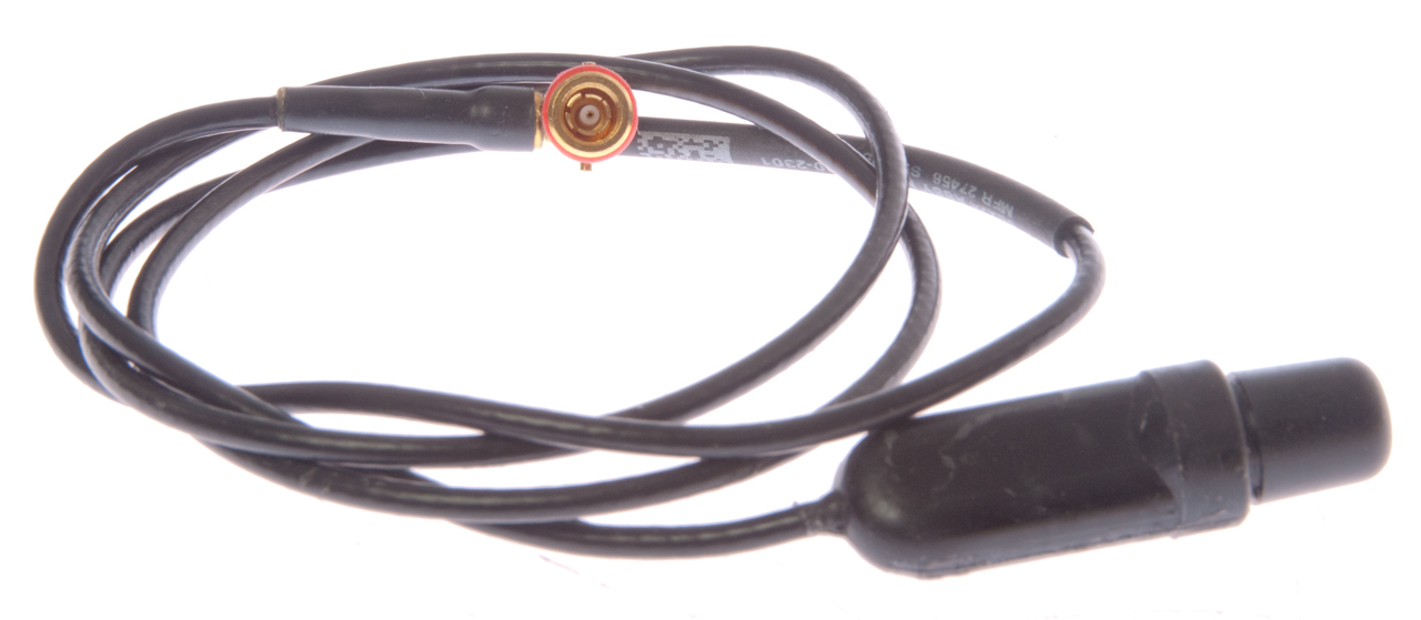
The connectors on the two external antennas both have 2 lugs, but they are positioned differently so they can only be connected to the appropriate radio socket.
GPS Trailing Antenna, MEA-25000-2301
Activation Switch Cable assembly, MEA-25000-5501
There are two assemblies on this cable.
A spring loaded push switch at the far end. I'm guessing when the plunger is out the switch turns on the radio.
A Manual (green) or Arm (red) rocker switch assembly that also contains a USB Mini-B socket. That allows programming the 406 beacon data and probably some radio self test functions.
The connector to the radio has 16 terminals and has an OD of 5.62 mm.
When the radio is connedted to a USB port (with any combination of the Manul/Arm & Activation switches) it does not accept any DC power from the USB port. That's too bad since it might be a way to solve some of the problems.
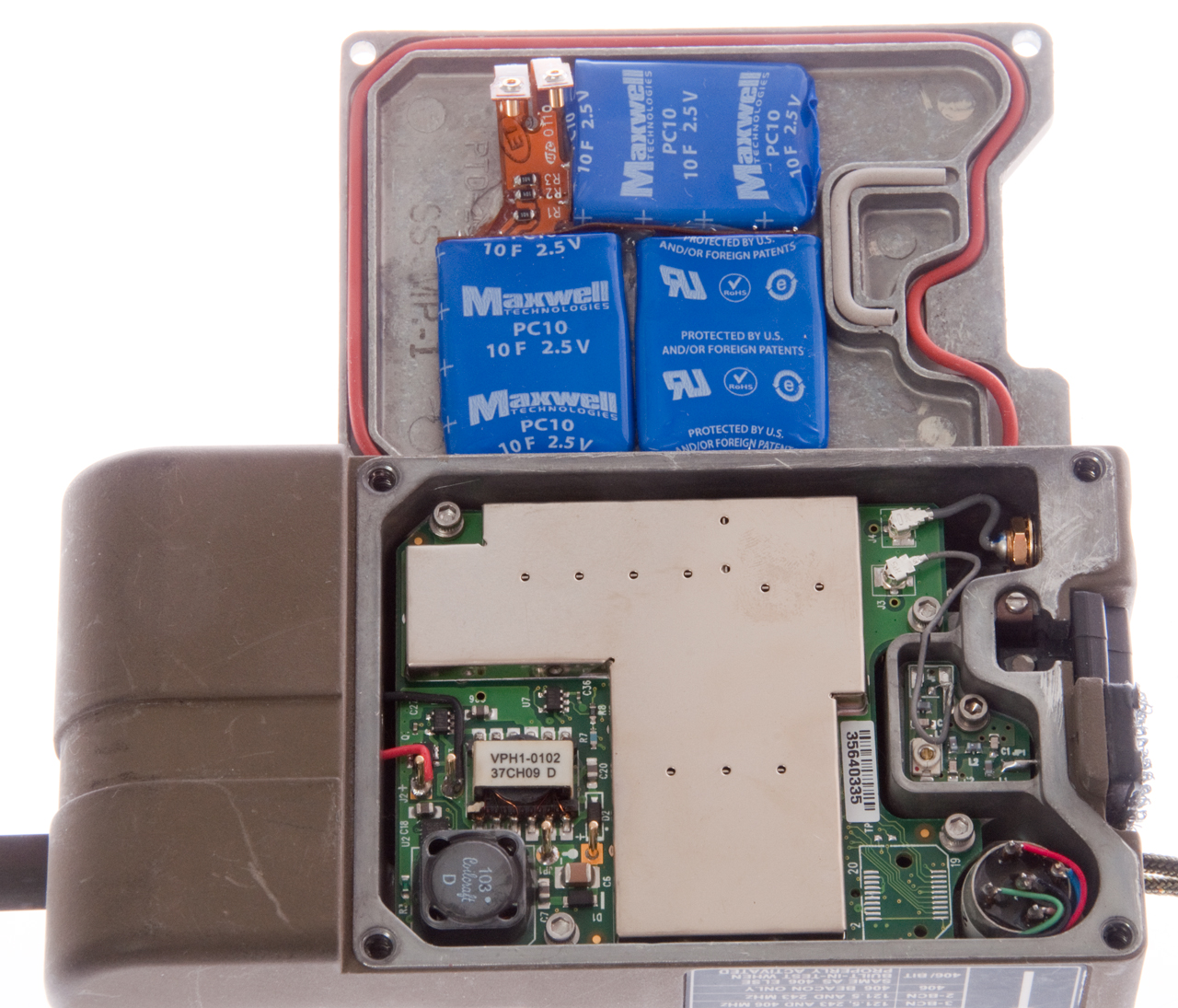
Battery
If you have one dead or alive please let me know.
NSN: 6135-01-572-9340
Lithium 3.9 Volts
maybe: 1.94" long x < 1.041" dia.
The common "C" cell is 1.969/1.909 long x 1.031/0.980" dia
So the battery might look like a "C" cell.
2016-June-15: I have a couple of 25500 Lithium (3.7 V) batteries on order along with a dual battery charger for them.
I expect that the real battery is a primary type since a rechargeable battery would not have the needed lift, but this may be a way to power it up outside.
The TF 25500 3.7 Li-ion battery does not fit even though both ends are flat. The O.A. length is 51.45mm while the distance beetween the black plastic parts is 50mm.
Battery adapters that use AAA cells are about the right size. The 4 AAA "C" size adapter fits correctly, BUT is 1.5 Volts since it's a way to use 4 AAA batteries in a "C" package.
On order is a 3 SERIES AAA adapter that should work.
Photos
Related
Survival Equipment
PRC-90 Survival Radio
PRC-112 Survival Radio
URC-68 Survival Radio
ACR/RT-10 Survival Radio
SDU-5/E Distress Strobe Marker Light
SDU-30 Distress Marker Light
References
Links
PRC68, Alphanumeric Index of Web pages, Contact, Products for Sale
Page created 2016-June-15