 |
 |
 |
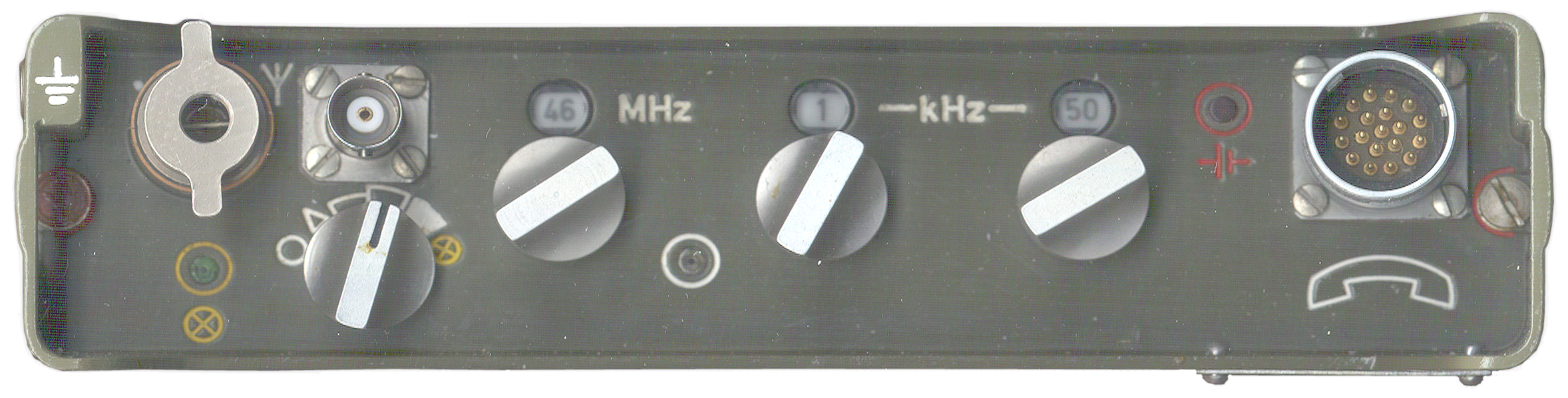
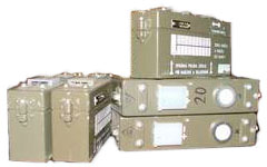
| RF-10 Approximately Full
Size |
 |
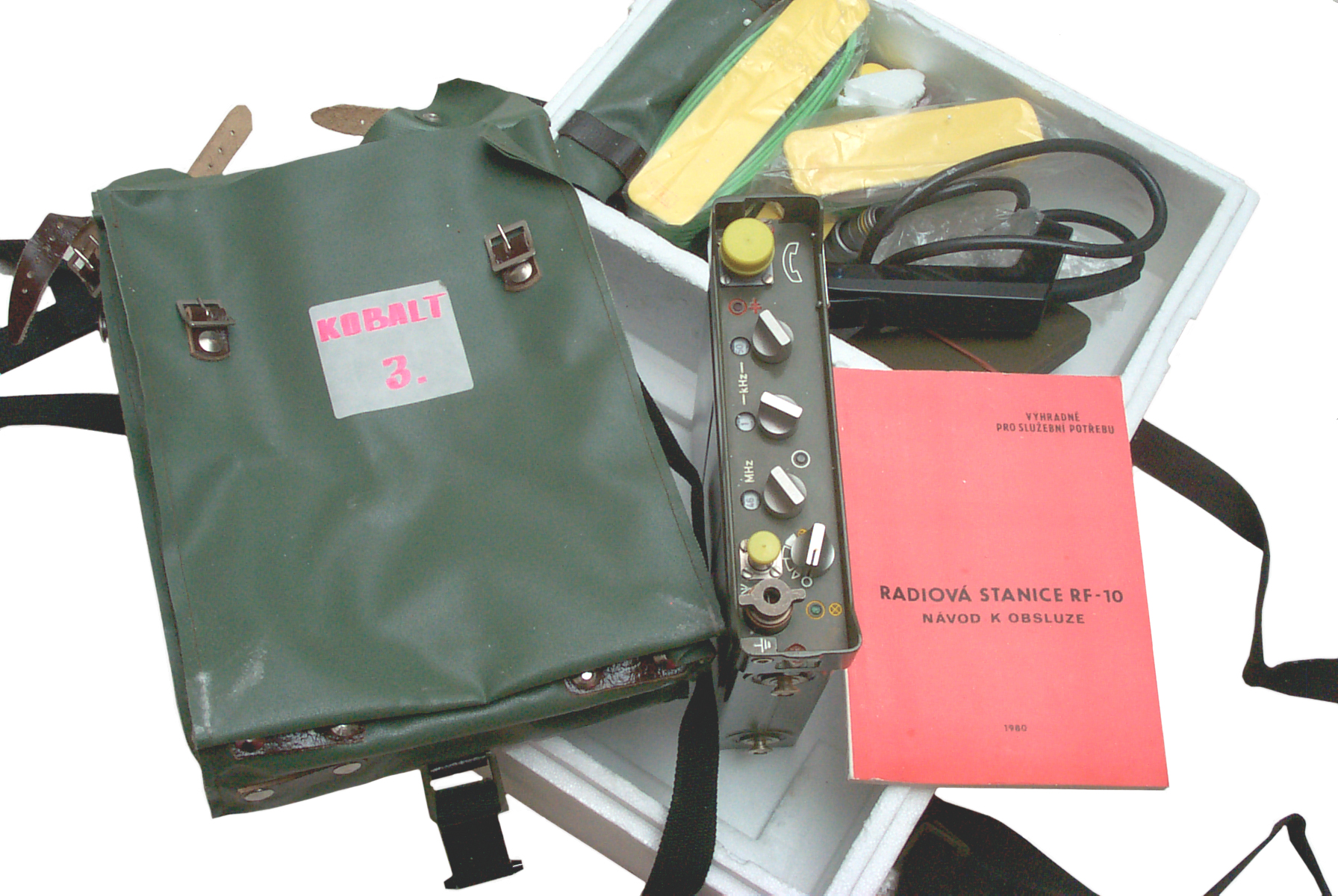
The MHz selector is allowing to set frequency in 1MHz step in between 44-53MHz.
The kHz selectors has two knobs:
left is for setting frequency in 100kHz steps in between 000-900kHz.
right is for setting frequency in 25kHz steps 25/50/75kHz.
So ending frequency in range is 53.975MHz.

Regarding the lights on the top panel:
Left green light with yellow ring is indicating the transmission > in test mode (mode switch to test mode same icon).
Middle white light with white color ring is indication all the time that PLL synthesizer is locked correctly.
Right upper side red light with red ring is indication of the discharged battery pack.
Translation of part of web page provided by Bill Howard:
I had a friend translate the Czech web site on the RF 10 radio set. Here is his translation for anyone interested in Czech radios.Bill Howard
| Mil Pack: Radio Set RF-10 Technical Description Part 1.pdf - 228 pages. Tom Simpson KM4ZOM added enhanced photos. Table of Contents at end, missing appendices. Book 1 Schematics - 19 pages. RF-10 radio Book 2 Schematics - 4 pages. KZ-10 Test Set? Book 3 Schematics - Accessories Boxes &Etc. - 8 pages. |
 |
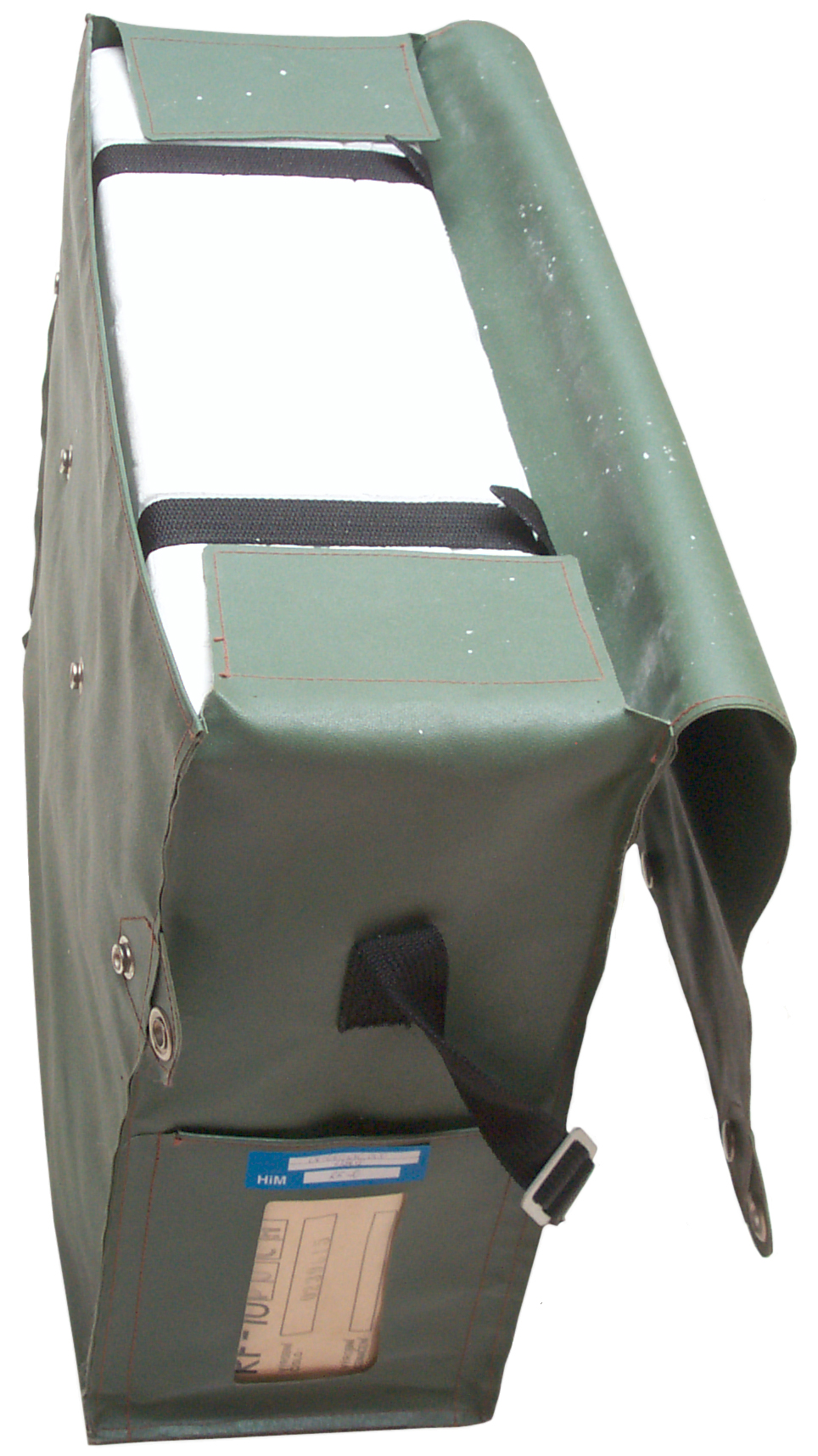 |
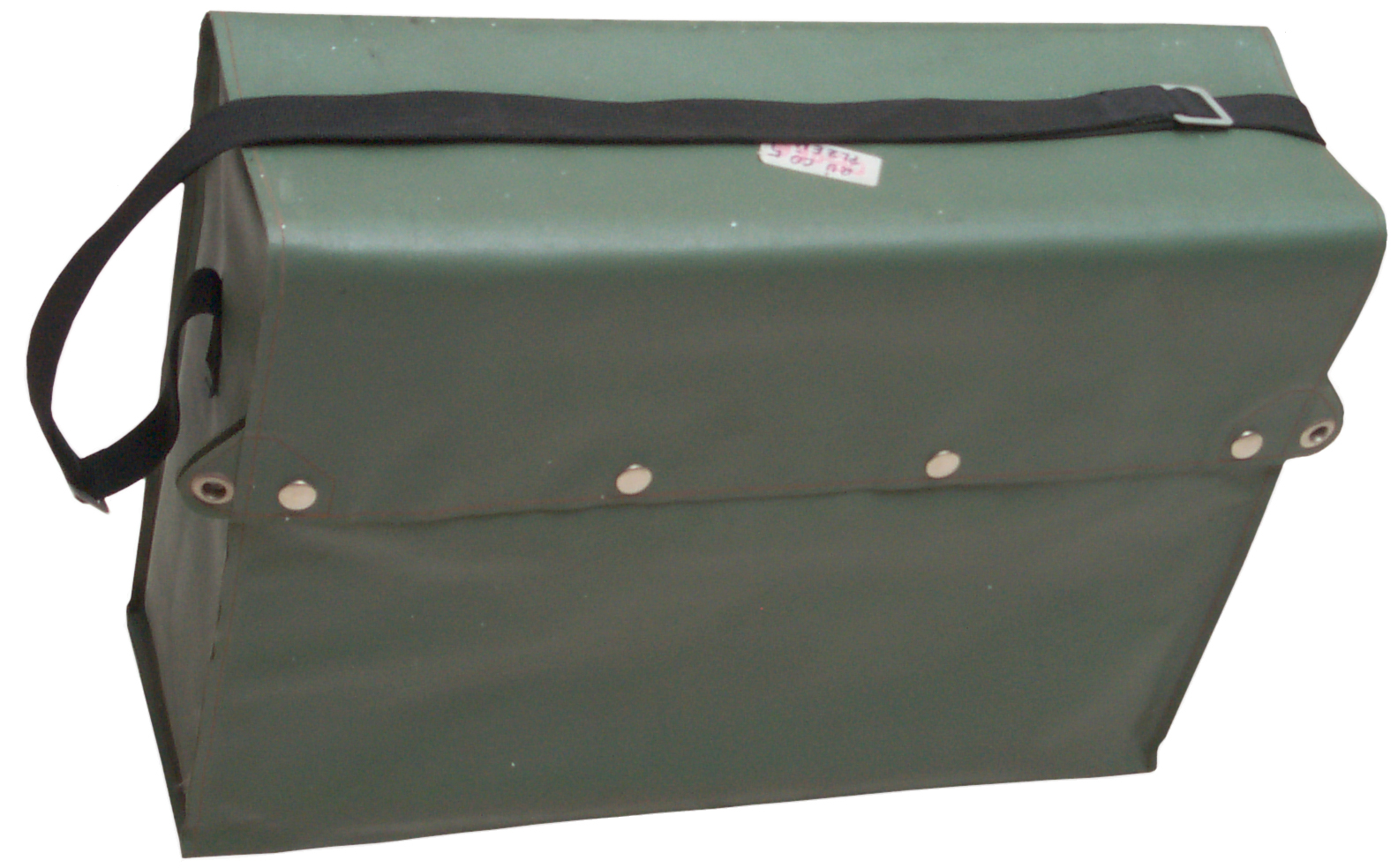
| System
Bag Front |
System
Bag End |
 |
 |
| Styrofoam
Open Antennas in lid Radio & Accessories in base |
Radio
bag, Radio & Manual |
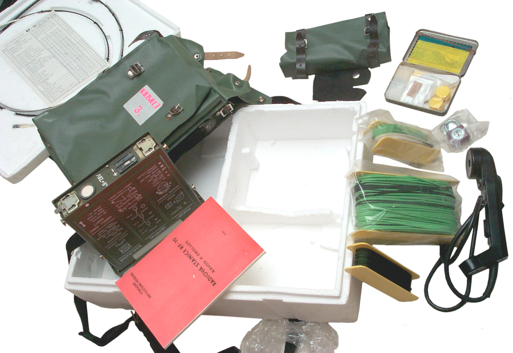 |
Pouch (battery or battery
box?) Wide strap for radio bag. Metal box with universal tool and misc. small parts. Padlock. 3 each - Wire on spool handset The accessory pocket has a bunch of stuff. Need to do inventory Pouch at top of photo probably is for battery box which is missing. |
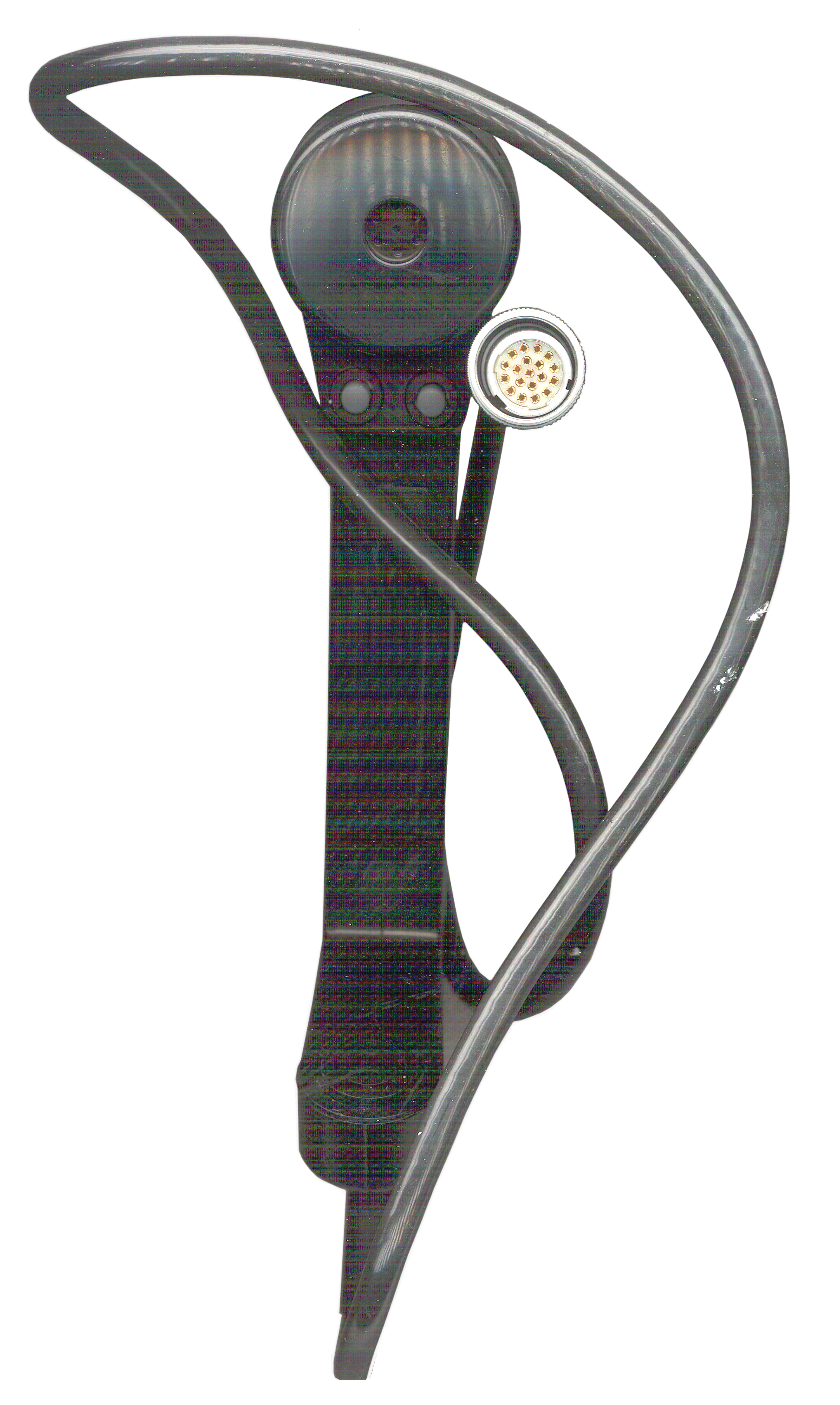 |
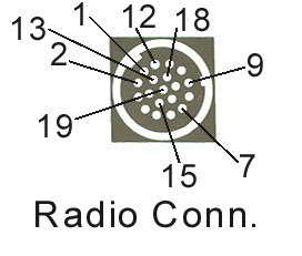
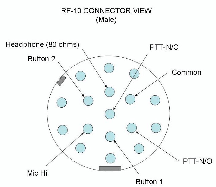
The Handset has in addition
to the normal Push To Talk switch two additional pushbutton switches. The Connector has 19 female contacts and no marking on the face or anywhere else. The Microphone is of the noise canceling type so your lips need to be touching the front of the mike when using. There are two screws at the top and bottom that would allow opening the handset for repairs. It's not a throwaway like the H-250. |
 |
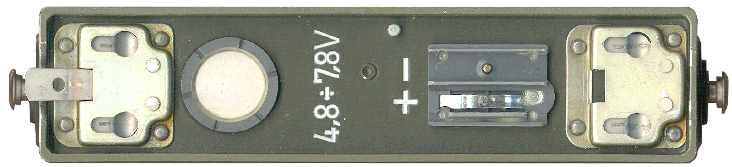
The top of the battery has
4 pins with notches that fit into the 4 "d" holes. the fifth pin near the right center end snaps into a hole in a spring locking the battery in place. The two contact electrical connector may be the same as the connector on the rear of the radio, only installed upside down. |
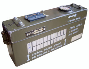 photo supplied by Daniel |
|
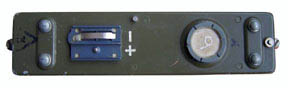 photo supplied by Daniel |
I think the round silver
item it to allow the gas from a venting battery to escape. It has the same look and feel as the ones on the FS5000 Spy Radio. But then why would there be one on the bottom of the radio? |
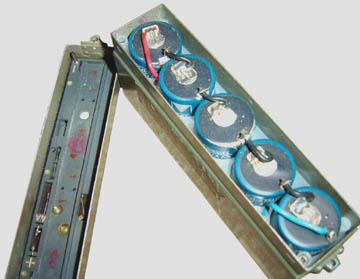 photo supplied by Daniel |
There's an alignment pin in
the upper left corner of the lid that mates with a socket
in the lower left corner of the box bottom. |
RF-10 Battery Box Empty Opened - holds
5 rechargeable D" cells (5 * 1.2 = 6 Volts)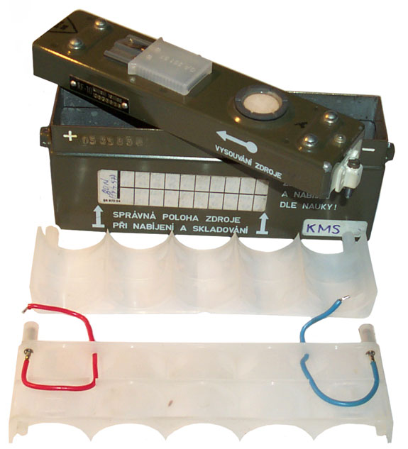 Thanks to Petr Ourednik for finding it for me. 16 May 2010 - Five Ni-MH "D" cells with tabs are on order. |
|
RF-10
Battery
Pack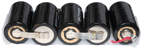 |
|
| Pin |
Description |
| 1 |
Chassis
Gnd |
| 2 |
|
| 3 |
Chassis Gnd |
| 4 |
|
| 5 |
|
| 6 |
Battery
+ |
| 7 |
|
| 8 |
|
| 9 |
|
| 10 |
|
| 11 |
|
| 12 |
|
| 13 |
Button
2 (no) * |
| 14 |
Mike
(when PPT pressed) |
| 15 |
PTT (nc) * |
| 16 |
Spkr
(260 Ohm DC) |
| 17 |
Button
1 (no) * |
| 18 |
Audio
Common |
| 19 |
Switch
Common * |
 |
 |
| RF-10
Audio Connector on Radio |
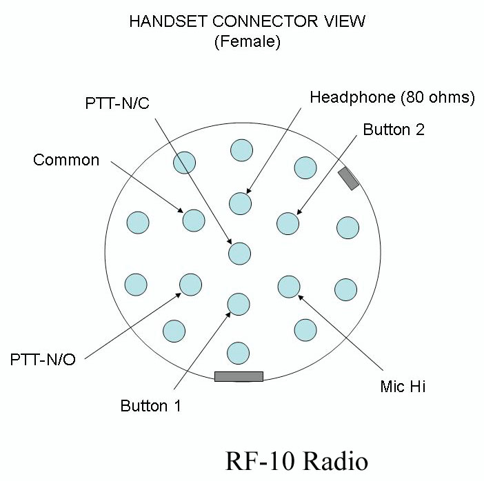
RF-10
Audio Connecotor on Handset cord |
OTOvy
stránky nejen o fOTOgrafování - Něco o RF 10 -
photos of the inside top and bottom and the manual as a single
file by user
[an error occurred while processing this directive] page created 26 Feb.
2008. List of all my web pages in alphabetic
order.
