Blasting Machines
© Brooke Clarke 2017 - 2024Army 10-Cap |
Galvanometer |
Polish
|
Mine Safety Appliance Co. |
Handi-Blaster HB-10 |
Claymore M57 Electrical Firing Device Claymore M51 Blasting Test Set  |
Description
U.S. Army 10 Cap Blasting Machine, Fidelity Electric Co.
Bethlehem Instrument Co., Inc. Blasting Galvanometer
Polish Blasting Machine
Handi-Blaster HB-10
Mine Safety Appliance Co.
Blasting Caps
Misc Blasting Machines
Polish Blasting Machine
M21 Training Land Mine
Photos
Army 10-Cap Blasting Machine
Blasting Galvanometer
Claymore M51 Blasting Test Set
Claymore M57 Electrical Firing Device
Polish Blasting Machine
M21 Training Land Mine
Trip Alarm
Manuals
Patents
Related
References
Links
Background
This is part of my interest in DC motors (and generators). Blasting machines (Wiki) were/are used to supply the electricity to fire blasting caps (Wiki).
In all cases the idea is to provide the energy necessary to fire an electrical blasting cap, like the Army M6. The first generation rack and pinion push down blasting machines depended on how hard they were pushed and if insufficient force was used not all the caps in a series wired string would fire. If the power gradually increases as the plunger is pushed down the most sensitive cap will fire thus breaking the circuit for the other caps. One possible solution was to add a switch at the bottom of the stroke so that only at maximum power the circuit is completed. Another approach is to use batteries, but in the field a dead battery is a problem and a very specialized battery is a much bigger problem since you and not get it at the local grocery store. The newest blasting machines make use of an energy storage capacitor. There are a number of approaches to doing this such as (1) an add-on capacitor for an existing generator type blasting machine, a high voltage battery + capacitor, a low voltage battery and step up power supply + capacitor, and a multiple cycle manual generator + capacitor where it takes a few cycles of the manual generator to fully charge the capacitor before firing.
It turns out that the system developed by Edgerton to use a strobe light in a W.W.II bomber for night photography was later used by the Manhattan Project to trigger the newly invented Exploding Bridge Wire that has much more precise timing than the conventional blasting cap. See: Kryton Tube & Edgerton.
Closely associated with blasting is the use of a seismometer. They are used in oil exploration to map sub surface structure. Also anytime there's blasting near man made structures or people there are government safety regulations that require monitoring with a seismometer.
eBay search (not optimum): Blasting Machine -(walnut,gloves,nozzle,sand,shot,industrial,ice,soda,sandblasting,dental,polish,media,gallon,fat)
Description
U.S. Army 10 Cap Blasting Machine, Fidelity Electric Co.
The handle turns a little less than 90 degrees and is spring loaded so returns to the starting position when released. This allows a switch to be fitted that only completes the firing circuit near the end of the twist to prevent a sensitive cap from firing early and disconnecting the other caps in a series string.
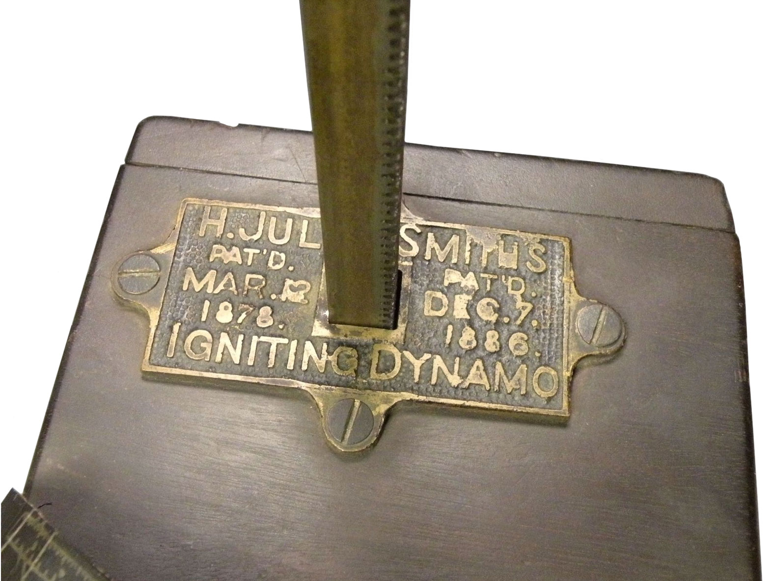
The label (see Fig 2 below):
10 Cap Blasting Machine
Capacity10 Electric blasting cap with 30 feet copper leg wires in series
Firing Instructions
Connect external circuit to binding posts: Twist handle vigorously to the right
CautionThis machine may lose capacity temporarily.
To Restore: Twist the handle vigorously a few times
Serial No. 27159
Fidelity Electric Co. Inc.
Lancaster, Penna.
As received then the handle was turned smartly, there was a loud noise consistent with a dry bearing. I'm guessing this has not been oiled since it left the factory. The method of testing a blasting machine in TM 9-1375-213-12 is to connect a 500 foot length of 18 AWG copper wire and the number of caps the machine is rated to fire and see if it does fire them. Not a very practical method.
An email to a friend:
The blasting machine is an Army 10 Cap. Meaning it will set off 10 series connected blasting caps. Could be for mining, or blowing up a bridge.
The old Push down type blasting machine had a problem in that as the speed started ramping up from zero at some point the most sensitive blasting cap would go off opening the series circuit, not a good thing. They then put a switch at the bottom of the box so when the plunger hit bottom the circuit was completed which more or less works, except if a wimpy push down happens to set off one cap in a string ruining the shot. The latest units use a capacitor that first gets fully charged (a light tells you that) then fires so the energy is well controlled.Testing
Some possible tests that can be done without caps. I tried connecting a few LEDs in series and to the blasting machine (after marking the terminals polarity) and the first time I twisted the handle it was clear that a switch completed the circuit near the end of the twist. The next time the LEDs were dimmer and the third time they did not light up. The current was too great and burned out the LEDs.
Voltage
1. Connect DMM in DC Volts mode, Press RANGE until no digits to the right of the decimal, press Min-Max. After a sharp twist press Min-Max to read Max voltage. About 60 Volts.
By connecting a 2200 uF - 50 Volt capacitor, observing the correct polarity and sharply working the handle it will charge to about 30 Volts.
Current
By connecting a DMM in DC Amps mode (press Range until only one digit is to the right of the decimal and them press Min-Max. Give a sharp twist then press Min-Max to see the peak current into a short. just over 1 Amp.
Oscilloscope
The best way to test may be with a scope and a load resistor, or better a number of different resistors.
Switch
Connect an Ohmmeter to the terminals and slowly twist the handle and notice that the resistance changes from an open circuit to a low value near the end of movement. Should be about 5 Ohms, but sometimes it's more like 144 Ohms. Maybe the switch needs to be cleaned? Ans. The screws under the test terminals were loose. When tightened the resistance measures about 5 Ohms.
Tried a two foot length of fine wire that measures about 0.2" as a bridge wire, but it did not fuse. Maybe need about 1.6 Ohm finer wire?
Bethlehem Instrument Co., Inc. Blasting Galvanometer
The battery is a specialized Silver Chloride cell, NSN: 6135-00-128-1632, Open Circuit Voltage: 1.0261.
The top scale is resistance in Ohms. Zero Ohms at full scale and 112 Ohms at half scale. 112 Ohms is the nominal internal resistance of the meter.
If the battery leads are shorted the resistance between the test terminals is 117.5 Ohms. Minus the two resistors (112 Ohms) leaves 5.5 Ohms as the meter internal resistance.
1.0261 Volts / 117.5 = 8.73 mA full scale. This is a safe current for a No. 6 blasting cap, so a guess would be that it takes more than 90 mA (10 X safe current) to set it off.
The bottom scale goes from 0 at the left (zero current) to 25 at the right (8.73 mA). What is the purpose of this scale? Let me know.
Polish Blasting Machine
Showed up on eBay from Poland for about $200. Then from a U.S. seller for a lot less as "CANNOT BE FIXED SOLD AS IS!!!!!!!!". I got one of these.
Will make some measurements to see if it's been demilled or ....
Blasting Caps
Also called Detonators (Wiki).
M6
Is the standard Army blasting cap and was/is a very common commercial blasting cap.
NSN: 1375-00-028-5224
Resistance < 1.6 Ohms
Firing: not more than 0.45 Amps with no more than 16.3 Milliwat seconds of energy applied for betwen 10 and 24 micro seconds.
Strings of M6 caps typically require about 1.5 Amps.
Testing: 200 to 210 mA current for 5 seconds will NOT fire.
From Federal Business Op
2350172 Electric blasting cap, Robert W Lawrence, Hercules Powder Co, App: 1940-05-17, W.W.II Pub: 1944-05-30, -
3040660 Electric initiator with exploding bridge wire, Lawrence H Johnston, App: 1944-11-08, W.W.II, Pub: 1962-06-26, - for use on Fat Man atomic bomb
also see Krytron , Rocket InitiatorMisc Blasting Machines
New style 50 Cap plunger type machine NSN: 1375-00-141-9495
M32 uses AC generator, rectifier and capacitor. 10 Caps.
M34 like the M32 except for 50 caps.
M51 Test Set NSN: 4925-00-999-3454
WB-411 type 1 Blasting Galvanometer NSN: 6625-00-539-8444
The Du Pont No. 0 Blaster is a spring wound generator with a release button (1909 catalog)
Atlas Handi-Blaster HB-10
This hand held blasting machine is of the capacitor discharge type. It uses a common 9 Volt battery as a power source.
4089035 Hand-held detonator, Don H. Smith, Tyler Holding Company, May 9, 1978, 361/251, 102/218 - HB-10 - - step up power supply converts 9 Volts to 100 Volts which charges capacitor that has resistor in parallel, so "Charge" button needs to be held down while "Fire" button is pressed.
Electrical tests:
1. With DMM in fixed DCV range & Min-Max mode when fired the voltage is 98 Volts.
2. With DMM in Ohms range, no buttons pressed, the resistance is 1.96 k Ohms.
3. With the DMM in Ohms range, and the Fire button pressed and held for a few seconds, 1.96 k Ohms.
4. With DMM in capacitance mode when Fire button pressed reads 289 uF.
5. The resistor that came with the HB-10 measures 689 Ohms.
The energy stored in a capacitor is 0.5 * C * V * V = 0.5 * 289E-6 F* 100 V * 100 V = 1.1445 Joules (Watt Seconds)
In patent 3537399 below they mention 210 WS for firing 150 blasting caps, so 210 WS / 150 = 1.4 WS for a single cap. This blasting machine is rated for 10 series EB caps.
Fig 1 Box
Fig 2 with instruction sheet & test resistor
Fig 3 Inside bottom 9V bat & charge storage capacitor.
patent 4089035
Fig 4
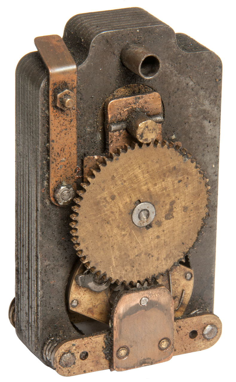
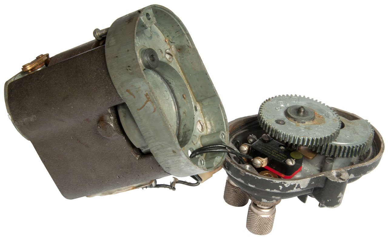
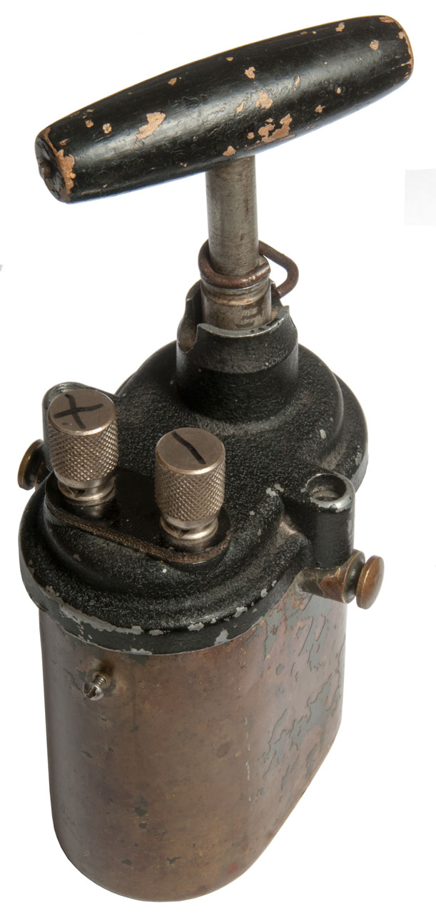
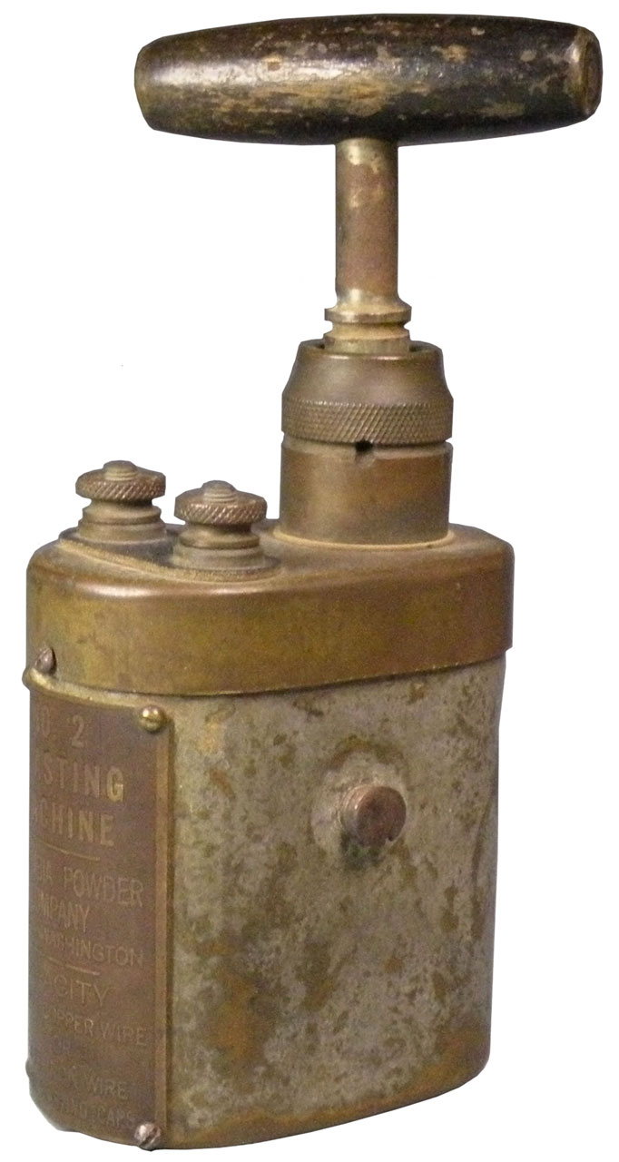
Mine Safety Appliance Co.
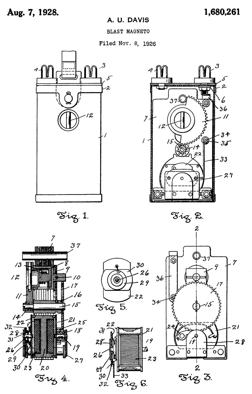
This appears to be a very old design hand held blasting machine. The case is copper sheet metal. The twister fits into the side, not the top like on more modern blasters, so maybe it predates the other blasters on this page. No, the generator uses laminated electrical steel instead of solid iron like on the earlier blasters. The patents (see below) have dates in the 1920s. The Davis No. 00 has a cylindrical body and top twist (See Hals Lamp Post-Davis No. 00). The Davis Single shot, per patent 1680261, is shown on Hals Lamp Post web page Davis Single Shot.
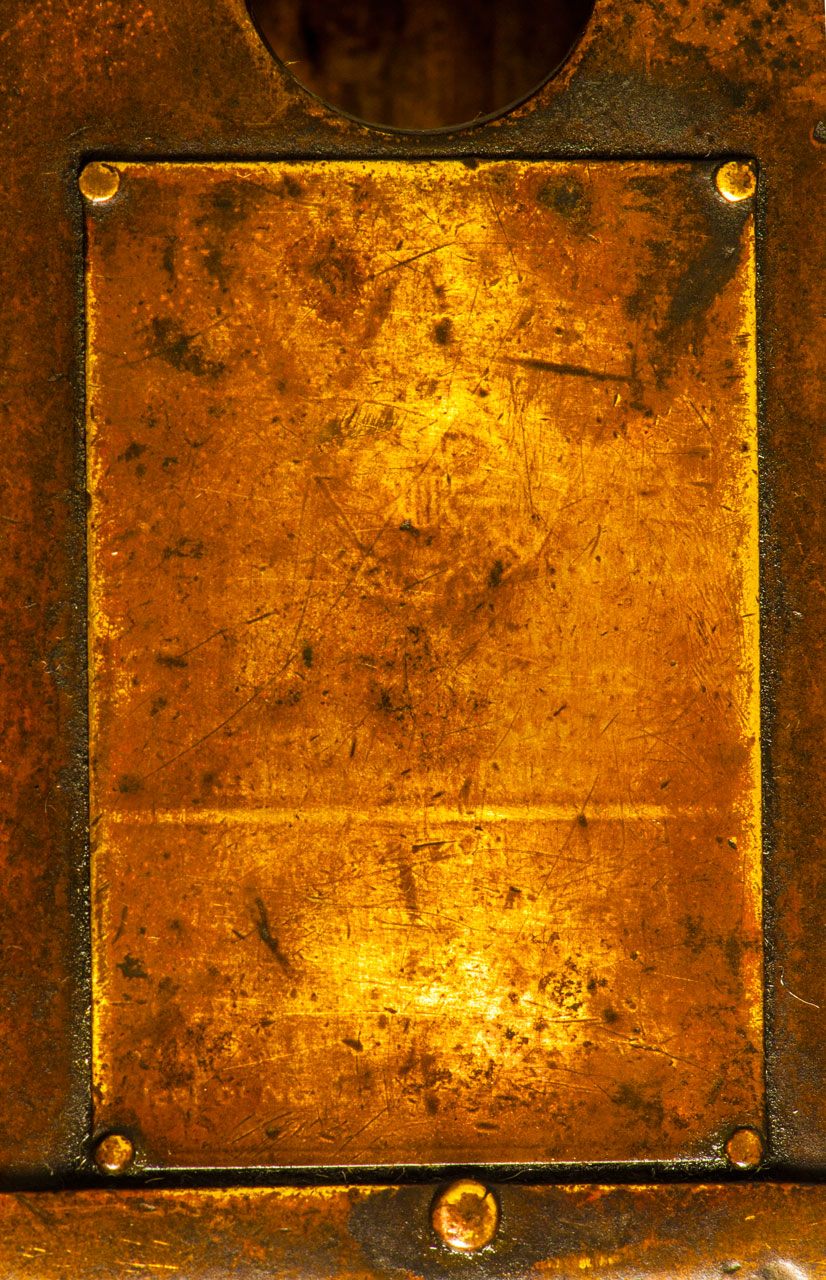
This was made by Davis Instrument Manufacturing Company of Maryland which I associate with weather instruments, like the all mechanical anemometer they patented in 1930 (1905444). My guess is that the label shown on the front side (Fig 3) is the Davis label and has worn away. The label on the back side (Fig 2) for Mine Safety Appliance Co. was added later.
Permissible
The Davis label might have said:
Single Shot Blasting Unit
Approval No. 1207 (Davis No. 000: issued 11/18/26) (30 CFR Ch 1, Part 24) Approval and Certification Center Part 24 Single-shot Blasting Units)
(Seal of Department of the Interior, Bureau of Mines)
Issued to the
Davis Instrument Mfg. Co. Inc.
Approved for Safety
Reliability and Durability
--------------------------
Caution
Not permissible unless used with rubber covered leading wires of length not exceeding 600 feet of
No. 14, 350 feet of No. 16, or ??? feet of No. 18 wire.
Fig 1
Fig 2
Fig 3
Fig 4
Fig 5
Fig 6 Label: Davis Instrument Mfg. Co. Inc.

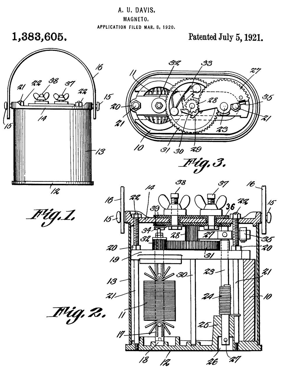
1383605 Magneto, Davis Alfred U, Davis Instr Mfg Company, Jul 5, 1921, 310/75.00B, 310/69, 290/1.00E -
Bottom drive
1680261 Blast magneto, Alfred U Davis, Davis Instr Mfg Company Inc, Aug 7, 1928, 310/75.00B -
Side drive


Photos
U.S. Army 10 Cap Blasting Machine, Fidelity Electric Co.
Fig 1
Fig 2
Fig 3
Fig 4 My best guess at Lube Points
two more on other side.
Fig 5 view under cover showing switch
Note a spring released when cover was opened.
In order to reinstall it you need to wind the handle until the ratchet holds it it place, then while holding the handle in that position install the cover. Note the top gear has a lever on it's axle that presses the micro switch and that lever needs to be on the actuator not above it prior to installing the cover.
Fig 6
Note small metal pin in end of handle. Why is it there?
It's not on the other end, see Fig 1
Fig 7 with 1/8 brass chain added.
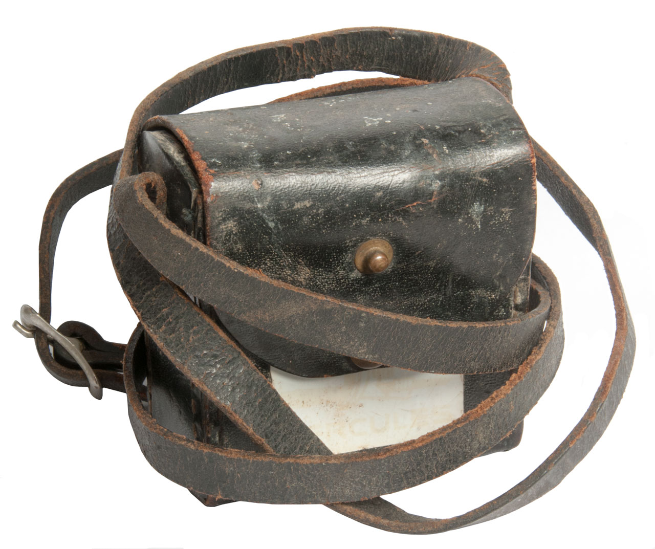
Blasting Galvanometer
Fig 1 Notice snap on front of leather flap.
Fig 2 Snap on leather flap snaps into back to hold open.
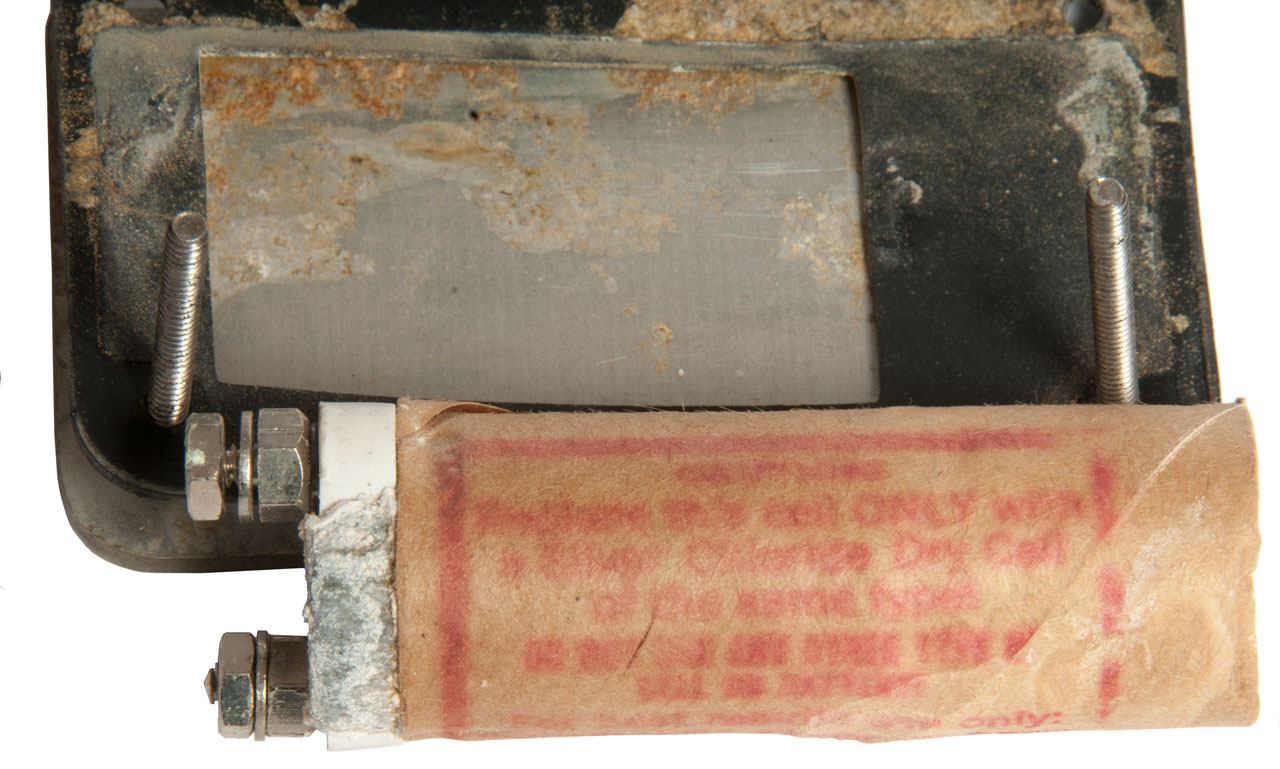
Fig 3 This unit was put in long term storage with battery installed. It corroded.
Fig 4
Fig 5
Fig 6
Fig 7 Notice wires going from main cavity into battery cavity in this and Fig 8. The resistors are marked 56 Ohms and measure within an Ohm of that value.
Fig 8 Note how 4 wires gown down into body.
Both screws under terminals were loose leading to
erratic resistance readings.
Claymore M51 Blasting Test Set
The Claymore Mine (Wiki) consists of the following components:
M18 Antipersonnel mine
M57 Electrical Firing Device
M51 Blasting Test Set
Description
This blasting circuit tester serves the same function as the Blasting Galvanometer. It's a component of the M18 Claymore mine (Wiki). My guess is that most of the parts that make up the M51 are the same as used to make up the M57 "Clacker" firing device.
I weighs just under a pound.
Operation
When connected to a blasting circuit and the lever is pressed the LED should blink indicating continuity. If the LED does not blink there's an open circuit.
But, if there's a short circuit this tester will not find it. The Blasting Galvanometer (above) will show the circuit resistance and so can detect shorts as well as opens.
Field Check
When the binding posts are shorted to each other and the lever pressed the red LED blinks.
A DMM in Diode test mode shows 0.651 Volts (@1 mA test current) in one polarity and an open circuit in the other polarity. This is NOT the LED but some other internal diode since applying half dozen volts current limited to 20 mA does not light the LED in either polarity.
Label:
Test Set Blasting M51
Lot FAC 2.1 Mfg 4/77
So even though this unit is 40 years old it still seems to be working.
Photos
Fig 1
Fig 2 There is another Claymore test device
that has male and female 2-pin connectors that
match the M57 firing device. It's connected between the M17 and the M18 to test the circuit.
2972949 Anti-personnel fragmentation weapon, Macleod Norman A, Filed: Jan 18, 1956, Pub: Feb 28, 1961, 102/401, 102/492, 89/1.1, 102/496 - M18 Claymore mine
H1390 Claymore training device, Carl J. Campagnuolo, Donald Gross,
Army, Jan 3, 1995, 434/11, 102/401 - MILES
10436558 Preformed fragment warhead having minimal fragment velocity distribution, Jason C. Gilliam, Army, 2019-10-08, - improved Claymore?
Claymore M57 Electrical Firing Device
This is used to detonate a Claymore mine.
Measures 1.1 Ohms across the output pins, but can not get a Max (peak) VDC measurement when handle is pressed.
Not sure why? Maybe it's defective?
Fig 1 Shown with the wire bail in FIRE position.
Fig 2 Shown with wire bail in SAFE position.
Manuals
TM 9-1345-203-12 (TM-9-1345-203-12.pdf) Operator's and Unit Maintenance Manual for Land Mines, October 1995, Para 2-3 M18A1 with Accessories (page=55) but not the M57.
The M57 Clacker: How it Works, 8:36 - This is the same mechanism as in the Bazooka M20 Impulse Generator.
M 57 firing device Part 2, 7:29 - he learned that the two magnets need to have parallel polarity so that the moving bar has one end North and the other end South.
Polish Blasting Machine
These are on eBay from Poland, but with a note that they are not functional. They didn't say that the gernerator had been removed. I.e. they have either been de-milled or were a poor design where the generator burned out.
The handle moves slightly more than 90 degrees. Instead of a Microswitch they just use a plunger and "U" shaped sheet metal strap for the switch. Care was taken to have low resistance. The label reads:
??TYP 12S1 160V 2A 80 (Ohms)
(can not read Polish writing)
The output terminals are marked (+) and (-).
Fig 1 with cap installed
Fig 2 with handle installed
Fig Inside showing missing generator


M21 Training Land Mine
M21 Mine: 9" diameter, 4-1/2" high, 11 pounds of HE (H6).
M607 (T1200E2) Fuze: 4" high. Can be used alone as pressure type or with tit rod.
Major Components
Technical Manuals
TM 9-1345-200 Land Mines, Headquarters, Department of the Army, 1964
CH 3 Antitank Mines, Section 1 active mines, Section 2 practice mines & fuzes (but not the M21)
Mines: M15, M21, M19, M6, M7
Fuze: M603,
Activator: M1, M2, M4, M120
TM 9-1325-203-12 Operator's and Unit Maintenance for Land Mines, HQ, Dept of Army, October 1995
Para 1-13 Mine, Antitank: HE, Heavy, M21 with Fuze Mine, AT, M607 (pdf page 1-17).
Para. 1-15 Mine, ANtitank, Practice: Heavy, M12A1, with Fuze M604.
Para 2-9 Mine, ANtitank: HE, Heavy, M21, with Fuze Mine Combiation, AT M606
Misznay–Schardin effect (Wiki)
A metal plate on the top of the mine works on this principle. It's a similar idea to the shaped charge (Wiki), except instead of a concave shape it's just a flat plate.
2587243 Cutting apparatus, William G Sweetman, I. J. McCullough, App: 1946-10-16, W>W>II, Pub: 1952-02-26, -
2763210 Shaped charges, Joseph H Church, Gregory J Kessenich, 1956-09-18, -
Also see Wiki: Explosively formed penetrator.
4649828 Explosively forged penetrator warhead, David Henderson, Chang-Sheng Ting, Avco, 1987-03-17, -
Description
The tilt rod has no provision to use a wrench for installation and I'm not strong enough to install it using just my fingers. Pliers would work but that's crude.
Need a 3/8-16 tap and die to clean up the threads on the tilt rod.
The training mechanism (Fig 3) consists of four push buttons wired in parallel and a battery plug buzzer.
Photos
Fig 1
Fig 2
Fig 3
Fig 4 M607 Fuze, M120 Activator, M26 Arming Wrench.
Fig 5 w/Tilt Rod
5207579 Antipersonnel training mine, Carl J. Campagnuolo, Army, May 4, 1993, 434/11, 102/404, 340/326, 273/372 - German S-mine (Wiki), US M16 (Wiki)
2398718 Percussion fuse, Rasmussen Olaf, GM, Filed: 1942-12-07 W.W.II, Pub: 1946-04-16, 102/272; 102/428 - "percussion fuses particularly adapted to be used to fire and explode land mines."
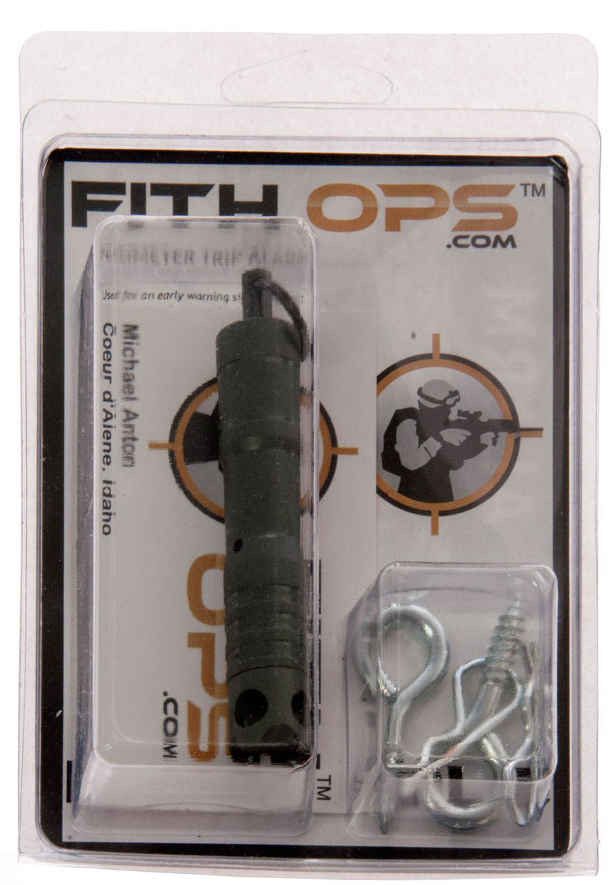
Trip Alarm
This idea is than when someone/something puts pressure on the trip wire it pulls a safety pin causing the firing pin to set off a shotgun (209) primer thus making noise. This only works is there's someone listening for the noise and if the intruder trips the wire.
Made by Fifth Ops - They also make one that fires a 12 ga shell with no barrel.
Photos
Fig 1
Fig 2
I have a number of web pages about what I call outdoor intrusion detectors:
Geophone Based Intrusion Sensors -
GSQ154 AN/GSQ-154 (V) Alarm Set, Anti-Intrusion, Restricted Area - uses circular modules
GSQ160 AN/GSQ-160 Detecting-Transmitting Set, Electromagnetic - uses antenna to sense intruders and to send alarm on different frequency. - also uses the same circular modules as the GSQ-154
GSS26 Alarm Set, Anti-Intrusion Restricted Area
USQ- Radio Frequency Monitor Sets & Related Equipment -
Intrusion Alarm Patents
Modular Outdoor Intrusion Sensors (REMBASS?)
PSR-1 - now on it's own page (July 2007) - seismic (geophone) based with audio output
Sonobuoy Based Outdoor Intrusion Alarms & Sonobuoys


Manuals
TM 9-1375-213-12 Operator's and Organizational Maintenance Manual, (Including Repair Parts and Special Tools List), Demolition Materials, March 1973 (with Change 12: 6 Nov. 1987).
But it does NOT talk about lube instructions for the blasting machines or talk about batteries for Blasting Galvanometers.
The Blasting Galvanometer uses a Silver Chloride cell with an output of 1.0261 Volts. It has #4 screw terminals.
TM 9-1375-203-12 Handle Operated Blasting Machine (have not found it - let me know)
Subcourse MM2605, Edition 4, US Army Ammunition Specialist MOS 55B, Demolition Firing Systems
Patents
The old style Army 10-Cap blasting machine may be patent 1771870 and the new style may be patent 2458687.
The 1771870 patent applies to theColumbia Powder Co - No. 2 blasting machine. Maybe it was the precursor to the Army 10-cap machine?
1771870 Blasting machine, Banzhof Charles P,
Fidelity Electric Co, Jul 29, 1930, 310/69
Columbia Blasting Machine No. 2
Patent date Jul 29, 1930
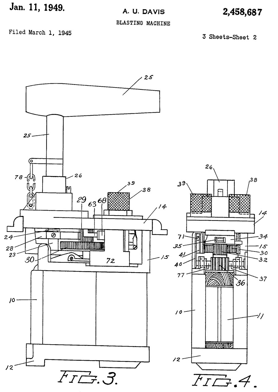
2458687 Blasting machine, Davis Alfred U, Jan 11, 1949
Fig 5 handle in rest position
Fig 6 just before switch closed
Fig 7 Switch closed


79268 Electric Fuse, H. Julius Smith, Jun 23, 1868 102/202.8 -
921049 Squib-igniter, Joseph A Wranischar, May 11, 1909, 102/202.8 - no open fuse in coal mine, much safer
93563 Electric Battery, H. Julius Smith, Aug 10, 1869, 310/309 -
173680 Electric fuses, H. Julius Smith, Feb 15, 1876, 102/202.14 -
173681 Electric fuses, H. Julius Smith, Feb 15, 1876, 361/248; 102/202.1 -
173682 Magneto-electric apparatus, H. Julius Smith, Feb 15, 1876, 310/70R; 310/54-
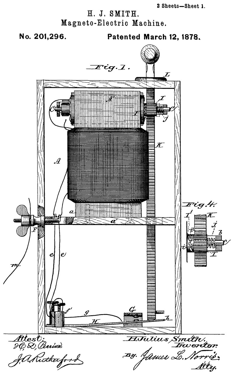
201296 Magneto-electric machines, H. Julius Smith, Mar 12, 1878, 310/69; 290/1E; 361/252 -
2081633 Method of and apparatus for firing explosives, Mcfarland David M, Atlas Powder Co, May 25, 1937, 361/252, 361/250, 310/69 - Push Down two switches on sides of rack.
2025907 Instantaneous circuit-closing device for electric shot firing machines, Konrad Schaffler-Glossl, Dec 31, 1935, 200/434 - for hand held top twist type machines.
Fig 1
Fig 2
201296 Magneto-electric machines, H. Julius Smith, Mar 12, 1878, 310/69; 290/1E; 361/252 -
353827 Dynamo-electric igniting-machine, H. Julius Smith, Dec 7, 1886, 310/69 - Push down type
My reading of the above two patents is that there is a normally closed switch that's opened at the end of the stroke. So the coils act like ignition coils generating a high voltage when the switch is opened. In the 1878 patent the switch is located at the bottom of the box, but it's been moved to the top of the box in the 1886 patent and a lid has been added. This was done because of problems with the bottom mounted switch which Julius attributed to moisture, but more likely was caused by pitting of the contacts when they sparked as they opened. This is why automotive distributors have a condenser across the points. Also it must have been hard work to press the rack down when driving a generator into a short circuit. Also a guide rod was added in the newer patent in an attempt to reduce friction (which may have been the effect of turning a generator into a short circuit). Note the machine pictured (from an eBay ad) does not have a guide rod so is based on the older patent, but has top mounted terminals like the newer patent rather than the side mounted terminals of the old patent.
2779276 Demolition firing device, Clary Jr Frank A, Jan 29, 1957, 102/392, 102/257, 102/419 - pressure actuated detonating device incorporating an electrolytic cell time delay means in which the cell locks the pressure actuated detonating device against 7 operation until the cell has been activated for a predetermined time.- Large diaphragm as pressure input
306478 Electrical Conductor, Perry G. Gardner, 1/2 to Giles K. Tinker, 1884-10-14, - This is just insulated wire, not part of a blasting cap.
3370220 Hand operated blasting generator, Bleich Kenneth E, Douglass Byron J, Universal Match Corp, Feb 20, 1968, 322/40, 310/83, 310/50, 310/69 - pumping hinged lever drives AC generator, rectified voltage builds op on capacitors, when at set threshold it is switched to output.
436023 Electric detonator or primer, Henry Julius Smith, Sep 9, 1890, 102/202.14 -
4381711 Hand-held shot tube detonator, Howard Lawrence, E.I.T. Corporation, May 3, 1983, 102/275.11, 102/200 - sort of a pen gun
495138 Magneto Electric Machine, J.N. McLeod, The Mcleod Electric manufacturing, Apr 11, 1893, 310/69 - push down/pull up type
534289 Art of blasting, Henry Julius Smith, Feb 19, 1895, 299/13 -
564437 Electric blasting-machine, James Macbeth, Jul 21, 1896, 310/69 -
694914 Electric apparatus for exploding mines, Sydney Evershed, Evershed Vignoles Ltd, Mar 4, 1902, 307/39; 310/155; 310/68B; 310/69; 310/83; 322/94; 322/99; 361/252 - heart is crank type telephone magneto
848153 Electrical blasting-machine, Lucien W Bowman, John H Lewis, Mar 26, 1907, 102/206; 102/202.1; 429/111 - box containing 4 wet cell batteries
877284 Electric apparatus for the ignition of mines, Otto Robert Percival Berglund, Walter Axel Wilhelm Emanuel Hjorth, Carl Ernst Ljungman, Jan 21, 1908, 310/69; 361/252 - heart is crank type telephone magneto
921049 Squib-igniter, Joseph A Wranischar, May 11, 1909, 102/202.8 - diagram shows phone magneto as power source
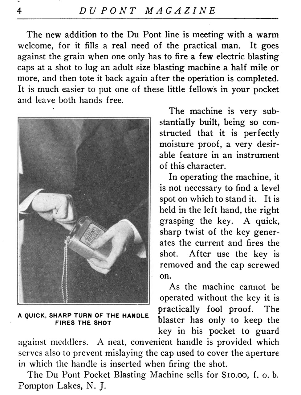
1072511 Dynamo-electric apparatus for firing mines, Konrad Schaffler Rekte Gloessl, Schaffler & Co, Sep 9, 1913, 310/75.00R - winding a spring the releasing, has the look of a hand operated machine, but not the same as the Army unit. This may be the pocket blasting machine advertised as just released by Du Pont in their 1913 magazine?
Note "a sharp twist" is not the wording if it was spring wound.
From 1913Du Pont magazine
From 1913 magazine
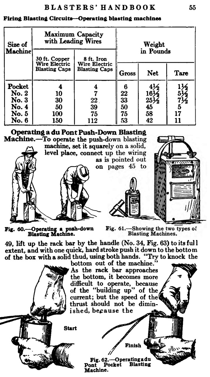
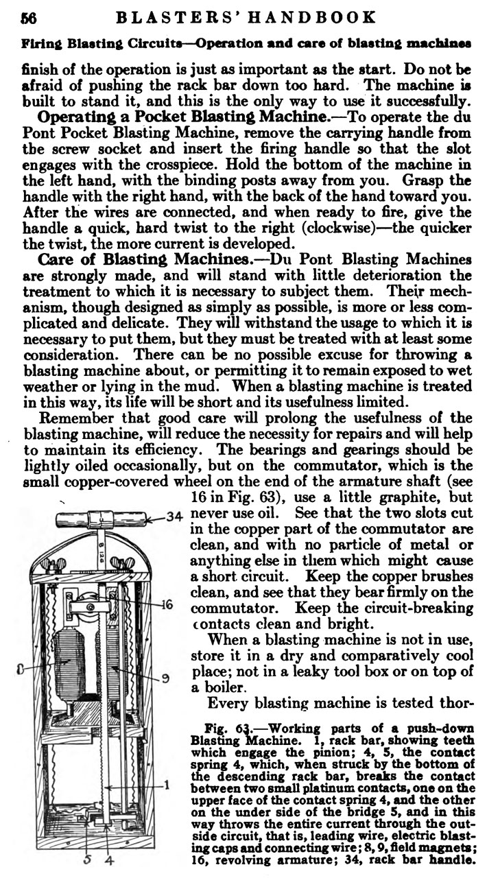
The directions for the push down blasting machine says:
"Try to knock the bottom out of the machine." As the rack bar approaches the bottom, it becomes more difficult to operate, because of the "building up" of the current; but the speed of the thrust should not be diminished, because the finish of the operation is just as important as the start. Do not be afraid of pushing the rack bar down too hard. The machine is built to stand it, and thei is the only way to use it successfully.
Later machines will add a switch so there is no resistance buildup and switch in the circuit just prior to the end of the stroke.
From 1922 Du Pont Blaster's Handbook
From 1922 Du Pont Blaster's Handbook
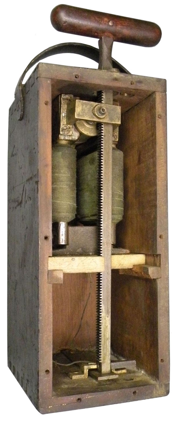
1209267 Electric blasting-machine, Ernest W Davis, Aetna Powder Company, Dec 19, 1916, 322/4; 322/83 - wooden box, crank type
1363585 Blasting-machine, George Haddow, Atlas Powder Co, Dec 28, 1920, 310/69; 290/1E - wooden box plunger type
1367608 Explosive powder, Arthur Langmeier, Hercules Powder Co Ltd, Feb 8, 1921, 149/8, 149/76, 149/69 - ammonium perchlorate explosive blasting powder
1431421 Blasting-fuse implement, Prince Harry, City Brass Foundry, 1922-10-10, - pliers for working with fuse
1479152 Dynamo-electric machine, Romaine Myers, California Cap Company, Jan 1, 1924, 290/1E; 310/69 - spring driven generator
1516009 Electric detonator, Harry L Grant, Djidics Alexander, Atlas Powder Co, 1924-11-18, - well sealed to work in deep wells,
1670419 Blasting gun, Mayer Walter S, May 22, 1928, 310/75.00A, - a pistol shaped device containing a spring powered generator, the trigger releases a pawl
1771870 Blasting machine, Banzhof Charles P, Fidelity Electric Company, Jul 29, 1930, 310/69 - early hand held type, symmetrical pin drive handle
1890445 Electric blasting machine, Asire Horace W, Martin Edward J, Perkins Wallace W, Du Pont, Dec 13, 1932, 310/69, 102/322 - push down type - multiple contacts on switch to minimize arcing
GB404181 Momentary Contact Switches for Electric Mine Firing Devices, Konrad Schaffler, Schaffler & Co., April 13, 1933 - has the look and feel of the Army 10-cap machine. The patent is all about the short duration pulse of current (10 to 30 mS long.
1999820 Delay cap, Henry E Nash, Hercules Powder Co Ltd, Apr 30, 1935, 102/275.9, 149/34, 149/108.4, 149/16, 149/37, 149/108.6, 149/15, 149/43, 149/79, 149/80, 102/202.13 -
2103432 Electrical firing device, Nash Henry E, Hercules Powder Co Ltd, Dec 28, 1937,102/202.3 - electrical delay cap for use with 440 VAC lines
Key:
1- Rack Bar
4 & 5 Contact Spring
8 & 9 Field magnets
16 revolving armature
34 rack bar handle
2129835 Electric shot-firing machine, Konrad Schaffler-Glossl, Sep 13, 1938, 310/69, 361/252 - requires generator magnetic field above some level in order to complete firing circuit by tipping mercury switch.
2280243 Switch, Lang Harold M, Stanolind Oil & Gas Co, Apr 21, 1942, 200/219, 310/69 - switch activated when plunger pushed all the way down completes firing circuit.
2313101 Blasting machine, Joseph Stuart, Hercules Powder Co Ltd, Mar 9, 1943, 310/69, 315/326, 315/76, 361/251, 327/261, 315/266, 361/248 - rack and pinion Push down type improved to provide high current, light bulb in box
2326696 Blasting machine, Stoddard Ralph N, Westinghouse Electric & Mfg Co, Aug 10, 1943, 361/251, 361/252 - rack and pinion push down type with AC generator & charge storage capacitor
2315823 Shunt for electric blasting caps, Smith Roscoe B, Hercules Powder Co Ltd, Apr 6, 1943, 102/202.3, 439/387, 102/202.12 - ships with cap for safety
2458464 Switch, Busacker John W, Perry Thomas M, Navy, Jan 4, 1949, 200/61.8, 200/61.33, 102/262 - un-shorting switch used in artillery shell.
2458687 Blasting machine, Davis Alfred U, Jan 11, 1949, 310/69 - Looks like the Army Liberty 10-cap hand held blasting machine.
2514401 Land mine, Lyle K Liljegren, Sec of War, App: 1942-08-17, TOP SECRET, Pub: 1950-07-11, - for tanks, includes low magnetic and inductive signature - cites & cited by
2524005 Spring powered electric generator, Gottfred Boe, Specialties Inc, Sep 26, 1950, 290/1.00E, 310/75.00R, 185/39, 185/10 - to fire squibs to allow escape from aircraft
2543754 Detonator testing device, Beach Ronald O, Mar 6, 1951, 324/502, 200/61.64 - for testing electric blasting caps
2617851 Electric impulse generator, Bisch James L, Bisch Ind Inc, Nov 11, 1952, 361/252, 307/108, 310/50, 310/154.2, 310/154.36, 310/36 - Explosion proof design for use in mines.
2618755 Electromagnetic impulse generator, Bussey William H, Roper Corp Geo D, Nov 18, 1952, 310/36, 361/259 - blasting or stove gas lighting?
2623922 Electric pulse-forming shot-firing device, Gary Muffly, Gulf Research Development Co, Dec 30, 1952, 361/251, 102/202.5, 361/252, 102/207 - has trigger output to start seismometer recording
2644117 Blasting machine, Schmitt Robert A, Swed James P, Williams Charles P, Du Pont, Jun 30, 1953, 361/248, 102/202.5 - for special caps that require over 10 amps to get enough heat to detonate.
2763812 Blasting machine, Mckinney Jr Charles D, Reitenour Jr Milton G, Hercules Powder Co Ltd, Sep 18, 1956, 315/205, 315/241.00R, 315/219, 315/241.00P - Battery drives vibrator - step up resonant transformer, rectifier and storage capacitor. Charge button, and fire button.
2784328 Contacting device for a dynamo-electrical igniting machine driven by a mainspring, Hans Schaffler-Glossl, Mar 5, 1957, 310/69, 200/18, 361/252 - energy stored in wind up spring then released.
2844747 Dynamo-electrical igniting machine, Hans Schaffler-Glossl, Jul 22, 1958, 310/69, 310/112, 361/252 - dual magneto for use in damp mines
2878752 Blasting initiator, Johnson Charles Russell, Swanson Merrill Edward, 1959-03-24, - can be assembled by machine instead of by hand.
2892128 Blasting cap electric firing system, Wolf Alfred A, Fidelity Instr Corp, Jun 23, 1959, 361/251, 102/322, 102/202.1, 361/252 - an add on capacitor charged from any type of blasting machine then disconnected from machine and connected to firing circuit.
2908847 Blasting machine, Williams Charles P, Witt Bickel Ferdinand De, Du Pont, Oct 13, 1959, 361/251, 102/218 - 525 Volt battery charges 50 uF to 1,500 uF capacitor
2916994 Electric blasting caps, Jr John J O'neill, Olin Corp, 1959-12-15, - cap to prevent ignition by radio while in storage.
2933653 Blasting machine, Carter Elbert P, Du Pont, Apr 19, 1960, 361/248, 102/202.5, 102/301, 102/218, 102/209 -a battery drives a saturable-core transformer which charges capacitor to meet mine safety rules
3056349 Method and apparatus for blasting, Mcfarland David M, Atlas Chem Ind, Oct 2, 1962, 102/206 - prevents cap damage from too much energy
3062143 Detonator, Savitt Jacob, Richard H Stresau, John P Weber, Armour Research Foundation, 1962-11-06, - means for controlling the delay time, less impact sensitivity,
3100447 Igniter squib, Robert E Betts, Army, 1963-08-13, - safe from HV arc between case and either lead,
3311788 System for firing series-circuit blasting caps, Faige Milton D, Filed: Jul 23, 1964, Pub: Mar 28, 1967, 361/252 -
3342998 Spring-driven electrical generator, Anderson Walter F, Fidelity Electric Company Inc, Sep 19, 1967, 290/1.00R, 185/37, 185/39, 102/207, 185/10 - for blasting
3343493 Arming and firing circuit, Aulds Darrell D, Scheibe Jr Harold R, Sep 26, 1967, 102/220, 327/473 - 28 VDC supply
3537399 Method and device for blasting, Miller Paul H, Atlas Chem Ind, Nov 3, 1970, 102/218 - 150 parallel caps, 210 to 400 Watt-Seconds
Calls:3538414 Capacitor-discharge device for blasting, Janoski Florian B, Atlas Chem Ind, Nov 3, 1970, 361/251 - AC mains powered for up to 150 parallel caps
2644117 Blasting machine, Schmitt Robert A, Swed James P, Williams Charles P, Du Pont, Jun 30, 1953, 361/248, 102/202.5 - for heat type caps, uses vibrator supply
2892128 Blasting cap electric firing system, (See above)
2908847 Blasting machine (see above)
2961583 Detonator circuit for permissive explosion shot firer, Sorensen Andrew J, Femco Inc, Nov 22, 1960, 361/251, 315/241.00R, 307/110 -
3011096 Electrical timing circuit, Perdreaux Jr Rene J, Stanley Wallack, Nov 28, 1961, 361/251, 310/301, 307/110, 327/261, 102/219 - just adds delay
3141114 Blasting machine, Jenkins Richard H, Wieber Elmer H, Vibration Measurement Engineers, Jul 14, 1964, 361/251, 200/50.37, 102/206 - battery - capacitor type
3167014 Bridge wire for producing high temperature explosion, Louis Kopito, Baird Atomic Inc, Jan 26, 1965, 102/220, 102/202.7, 102/206, 431/357 -
3288068 Triggered exploding wire device, Jefferson Donald E, Kettenbach Carl W, Sec of Navy, Filed: Apr 30, 1964, Pub: Nov 29, 1966, 102/218, 102/202.7, 60/39.821
3717794 Blasting device, Higgins R, Yates P, Explosives Corp America, Feb 20, 1973, 361/251, 361/248 - 2 series connected batteries (maybe 22-1/2V each) and firing capacitor, no active circuitry
3978791
4089035 Hand-held detonator, Don H. Smith, Tyler Holding Company, May 9, 1978, 361/251, 102/218 - HB-10 - step up power supply converts 9 Volts to 100 Volts which charges capacitor that has resistor in parallel, so "Charge" button needs to be held down while "Fire" button is pressed.
436023 Secondary explosive detonator device, Virgil F. Lemley, Glenn E. Seay, Perry B. Ritter, Systems Science and Software (Maxwell Labs), - low voltage, slapper (Wiki),
4788913 Flying-plate detonator using a high-density high explosive, John R. Stroud, Donald L. Ornellas, USDOE, App: 1971-06-01, TOP SECRET, Pub: 1988-12-06, - improvement over the Exploding Bridge Wire (Wiki) which has the following problems: "However, because the detonator requires a low density intermediary explosive, they are to as vulnerable such factors heating aging vibration, and contamination, as well as the fabrication process which requires extreme precision."


Related
E.I.T. Corporation -
VSV-Engineering - Blasting machines for insensitive detonators -
Weapon Launched Grapnel Hook (WLGH) - designed to clearing trip wire land mines, but might work for installing wire antennas in trees.
References
Ref 1. Atlas Electrical Blasters Handbook - mostly about Ohm's law (Wiki), but also some good information in a plot of current vs. time.
Samuel Colt's Submarine Battery: The Secret and the Enigma, Philip K. Lundeberg, Smithsonian Institution, 1974 (available free on line) - here "submarine" means under water, and battery means an array of gunpowder charges in wooden kegs, similar to the idea an an artillery battery (Wiki). The idea was to fire black powder using electricity. There were two applications for this technology, one was to protect harbors from enemy ships and the other was to trigger underground explosions like in mining operations, so very much related to blasting machines. This article uses words that make clear the type of electricity, but does not say differentiate them. Electricity was a new thing back then and so there appeared to be different kinds of electricity. One was "static" electricity and it could be collected in a Leyden Jar (Wiki) which today would be called a high voltage low leakage capacitor (Wiki). The electricity thus captured could be used to make sparks or deflect an electrometer (Wiki) but could not be used to light a lamp, actuate a solenoid, or run a motor. To do these later things requires a Voltaic pile (Wiki) or generator (Wiki). In the article they talk of two different ways to igniting black powder (Wiki), one using a Leyden Jar and a spark gap in a tube if very fine gunpowder. The other way used a fine wire that was heated by the current from an electrical battery (here battery means a source of electricity). Note the energy stored in a Leyden Jar typically is not enough to melt a wire.
There was a problem in that most water contains dissolved minerals and so is an electrical conductor. So any submarine (underwater) wire must be well insulated to prevent loss of current.
In 1831 they were trying to use a Leyden Jar type system to ignite combustible gas for rock blasting, but there were numerous fatal accidents, so a better system was desired.
"Scarcely less important than the galvanic machine incorporated in Hare's (1833) rock blasting system was a tubular firing device that he fashioned for detonating individual charges sealed in selected crevasses or drill holes. Consisting of a cylinder of tinned iron fitted with ignition wire and a wooden plug packed with fulminating powder, this simple galvanic fuse suggested additional applications to Hare, who observed: "It must be obvious that in all cases of blasting under water, the plan of a tin tube, and ignition by a galvanic circuit, must be very eligible."
Ref 2. FM 20-32, Landmine Warfare, 30 Sept 1992,
Part 1 Conventional Mine OperationsRef 3. Blasting Machines: Not Just for Wile E. Coyote, 28:47 -
1. Conventional Mines
2. Mine Warfare Principles
3. Standard Pattern Minefield
4. Row Mining
5. Reporting and Recording
Part 2 US Scatterable Mines
6. Scatterable Mines and Mine Systems
7. Responsibilities, Marking, Recording & Reporting
Part 3 Counteroperations
8. Countermine Operations
9. Minefield Reduction
10. Route Clearance
11. Reactions to Scatterable Mines
Part 4 Special Mining Operations
12. Speical Mining Operations
13 Booby Traps
History of explosives: Gun Cotton (Wiki), Nitroglycerin (Wiki), Dynamite (Wiki), Collodiion (Wiki); Movies :Wages of fear (IMBD, Wiki), Sorcerer (IMBD, Wiki); Blasting Cap with fuze (Wiki), Blasting Cap, electrical (see: 436023), Bridgewire (Wiki),Ref 4. Detonators, 51:53 - Blasting Caps
@13:23 Dynamo-electric igniting-machine (see: 353827) i.e. Blasting Machine.
@13:41 5 Types of Blasting Cap:
1. Fuze@16:37 Blasting Cap Primary Explosive: Nitromannite (Wiki), Diazodinitrophenol (Wiki), Lead Styphate (Wiki), Lead Azide (Wiki),
2. Electric Match Head (model rocket igniter)
3. Electrical solid pack hot wire in primary explosive (patent 306478 is just for wire)
4. Exploding Bridge Wire (From Manhattan Project, See: 3040660)
5. Slapper Detonator (Wiki) (see: 4788913)
@16:45 Blasting Cap Secondary Explosive: PETN (Wiki), RDX (Wiki)
@17:01 Exploders Dynamo Mk VII -
@22:25 Exploder-Dynamo Condenser Mk II (@25:11 Schematic: MK 3)- AC generator, step up transformer, rectifier, Capacitor; accessory: Test Device (not a doubler)
@27:52 Battery Powered Exploder
Ref 5. CIA-RDP78-03642A000600020001-2: Interior Assemblies of Blasting Caps (pdf), - other CIA documents on "Blasting Cap". - many interesting papers
Links
PRC68, Alphanumeric Index of Web pages, Contact, Products for Sale
Page Created 2017 August 23