TS-2839/GY Audio Test Set
NSN 6625-12-306-3955
© Brooke Clarke 2015
NSN 6625-12-306-3955
This is a German audio test set from the late 1980s. Took a few months to arrive from Helmut Singer. I just received it and so don't have a full understanding of what it does. The manual and panel markings are in German.
Based on the low serial number (33) and lack of a contract number I'm guessing this was part of a pilot run rather than some fielded equipment. A NSN search turns up a handful of hits also indicating that this is a prototype or low production item.I've heard these were made in quantity and used long after the Korean conflict since many German military radios continued to use the U-77 series audio accessories.
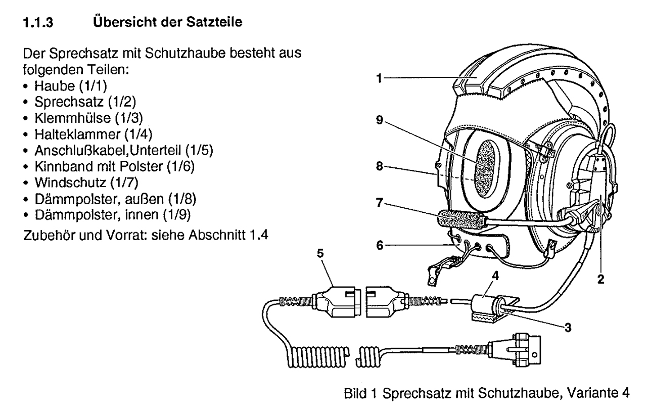
Military audio accessories have features that are common to the application. For example combat vehicle crewmen typically have a helmet that holds the earphones and either a throat or boom microphone so both hands are free. Also there needs to be a way to direct the microphone to either the radio or the intercom. In addition there needs to be a quick disconnect for emergency vehicle egress. The H-161 is a combat vehicle headset.
These headsets can be separated into three parts: The cable that connects to the radio (or intercom) and the bail out connector, the cable between the bail out connector and the switch box, the cable from the switch box to the headset proper.
This TS-2839 test set can test the above cables, the switch box and the microphone and speakers in the headset.
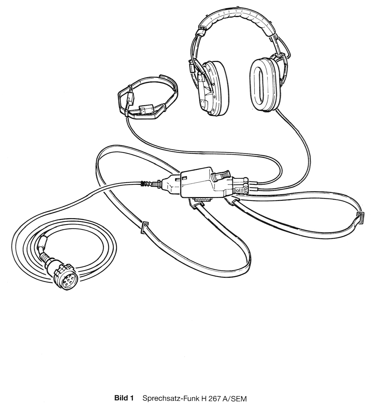
H-267 combat vehicle headset
H-280 Headset
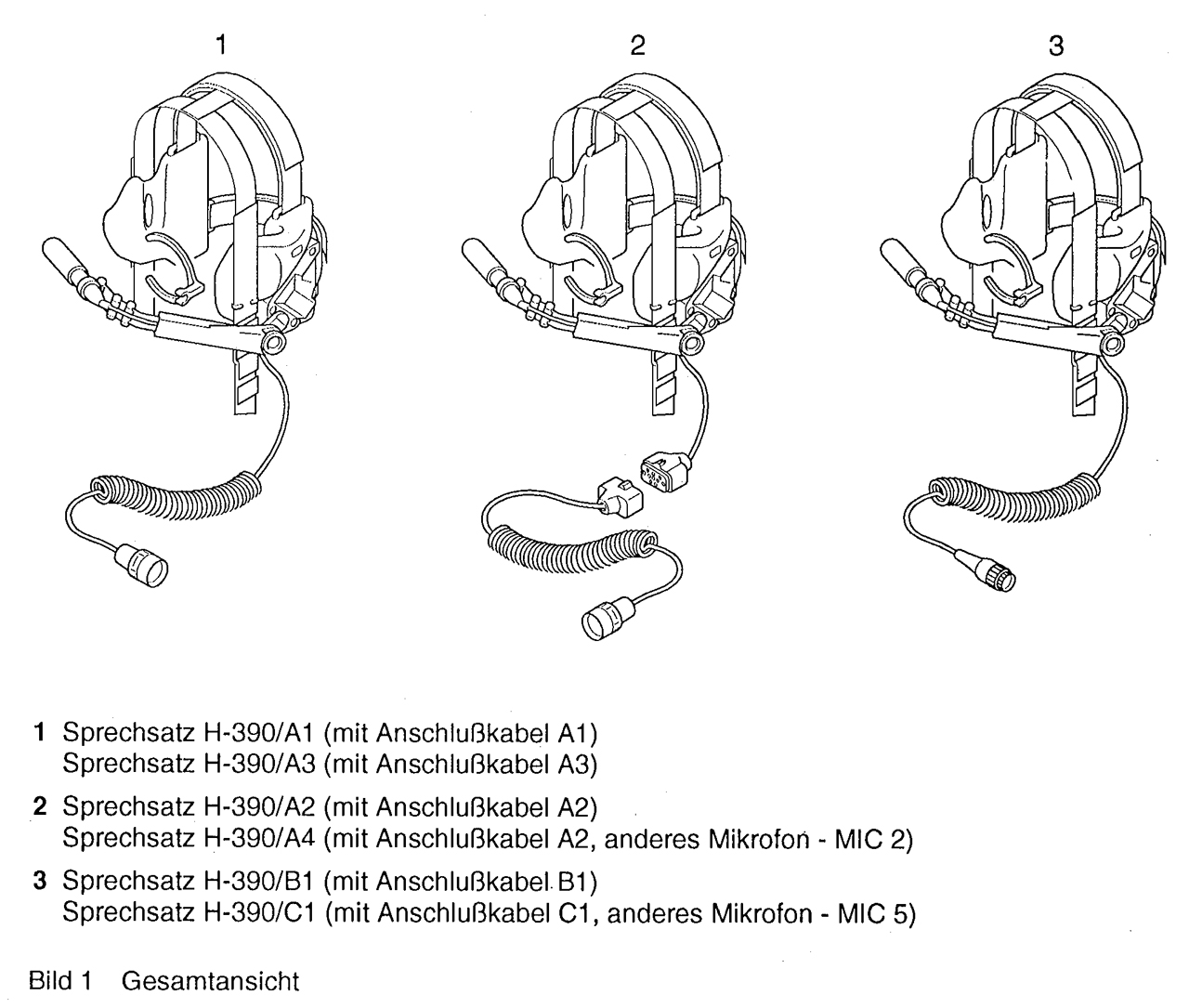
H-390
The panel is divided into sections and they are from left to right:
24 VDC Input Power
The three items are: power cord terminated with large spade lugs, red and green LED, S1 On/Off/Test toggle switch
Kabelprufüng (Cable Test)
Note the front panel (Fig 3) legend which shows a line with dots adjacent to the column of red and green LEDs for each of the connectors. Which shows which LED are applicable to that connector. For example the UG-77 10-pin AUDIO connector has dots next to rows: A, B, C, E, F, J & K. Also the same line goes to other connectors in the Cable Test area showing what cables can be tested that have different connectors on each end.
Note that which LEDs (pin letters) are active depends on the connectors on both ends of a cable. The maximum number of paths is set by the end connector with the lowest number of pins and the total number of pins may be even lower than that. But in any case for an specific cable the dots on the line associated with those two connectors show the active pin letters.
Jacks
No.
Type
Pins
J1
?
7
P2
?
SEM-52
10
J3
P3
P10
?
9
P7
J2
U-77
20
P1
?
8
Missing is the type U-229 Jack! This is probably why this unit is on the surplus market since most modern equipment uses this connector.
The U-77 is a Korean Conflict era connector. Note this connector is associated with handsets like the H-33 which use a carbon mike. So maybe the other cable ends associated with this connector (P10, P1 &P3) are also carbon mike vintage connectors?
S2 Function
S2 is a three position switch where the center position is Off, i.e. The Cable Test section is not active.
On: continuity is being tested, Red is an open and Green is a good circuit.
TEST: without any cable connected turns on all the green LEDs.
See Fig 4 below with the test set powered (S1: On), a 10-terminal male-female cable connected and S2: On.
Terminals labeled "B" and "E" have red LEDs indicating that they have open circuits.
LEDs
There are 11 rows of LEDs with each row containing a red and green LED.
The rows are labeled: A, B, C, D, E, F, G, H, J, K, L (note common military idea of skipping I which can be confused with 1 and l).
Sprechsatzprufüng (PTT Test)
My best guess is that this area is for testing the PTT function, but the LED table seems to be doing something with the microphone circuit. Maybe that's related to the section just to the right that has to do with Microphone test (S3 is common to both sections).
Jacks
No.
Type
Pins
Label
J4
7
H155/C
H-390/C
SEM-52
J8
DIN
7
-
J5
10
H-155/B
H-390/B
P8
9
-
J7
8
H-267
H-280
J6
U-77 10
H-33
H-155/A
H-267
H-280
H-390/A
Switches
S3 is on the line separating the PTT Test area from the Microphone Test area. It has On/Off/Test positions
S4 ( 1kHz tone) in inside the PTT Test area and has positions On/Off/Momentary with On corresponding to "R" and momentary corresponding to "T".
LEDs
There are 5 rows of LEDs with green and red on each row.
The translations are my best guess.
Row
Verstärker (amplifier)
Mik.-Sender (Microphone keying radio)
Mikrofon-BV (Microphone keying intercom)
Sende-Taste (PTT to radio)
BV-Schalter (PTT to intercom)
Mikrofonprufüng (Microphone Test)
LEDs
At the top of the area are a red and green LED with the label pegel (Level).
When you speak into the microphone the LED should flicker.
Note: If it's a noise cancelling microphone, like the M-80 or H-250, then the mike needs to be toughing your lips to prevent your voice from being canceled.
Jacks
There are four jacks.
No.
Type
Pins
Label
P4
Mike
Element
2
H-33
H-155
P9
3
H-390
P5
3
H-280
P6
3
H-267 (Swedish web page)
Switch
S3 is on the line separating the PTT Test area from the Microphone Test area. It has On/Off/Test positions
Test Jacks
There are four banana jacks:
Jack
Color
Label
J10 Green Hörer-prufüng
(Headphone-test)J11
Blue
J11
Blue
Durchg-prufüng
(passage-test?)J12 Black J13
Yellow
Test
This is not at all clear.
Note in the lid there are red and black test leads with matching red and black probe tips.
Fig 1 Case closed
Label:
Vers. Nr. (NSN) 6625-12-306-3955 (Handset Tester)
Sprechsatz-Pruefgeraet (Audio Tester)
Ser. Nr. 00033
Auftr. Nr. (contract No.) <blank>
Telemit Electronic gmbh,
8000 Munchen 45,
mfr code D 0800
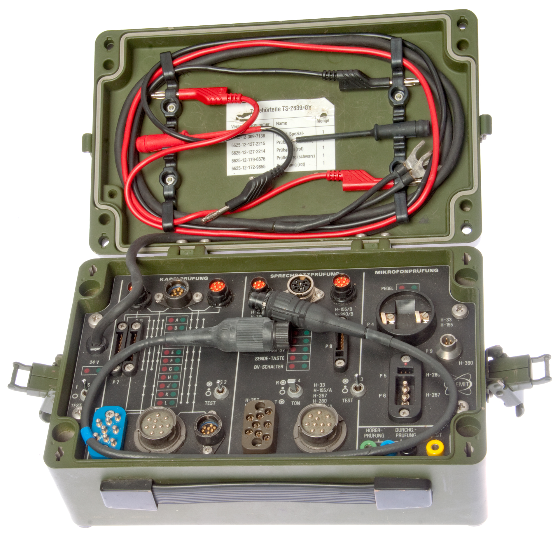
Fig 2 Case open
Loose cable has 10 terminals and is an extension.
Fig 3 Front Panel
Fig 4 Powered (S1:on) and with 10-pin cable connected (S2: On)
Hörer
Vorläufer
1 Beschreibung
2 Bedienung und Pflege
3 Truppeninstandsetzung
5 Ersatzteilkatalog
Audio Connectors & Military Cloning - Fill - Retransmission
Beltone 12D Audiometer
Funkanpaßgerät WT-FM-E1 AP01 (maybe a wireline to radio adapter?)
General Radio Sound Measurement Instruments
GRA-39 Radio Set Control, C-2328 remote unit & C-2329 local unit
H-33 Handset
HP204 HP 204B Audio Oscillator from HP 3350 Carrier Test Set (AN/USM-181 Telephone Test Set
HP241A HP 241A Audio Oscillator w/Radio Buttons
Military Audio Accessories
Audio Patch Panel
SEM 52 German Squad Radios
Signal Design, Inc. 65630 Audio Recorder RD-609/TSQ-164 Communications Recorder
Telephone - Telephone patents
TS-585 Audio Level Meter
U-229 Audio Accessories
U-229 Pin Out by Function
PRC68, Alphanumeric Index of Web pages, Contact, Products for Sale