"The AN/KY-38 Secure Voice System is a member of the NESTOR equipment family, which consisted of the KY-8 Vehicular unit, the KY-28 aircraft unit and the KY-38 "manpack" unit." . . . from the KY-38 (Nestor) - Crypto Machines Web pageThe KY-28 was the airborne Nestor box used the KYK-28 control panel.
"In 1964, production of the Nestor series of enciphered voice communications (KY-8 vehicular mounted, KY-28 aircraft, and KY-38 manpack) was begun, but over a year passed before the KY-8/38 reached Vietnam in sufficient numbers, and even then few existed below battalion level. The Nestor equipment was sensitive to humidity and heat, and aircraft carrying KY-28s required frequent refitting. However, most of the problems involved the KY-38 because of its weight and bulkiness. The initial solution was to divide the communications gear, connected by a cable between two soldiers. During combat, the weakness of such an arrangement was obvious."
Ref The Most Secret War, govt. printing office, ISBN 0-16-051284-0, page 74.
"Initially reluctant to produce a cryptographic device for the combat infantryman that would undoubtedly be captured, the National Security Agency in January 1966 nevertheless agreed to develop a security device for portable radios. The National Security Agency and the U.S. Army Electronics Command designed the PRC-77, a modified PRC-25 that could be connected to the speech security gear." pg. 400
...
"In late 1967, after 15,000 PRC-25s and 7,000 models of the VRC-12 series radios were in the hands of American troops, and 9,000 PRC-25 models were being issued to the South Vietnamese Army, the Electronics Command produced an improved version of the PRC-25 even before the first PRC-25's had been sent to South Vietnam, the laboratories at Fort Monmouth were working to replace the power amplifier tube, the only vacuum tube in the set, with solid-state circuitry to lessen power requirements. They also added filters to reduce interference that later plagued communicators on crowded retransmission sites such as Nui Ba Den.
In December 1965 a means for connection with a security device, called an X-mode capability, was added to the specifications, and the new radio was designated the PRC-77. Although the Army had tested and produced the new radios to give the National Security Agency time to correct deficiencies in the companion security devices. Having had difficulties linking components of major assemblies in South Vietnam even when they were transported together, the Army wanted to issue the radios and security devices, the KY-38's (KY-28's for aircraft use), at the same time. The most serious problem encountered when the radios were finally fielded was the breaking of the cables connecting the radio to the security device. Then 500 replacement cables which had been quickly fabricated in a depot in the United States were lost in the crash of a cargo plane. The National Security Agency resolved another problem by developing a pressure-relief valve to preclude the buildup of hydrogen gas from the KY-38 batteries that had caused several KY-38's to explode after prolonged operations. By December 1968 modifications were completed, and over 9,000 new radios were in the hands of American combat radiomen." pg 448
Ref. A Test for Technology, John D. Bergen GPO, 008-020-01035-9
Footnote 10 from An Analysis of the Systemic Security Weaknesses of the U.S. Navy Fleet Broadcast System, 1967-1974, as Exploited by CWO John Walker by Laura J. Heath, MAJ, USA M.S., Georgia Institute of Technology, 2001
An example of a failed project was the KY-28, a voice radio encryptor designed during the Vietnam War for use in fighter aircraft. More than $110 million was spent to develop and field KY-28s, and over 2,200 were manufactured and installed. Combat pilots refused to use them, however, because the lag between transmission and receipt of the message was a dangerous distraction in combat. The result was that US air to ground communications remained unencrypted and vulnerable to enemy exploitation throughout the war. See Bamford, 95.
My use was the RT-524, AN/VRC-46 , annoying VC & NVA with Naval gunfire.  KY-8 tended to overheat so all the RX was the sync pulse and squelch rush, no audio. The field fix was drilling the top of the KY-8 case full of holes and mounting two (2) cum-shawed Rotron fans on top(non-authorized field change). Heat problem solved, CMS violated, but 5" on target during TET '68.  Off Hue, Danang, Qua Viet, Jan-Feb 1968, USS Buchanan DDG-14
EdZ

We used a block of ice when we could get one.................   Usually in an ice chest filled with soda's of course.    RICH  WA6KNW
KYK-28
The key is loaded with a KYK-28 which contains a lot of pins set for various depths and a couple of larger plungers to compress the zeroize springs.
This is a digital voice encryption device (not a scrambler) used with wide band military radios, either VHF low band (30-88) or UHF (225-400).Initially made in conjunction with the VRC-12 Series (RT-246, RT-524, R-442)of vehicular radios. Later the PRC-25 was redesigned so it too could be used. The upgraded PRC-25 was called the PRC-77. Probably 18.75 k bits per second digital data either di-phase or base band. This is different from the 16 k bps used with the VINSON KY-57.
The NESTOR equipment interfaces directly with the 10 pin X-mode connector on the VRC-12 series radios (called the POWER connector on the PRC-77). VINSON equipment needs the junction box installed in the MT-1029 when used with vehicle mounted radios. So the assumption is that there's a cable that connects between the 26 pin connector on the KY-38 and either the 10 pin X-mode connector or the 14 pin POWER connector and no other boxes are needed.
The KY-38 is used with the PRC-41A (225 - 400 Mhz) (not PRC-41) by means of a short CX-10831/PRC-41A cable. How does the "A" version of the PRC-41 differ from the no change version? Maybe crypto related?
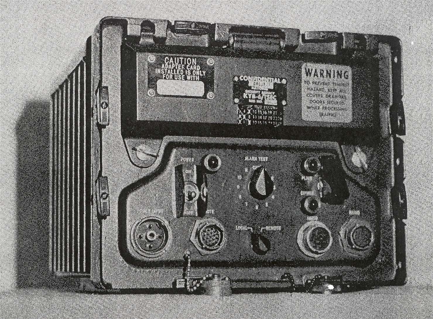
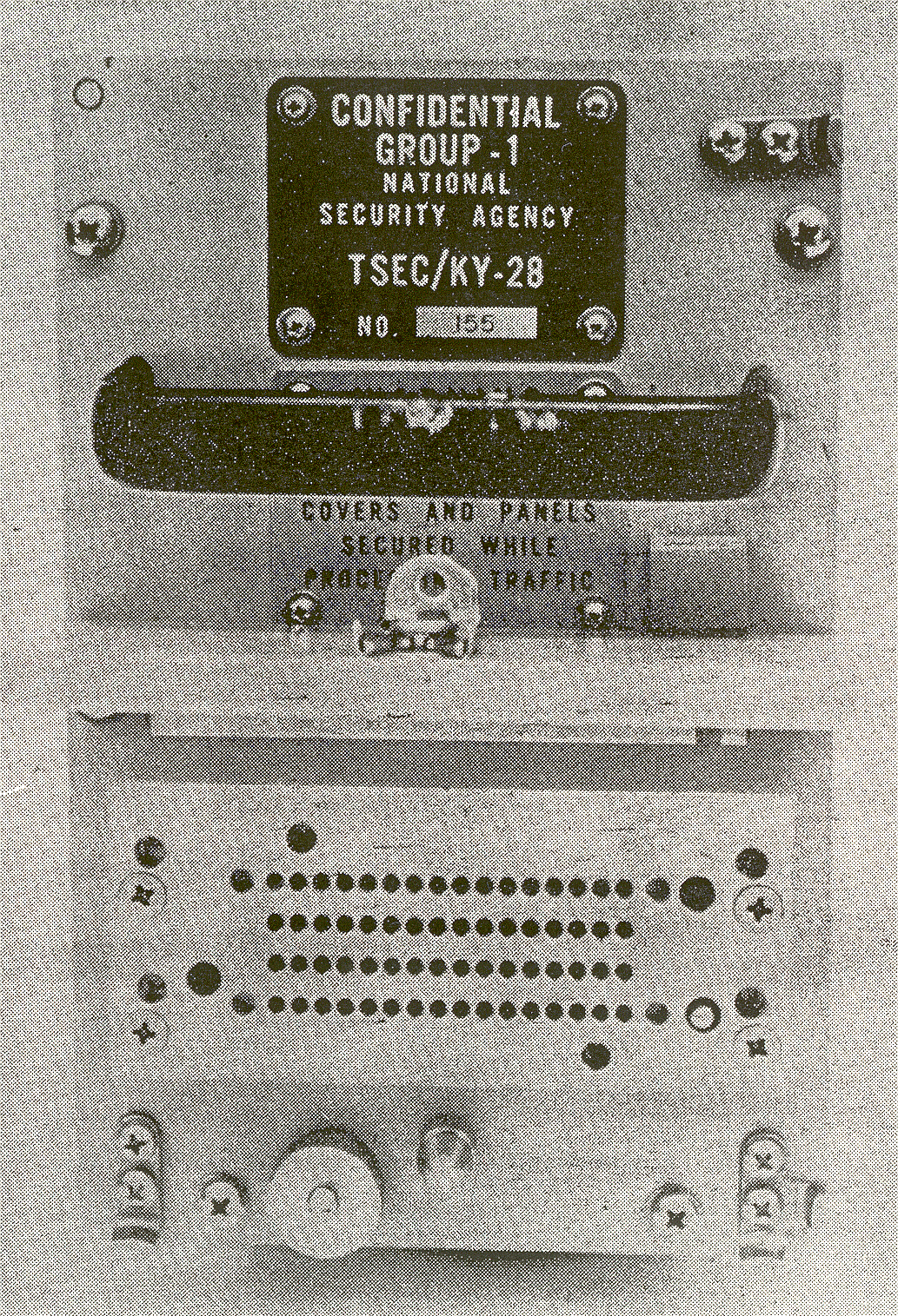
Labels
The transit case is labeled:
CONFIDENTIAL
National Security Agency
98230 ON015057
Unclassified when all classified
materials are removedThere does not appear to be a nomenclature plate on the KY-38 itself. There is a stick on label:
Certified
Crypto Repair Facility
Navelex SD
Date 2-11-86 Init
Navelexsd 2652/13/74The Equipment mod record has 27 numbered squares and only 5, 6, 10, 15, 20, 21, 22, 24, 26 and 27 are NOT marked with an "X".
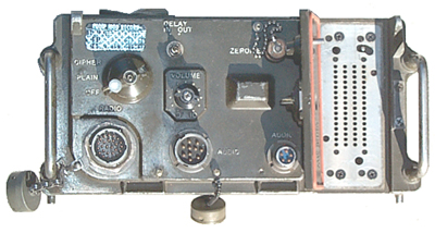
Connectors
There are 4 connectors on the front panel:
RADIO is a Brundy 16-26 with 26 male pins, the cap is marked Bendix 7217 MS3181-16N and the connector body Brundy BT070 16 26P
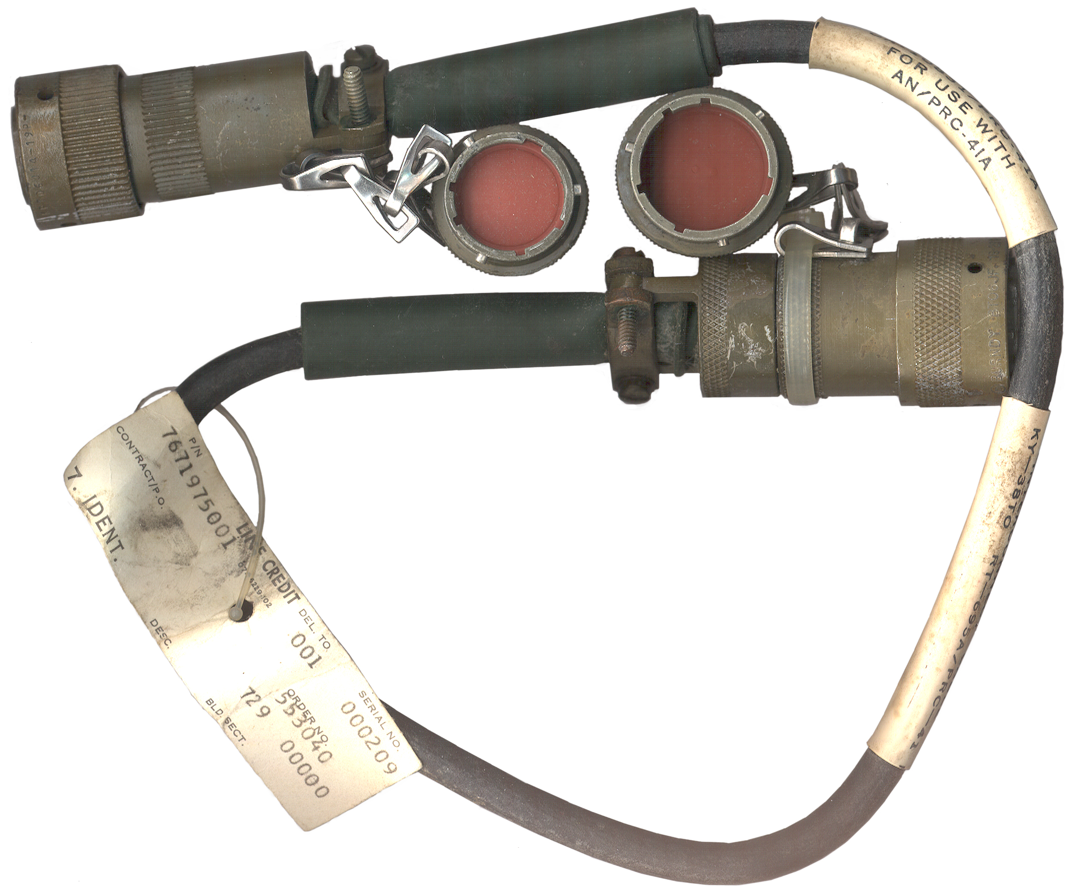
Interconnect Cable KY-38 to RT-695A/PRC-41
CX-10831/PRC-41A for use with AN/PRC-41A
p/n 7671975001 s/n 209 order No. 553040 729 00000
Brundy BT06J F 16-26S - mates to KY-38
ITT Cannon- 6850 KPT06J14-19P - mates to PRC-41
Note that the end plugs have splines that mate with the grooves in the connectors and can NOT rotate! To remove the plug just hold the connector and disconnect the connector like it was mated to a jack.
KY-38 Func
KY-38 Pin
PRC-41 Pin
PRC-41 Func PTT
N
A
PTT
D, E, F, G, c
B
Gnd
Tx ct out ?
Rx pt out ?
U
C
WB or norm audio In ?
U
D
gnd
nc
E
nc
nc
F
nc
G
gnd
D, E, F, G, c
H
gnd
Tx pt audio in
K
J
Norm Audio Out
nc
K
nc
DC In
W
L
+26.5 VDC out
nc
M
nc
Rx ct in
P
N
WB audio Out
D, E, F, G, c
P
gnd
not app
R
H-33-K (CW key)
a
S
Guard out
D, E, F, G, c
T
gnd
U
H-33-J (rem On-Off)
D, E, F, G, c
V
gnd
AUDIO is a GC U-79/U prior generation U-77 type audio connector This is consistent with using an H-33 handset.
AUDIO is a U-229 current audio connector consistent with using an H-138, H-189 or H-250 current style handset.
ZEROIZE is a BNC(f) jack for electrical zeroizing the code key.Controls
There are 4 front panel controls:
RADIO is a three position switch OFF - PLAIN - CIPHER
DELAY is a two position switch IN - OUT (the knob is missing on my KY-38) might be related to turn on time of the radio PTT circuit or turn around time of a satellite link?
VOLUME is a pot 0.........10 (Tx, Rx or both?)
ZEROIZE is a mechanical switch on the key fill door that releases a pin when turned or when the door is opened.
A5 Mechanical Key Holder & A4 (isolated from bus) & A6 Boards (Buss connected)
The Door on the right is for loading the key by means of mechanical programming pins and two spring compression pins inserted into 64 holes and two larger holes. There are about 20 different depths for each pin key. When the door is closed after setting the key with the zeroize knob fully counter clock wise a pin on the back of the zeroize knob presses down another pin sticking up from the key holder.You can first press down the two compression springs then push down each pin and feel the detents. The actual key loader probably loaded the key in parallel with compressing the springs. The key pins have just under an inch of movement (0.98") and have 18 positions, no movement to down 17 steps where each step is about 0.058". After the springs have zeroized the key holder all the key pins are returned to the full up position. In the zeroize position you can only press the key pins down 3 notches, so maybe a good key would not use these positions.
There is a solenoid as part of the key holder mechanism and maybe if the battery power fails the solenoid lets go and the key is lost or maybe the solenoid is only activated from the front panel BNC zeroize connector? The ZEROIZE knob on the key load door holds down a pin when the door is closed and latched. If the knob is turned or the door is opened the key will be lost.
The KY-28 aircraft version has an impact zeroize function in case the plane crashes. The KY-38 key holding mechanical assembly has a weighted lever that is not actuated by anything. If this weight is moved up center the springs are released and the key is zeroized. If the KY-38 was in a vehicle mount then it would take a strong upward blow to zeroize the key holder, like would happen of a jeep ran over a land mine or was parachuted and hit the ground hard.
The chassis construction is the same type as used on the PRC-25 and PRC-77 but the dimensions of the KY-38 are larger. There are a number of machined castings probably for either mechanical ruggedness and/or Tempest shielding. This was an expensive box when new.
A Microswitch at the bottom of the key holder is closed when the springs are compressed (i.e. there is a key loaded).
There are two electrical connections to the key holder.
On the bottom there is a 10 pin plug that mates to a socket wired to the main buss on the bottom of the KY-38 case, has power and ground connections as well as the Microswitch and solenoid firing signals. The Microswitch is closed when a key is loaded and the springs are compressed.
There is a sub assembly that holds the key pin circuitry that has no electrical connection to the 10 pin connector. The printed circuit board (marked ONI24038) with the contacts for the key pins has connections on both sides, one side is marked J1 A & B with contact positions numbered 1 to 55 and the other side is marked J2 A & B with positions numbered 1 to 55. But not all of the positions have traces and not all the traces are connected to anything. A printed circuit board should be installed on both sides of the A4 mechanical key holder.
There are 4 rows of key pins:
Rows 1, 2, 3 and 4 have a common connection through the 17th wire in each of these rows. Why?Row #1 (close to the MOD 4/9 label) maybe a 16x2 or 16x4 matrix
Has a row of 17 wires but only 16 pins
There are only 4 depth contacts active at down 3, 4, 5 or 6, but depth 3 and 6 are the same and depth 4 and 5 are the same. All other depths have no connections.Row #2 just like row #1 maybe a 16 x 2 or 16x4 matrix Row #3, 16 pins maybe a 16 x 14 switch
Has a row of 17 wires but only 16 pins
There are 14 depth contacts active at levels 3 through 15Row #4 maybe a 16 x 15 matrix
Has a row of 17 wires but only 16 pins
There are 15 depth contacts active at levels 2 through 16This appears to be a set of 4 matrix switches that routs the signals. Note that there are 4 electrically isolated matrix switches. To avoid cross connects two pins in the same row should not be at the same depth.
When the zeroize springs are released they lift up two bars that move all the key pins to the top position where there are no contacts (i.e. all open circuits.) There do not appear to be any active contacts at the top and down 3 levels (positions 0, 1 and 2 are all open) maybe as a safety in case the springs did not push the switches all the way up?
The A4 printed circuit board is connected on the side of the A5 key holder closest to the end of the KY-38 and is fastened to it with screws. It does not plug into the buss on the bottom of the KY-38 and probably gets it's positive, negative and ground connection through the PCB on the mechanical pins.
The A6 PCB plugs into the buss at the bottom of the KY-38 case and is also screwed onto the key holder.

Loosen the 4 Black captive Phillips head screws under the key load door
Loosen the 4 captive screws holding the cover onto the front panel and slide the cover off
Loosen the 4 Black captive Phillips head screws (2 near the cover alignment pin and two down near the battery connector)
The chassis now will hinge open and the key load mechanics assembly is now free.
There are two main sub assemblies on the hinged box:The cable connecting the hinged box to the front panel has 13 wires. 5 of these go into the MOD16 box through FL2 through FL6 (tempest filtering) and the remaining 8 wires go into the compartment behind the front panel controls and connectors. 5 of these go through large tempest in line filters.
- The Power supply box has a 13 pin (4, 5, 4) buss inside with 3 plug-in PCBs (A1, A2, and A3). J5 is the plut to the battery box. There are about 5 feedthoughs coming out of the power supply box and going to the cable and/or the 36 pin buss.
- The main buss in the fold out box uses a 36 pin (2x18) socket but only has 17 wires (E1 through E17, R3= E3, R2=E13) connecting it to the rest of the KY-38. This is not a buss where all the sockets has the same traces, but rather an interconnecting buss to connect the various PDBs plugged into it. It's made on a multilayer baord. E8 is ground.
Assembly # Marking Buss Description A1 E-BPX 13 pin Power Supply (PS box) A2 E-PBY/1 13 pin Power Supply (PS box) A3 E-BPZ 13 pin Power supply related (PS box) A4 missing no
connectionKeying PCB A5 MOD 4/9 E-BOR/3 5&6=gnd Mechanical key holder A6 missing 15&16=gnd
19&20=R3Keying PCB A7 missing 15&16=gnd
19&20=R3scrambling? PCB A8 missing 15&16=gnd
19&20=R3scrambling? PCB A9 E-BOO 15&16=gnd
19&20=R329 op amps A10 E-BON 15&16=gnd
19&20=R3Dual 3 kHz LPF A11 MOD 12 E-BOM/3 15&16=gnd
14=R218 op amps A12 MOD 11/13 E-BOL 15&16=gn
13&14=R2dual LPF PCB
#1 cf=18.75 kHz bw= 20 Hz
#2 ?A13 E-BTW/1 7&8=gnd
31&31=R2short PCB A16 MOD 16 Power supply on back of front panel in lid
another PCB in bottom of boxBack side of front panel, under metal cover that has foam stips for PCBs is a small circuit board. Both of the AUDIO connectors are Tempest filtered and have only 4 active wires & ground. The 5 wires going to cable (plus ground) between the front panel and the hinged part has inline tempest filtering. In addition 5 more wires join the cable from inside the MOD16 box. There are 5 wires between the front panel and the small PCB in the MOD 16 box.
The center of the BNC(f) ZEROIZE connector shows up on pin 2 of the A4 connector XA5 and E11 on the main buss PCB. Pins 5 & 6 are ground.
The battery box holds two each BA-4386 or equivalent batteries face to face. They first plug into a center divider that also has the connector to mate with the bottom of the radio and they the center divider with batteries attached slides down into the battery box. You can see the blue connector that mates to the radio on the left side of the center divider. Using two of the same battery type as the PRC-25 also points to its use with the PRC-25.
The bottom of the KY-38 has a 3 pin power connector (J5) A = RB+ and B & C are combined RB- and Chassis ground. The adjacent label says CAUTION Do not exceed 15 VDC. The battery box is missing from this set.
257477BA Battery Adapter
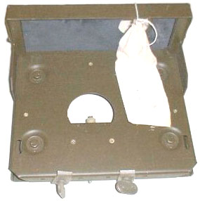
Note that the MT-1029 used with the AM-2060 & PRC-25 or PRC-77 has connectors for the AM-2060 and will not hold the PRC-25 or PRC-77 directly but this mount holds just the radio or a KY-38.
The KY-38 was attached to the MT-3823 shock mount. The KY-38 has indents cast into the front panel like are used on the PRC-25 and PRC-77 for attachment to the AM-2060 amplifier.
FM 24-19 mentions the KY-38
FM 24-12 mentiones use with RT-524, VRC-47
Manual references:
TM 11-5820-401-10-2, VRC-44, VRC-47, VRC-48 & R-442, R-442ADec. 1977.
TM 11-5810-290-14&P
TM 11-5810-300-12 Operator's and Organizational Maintenance Manual, for, NESTOR, Communications Systems, using, TSEC/KY-8 and TSEC/KY-38, with Radio Sets and Associated Equipment. For Official Use Only (FUFO).
Manual References: ST 24-18-2 US Army, Armor Communications Electronics Data, Fort Knox, Kentucky, July 1977
TM 11-5810-224-10 KY-8 & KY-28 Manual
TM 11-5810-245-10 KY-38 26 Aug 1971
TM 11-5810-245-12P KY-38 12 Jul 76 (Ca 13 Jan 78)
TM 11-5810-245-15 KY-38 13 Sep 73
TM 11-5810-245-34 KY-38 17 Sep 73
TM 11-5810-245-34P KY-38 1 Mar 82
TM 11-5810-245-ESC KY-38 18 Dec 73
TM 11-5810-247-10 HYL-3/TSEC Digital Regenerative Repeater
TM 11-5810-209-12P TSEC/KW-7 Teletype
 |
KY-8The KY-8 is a 30 pound unit designed for vehicle mounting. |
|
 |
KY-28The KY-28 is in 2 parts, |
|
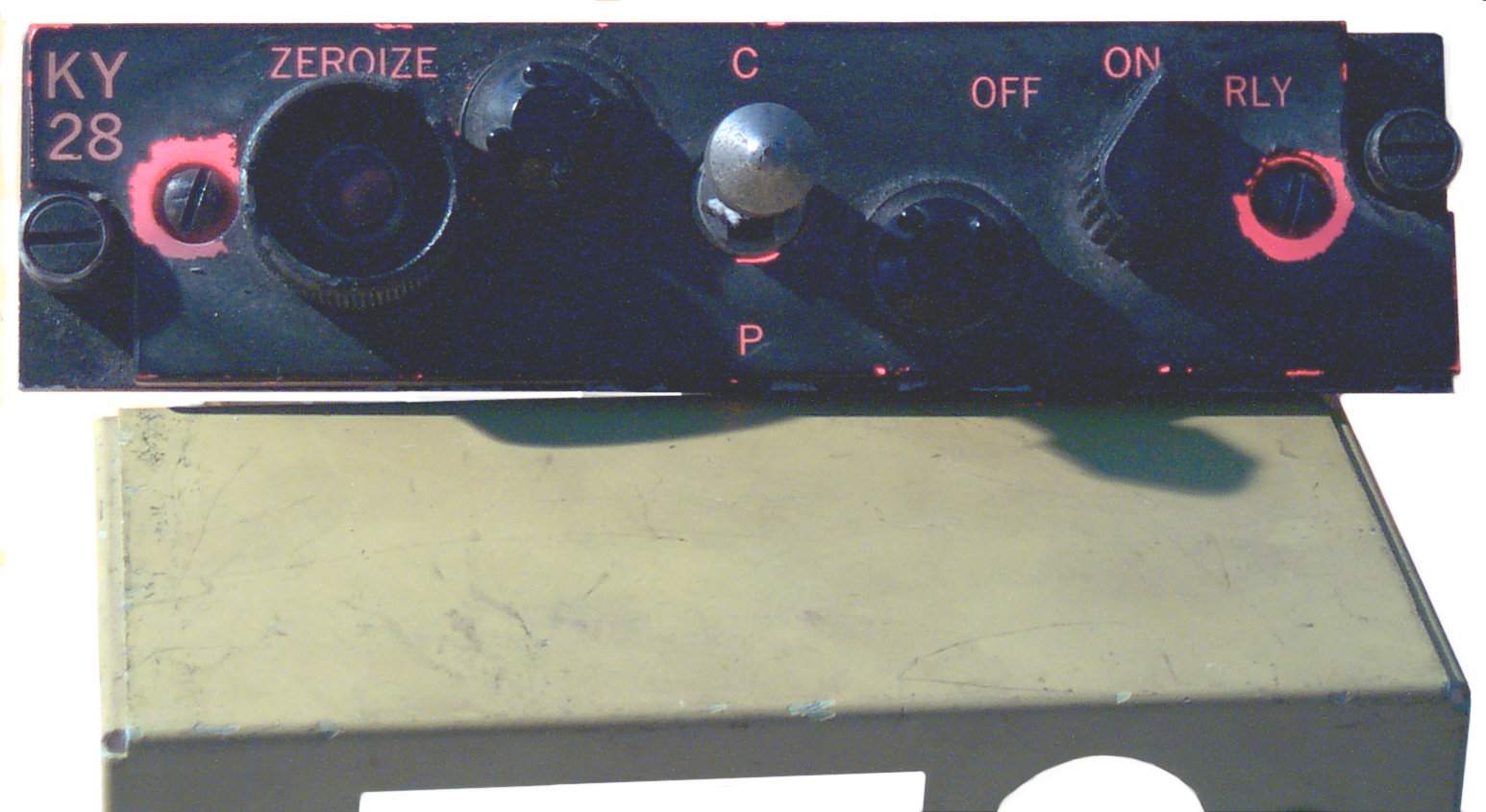 |
C-8057/ARC This an instrument panel
control for the KY-28. It has switches for Zeroize,
Cipher-Plain and OFF-ON-RLY. This control supports
retransmission (Relay) operations using 2 radios. 5.75'
wide, 1.5" high, 3" deep. Like many aircraft instruments the very front of the panel is a sheet of clear plastic painted black with the legends engraved. When the panel lights are turned on they light up the plastic interior, but only the engraved legends glow red because of the red filter that surrounds each lamp bulb. There's a rubber gasket under the head of the lamp holder so that white light does not leak out into the cockpit. On this panel there is also some red glow around the screw holes which have had the black paint worn off. The Cipher-Plain switch is a pull to change type so it will not accidentally change position. The Zeroize push button is a normally open type. When it's pressed the current energizes the solenoid that releases the spring which in turn moves all the key sliders back to their starting position. The connector on the rear is an MS3112E-12-10P This unit was made by CAGE 67116 which was Computronics in 1974. |
 |
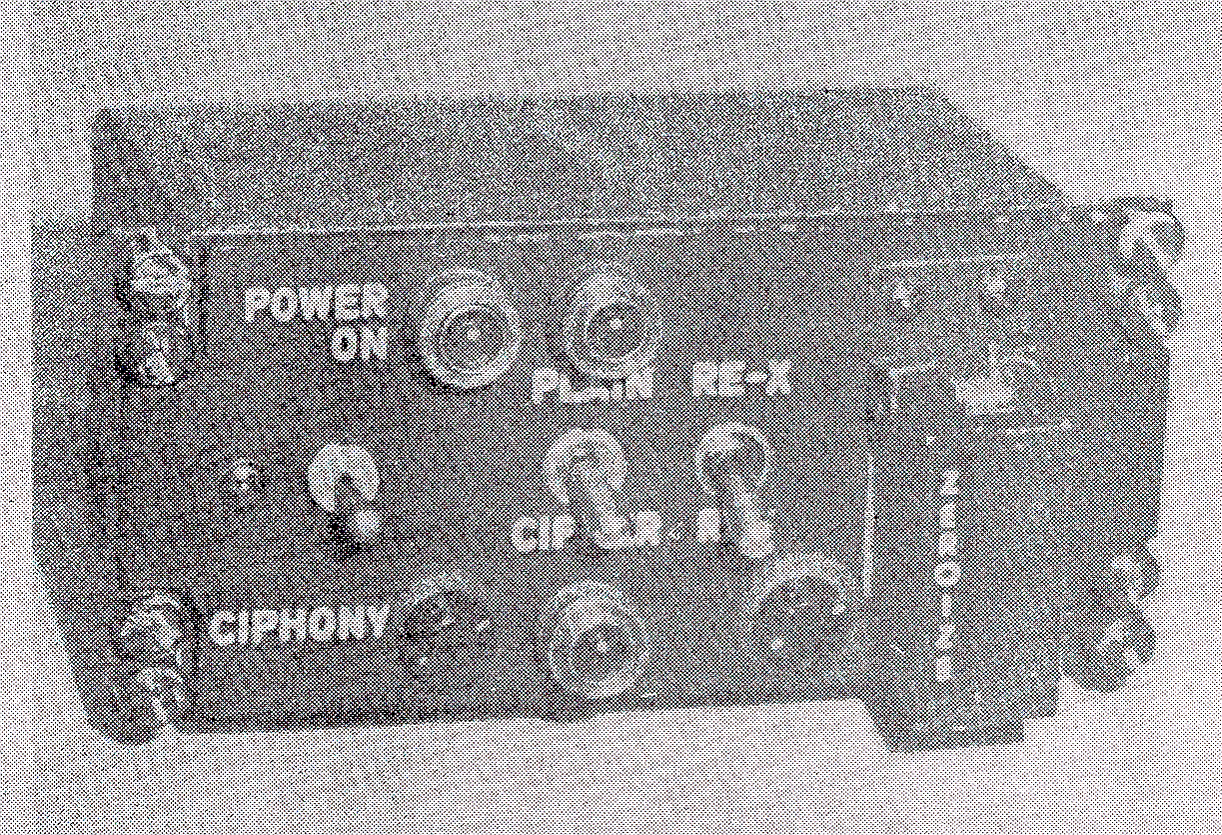
C-8157The three lens are missing for the POWER ON, and PLAIN or CIPHER lamps. If you have some let me know. I've heard the lamp covers are the common twist to dim type and were orange, green and red. Not sure which color to which lamp? You can see roughly what they look like in the black and white photo below. The C-8157 is another instrument panel control for the KY-28. This is a larger control box that includes 3 indicator lamps as well as 4 switches. POWERON/CIPHONY, PLAIN/CIPHER, RE-X/REG or Normal and Zeroize. |
 |
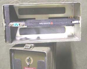
 This photo was
in the same section of ST 24-18-2 US Army, Armor
Communications Electronics Data, Fort Knox, Kentucky, July 1977 as
the other B&W KY-xx series NESTOR photos. I think it is
a KW-7 (Jerry Proc)
used with teletype equipment.
This photo was
in the same section of ST 24-18-2 US Army, Armor
Communications Electronics Data, Fort Knox, Kentucky, July 1977 as
the other B&W KY-xx series NESTOR photos. I think it is
a KW-7 (Jerry Proc)
used with teletype equipment.KYV()-2 Secure Voice Module - digital encryption
Voice Security Patents -
PSM-13 Battery Test Set -
USAF - M151A1 - MRC-108 Combat Forward Air Controller's Communications Jeep by Robin Michael -
ARC-51 can use the KY-38 as well as most tactical radios made after the PRC-25 (the PRC-25B should work with the KY-38).
Body of Secrets by James Bamford, ISBN 0-385-49907-8 mentions the KY-38 as being used in Vietnam and later we tried to recall about 700 of them which were staged in a warehouse at Tan Son Nhut Air Base ready to be shipped back to the U.S. but got left when we evacuated. Keying material for about 12 Months was also left in the warehouse. (pg 352, 353).
Back to Brooke's Crypto, KYV-2 Secure Voice Module, PRC-68, Military Audio, Squad Radio, Military Information, Home page
Page created 26 Nov 2002.