Integrating Sphere
© Brooke Clarke 2019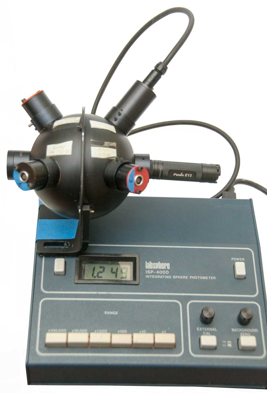 |
|
| YouTube: Integrating Sphere
Testing Flashlight |
4" Sphere
Description
4" Sphere & 1" Ports
Sensors
Port Filters
Cables
Photos
Labsphere ISP-4000
Description
Operation
Photos
LabSphere SC-5000
Description
Metrologic Photometer 45-230
Molectron Pyroelectric Joulemeter Patent
Patents
Related
PVC Integrating Sphere
References
Links
Background
When Edison was working on the electric light he was concerned about the total light output and comparing that to a kerosene lantern or some other light then in use. To do this he used an integrating sphere (Wiki). The idea is that light will bounce around inside the sphere (painted a very reflective white on the inside) and in the process integrate all the light. A sensor is also in the sphere, but there is no direct path from the light source to the sensor. Lumens (Wiki) is the common measure for light. The light actually falling on a subject is measured in Lux (Wiki) where a Lux is 1 Lumen per square meter. Lux varies from 0.0001 (overcast night sky) to 100,000 Direct Sunlight. Also see Star Magnitude. A prior unit for measuring the light falling on a surface was the Candlepower (Wiki).
Flashlights are commonly rated based on their total Lumen output. But that does not tell you much since that light may be spread over a hemisphere like from a camping lantern or focused into a sharp beam.
I started this web page because I want to measure the light output from a bunch of flashlights that all use a AA battery, so hopefully this 4" sphere will work.
Sphere Description
A sphere may be made in two parts that are bolted together using a flange. That allows coating the inside surface with something very white.
They also have a number of "ports" so that light can enter the sphere, for various types of photo sensors and maybe one or more standard light sources for calibration.
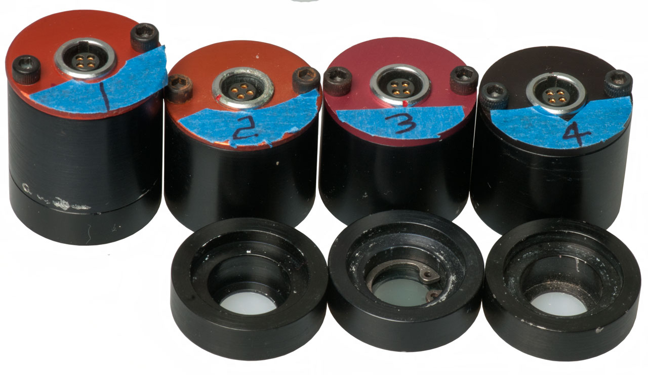
4" Sphere
Each hemisphere has 3 ports. One at the top center and two additional ports down 45 degrees and these are seperated by 90 degrees. One of the top ports is empty (input?) the opposite top port is plugged.
The other 4 ports have some type of electro optical gadget installed with a 4 socket connector.
Hand written labels on Sphere ports:
Yellow Temporal
Yellow Avg. Power
Green Temporal
Green Avg. Power
Port pinch hex set screws are 4-40 thread and 0.050" hex wrench.
Sensors
Maybe Silicon Detector Assemblies: SDA-50-U
Detectors web page - Datasheet - mentions 1.2" standard port, so newer than this integrating sphere.
The Hamamatsu S2281 190 to 1100 nm Reference Si photodiode is packaged in a metal disk that's 25.0 +/-0.1mm diameter. It has an active circular window 11.1mm dia (7/16" dia). and has a BNCf connector anode ground. This would fit the port and would allow calibrated measurements.
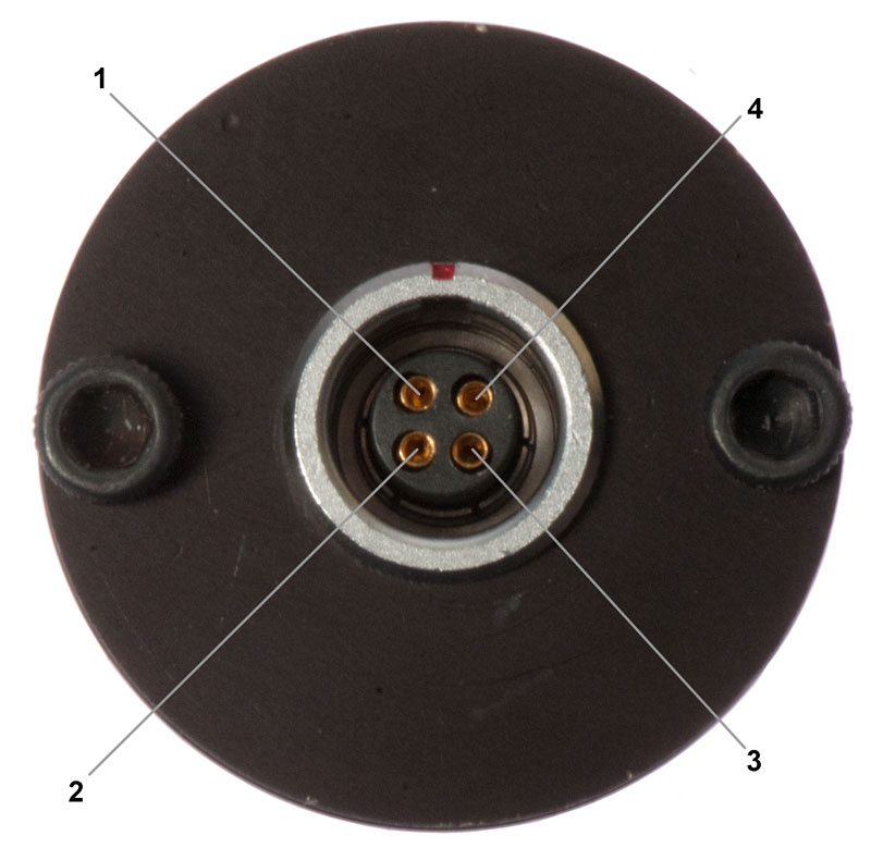
Black Connector Plate
Body diameter is 0.990".
Allen screws on connector plate: 3/32"
The ports on the integrating sphere have a lip to prevent the sensor from falling inside (see Fig 1 and Fig 2) where the hole in the lip is 0.750" dia.
Lemo connector. mating shell may be FGG.0B.304.CLAD52.
00 multipole B
Insert configuration: 304
Series: 0B-0K-0T
See Fig 4 below.
the LEMO connector in the sensor is a EG (0, O, C, G, Q) ??B
the sensor PCB is p/n 87-1062-14 Rev A.
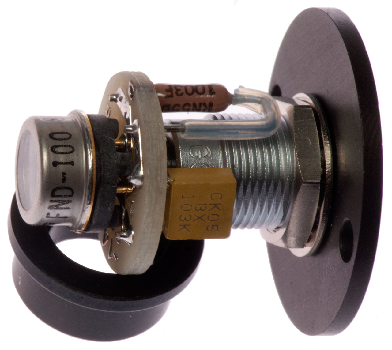
EG&G FND-100
Thor Labs photodiode overview (but not the FND-100).
Hamamatsu Silicon Photodiodes.pdf
The TO-5 package (Wiki) body 5/16" dia (the flange has been ground down eliminating the tab. This package supports between 2 and 10 leads.
The TO-5 to 3/4" gap filler part is black metal.
3 leads: Anode, Cathode & Case.
5.1 sq mm area.
100 V reverse bias typical.
1% linearity over 7 decades
400 to 1150 nm spectral response, peaks around 900 nm.
Sensor Wiring
Lemo
Cable
MS3116F8-3P
BNC
1
White
A
2 & 3
Black &
coax-shieldB Shield 4
coax-center
Center
The voltage output on pins 1 and 4 is near zero when it's dark and goes up to hundreds of mV with bright light (EA4 Flashlight 860 Lumens).
The BNC and MS connectors seem to have the same signal, so maybe for different photometer models?
The SC-5000 has BNC inputs.
There is a capacitor (CK05BX 103K 0.01uF) and a resistor (1003F 100k) in addition to the EG&G FND-100 with date code 8814A (1988 week 14)
Pin 1: to 100k resistor then to Terminal X of FND-100. The 0.01uF cap is between terminal X and ground (pins 2 & 3) = white wire
Pins 2 & 3 to body of FND-100. =coax shield & black wire
Pin 4: to terminal Y on FND-100 = coax center conductor
Orange Connector Plate
EG&G SGD-100A
Has 1003F with CK05BX 103K CAP AND 511K resistor with CK05BX 223K capacitor.
The TO-5 to 3/4" gap filler part is white plastic.
This sensor has a very dense neutral density filter fitted that does not want to come off.
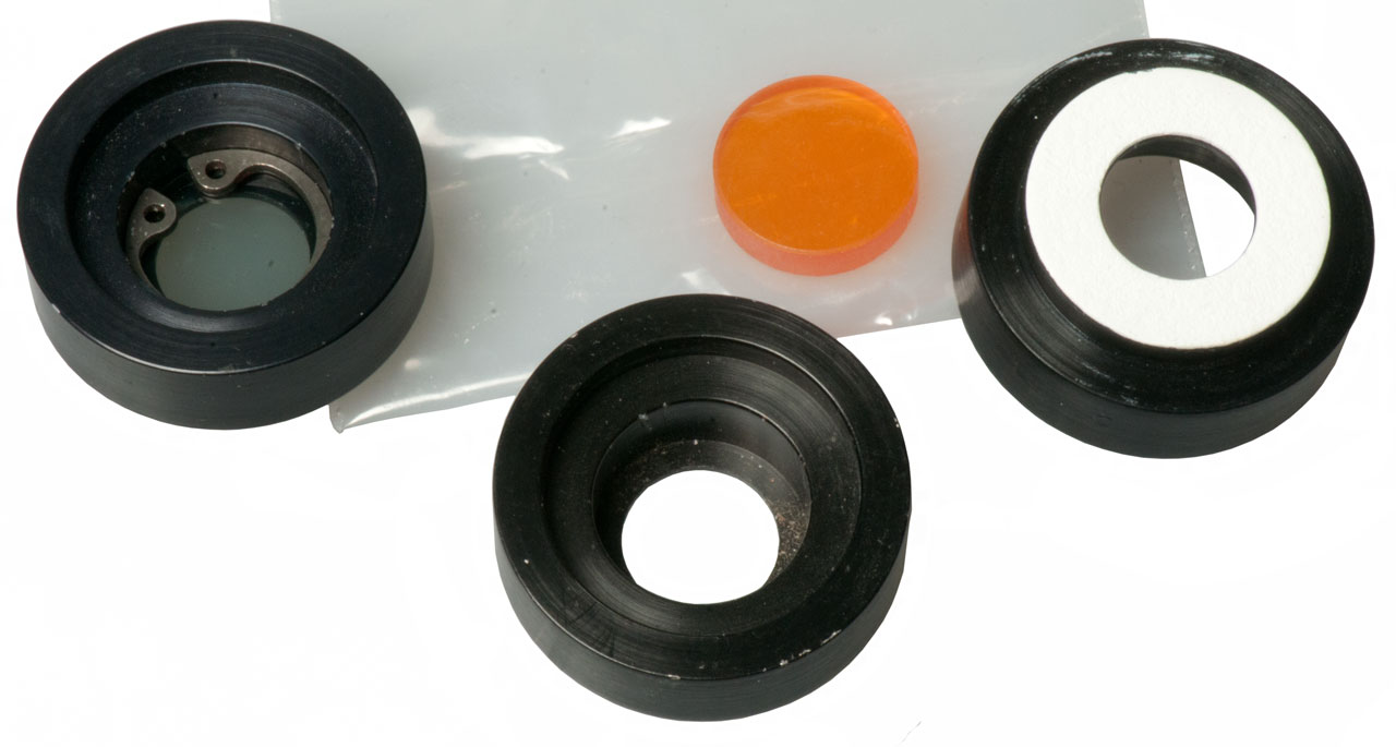
Pink Connector Plate
EG&G SGD-100A
The TO-5 to 3/4" gap filler part is white plastic.
2 resistors & 2 caps - maybe different wiring?
In the bag with this sensor was an Orange (UV?) filter 0.500" dia x 0.120" thk
5.1 sq mm area
400 to 1150 nm resposnse
0 to 180 Volts
3 leads: Anode, Cathode & Case
4 pF (100V) compared to 8.5 pF (90V) for the FND-100 so faster.
Sensor Output
Sensor numbering as shown in Fig 11 below. Measured with FLuke 87 V DMM on mVDC range.
Black (-) & White (+)
Coax shield (-), Center (+)
#
Room
860
Lumens
Room
860
Lumens
1
5
186
-0.5
-50
2
203
511
-19.2
-36
3
177
513
-35.1
-39
4
-0.1
0.2
-0.2
-36*
* Jumps to -39 (80 L) then drifts back to -0.2
No. 4 seems to be dead. That may account for thinking there was a cable problem.
No. 1 has a dense filter installed hence the lower readings for room and bright light.
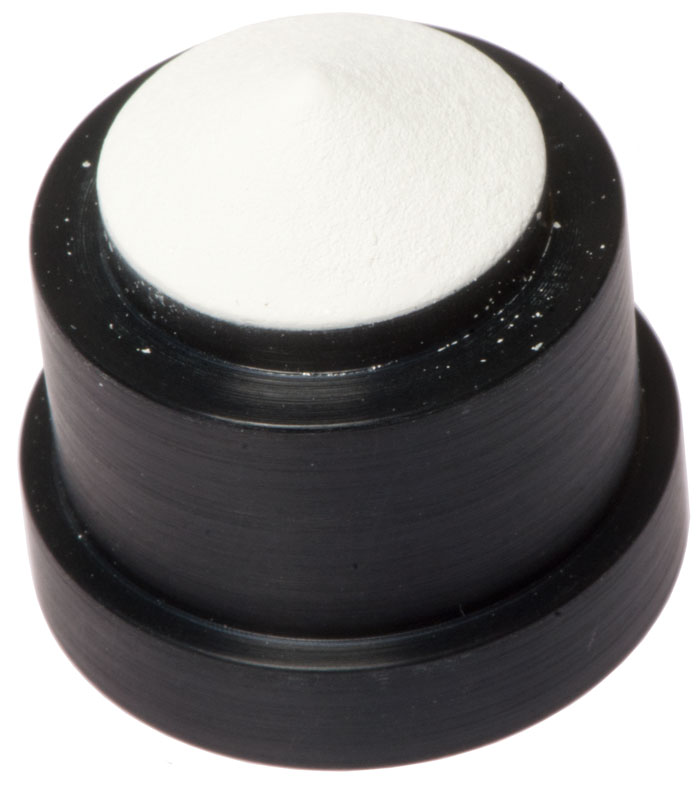
Port Filters
These fit between the sensor and the 3/4" hole at the bottom of the port. They have a 3/4" male nose and a 3/4" female tail that accepts the nose of the sensor.
That means you can stack them. The tip of the nose is white. There is no groove for a snap ring. The snap ring is a friction fit inside the 1/2" filter cavity.
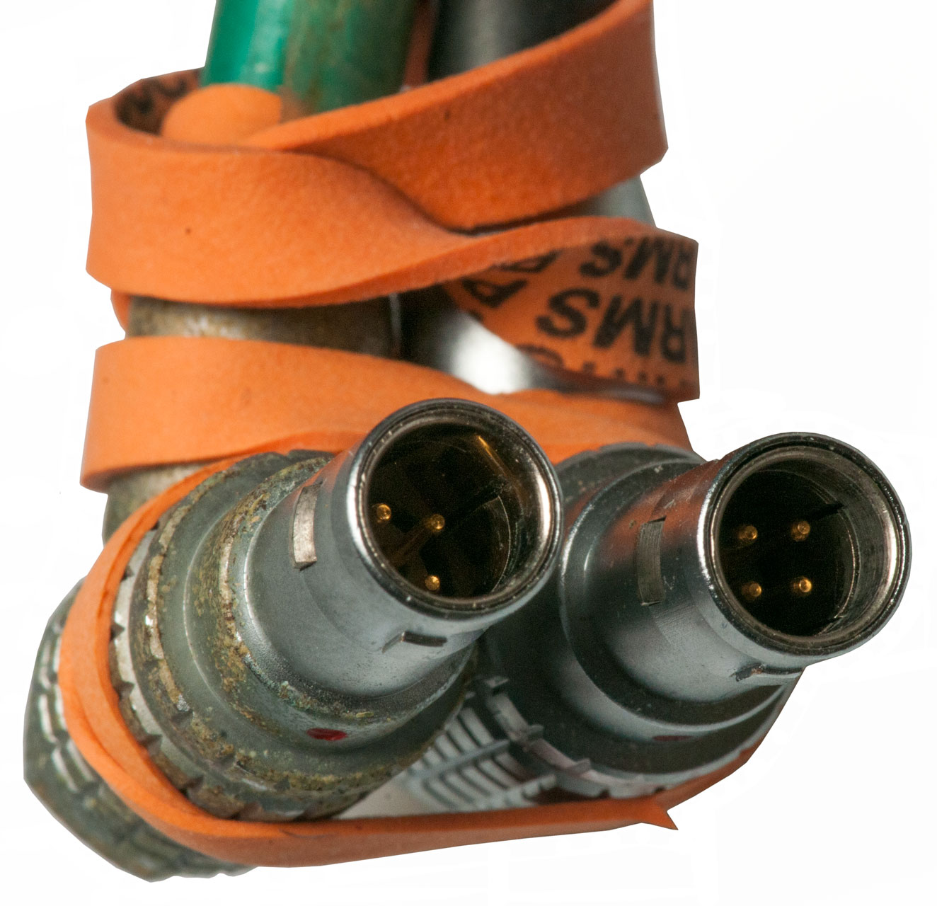
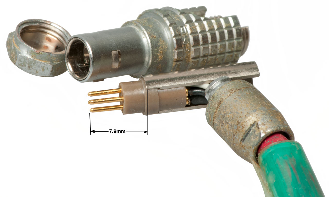
Cables
Both cables have electrical problems.Sensor 4-pin connector marked: LEMO FHG 0B. See Fig 10.
The cable with wire ends has the male pins inside the LEMO connector set way too far back, i.e. they are not plugging into the sensor. Not the case, just different male pin lengths.
The cable with BNC and MS connectors has opens or shorts. Need to test . . . The bare wire end cable works fine. More LEMO connectors on order (FGG 0B).
Sphere Photos


Labsphere ISP-4000
Description
I'm guessing this was made to work with 1" ports since the sensor is 1" in diameter. I expect the nose to be 3/4", waiting for it to get here.
ISP: Integrating Sphere Photometer
Sensor
Sensor Cable
The connectors are Smiths Interconnect "D Series".
The sensor connector is a DO1 with 3 contacts and the ISP-4000 connector is a DO2 with 7 contacts.
Pinouts TBD. Maybe the ISP uses different pins for different types of sensors?
Operation
This is an analog instrument that has a digital 2000 count LCD display. There is no provision for remote control like on the SC-5000.
Front Panel
Push On/Push Off Buttons: Power, Backlight, External Cal, Background Zero, Range: x100,000; x10,000; x1,000; x100; x10; x1
10 Turn Knobs: External Cal and Background Zero.
Digital display range is from 0.001 to 1.999. So the minimum reading is 0.001 and the maximum reading is 1,999,999. That's 9 orders of magnitude! Do not know what units.
As received when the Background Zero is turned off the meter reads 0.001 which is pretty good. On the main PCB there are a couple of pots near the analog input one of which I'm guessing is an op amp zero, the other for scale factor.When the Fenix E12 is inserted and turned to full brightness with a fresh L91 battery and the External Cal is turned on it's possible to adjust so that the display reads 1.30 on the x100 range, i.e. 130 Lumens. But it's a delicate setting. When x1,000 is pressed the display changes to 0.130. This suggests that the readings should be made with both Cal and Zero turned off and the meter read then an external multiplication used to get to Lumens. This way at a future time you could repeat readings that could not be repeated if either Cal or Zero were in use and a knob was bumped.
If the E12 flashlight is moved up - down - left - right the reading changes between 129 and 142 or about =/- 5%.
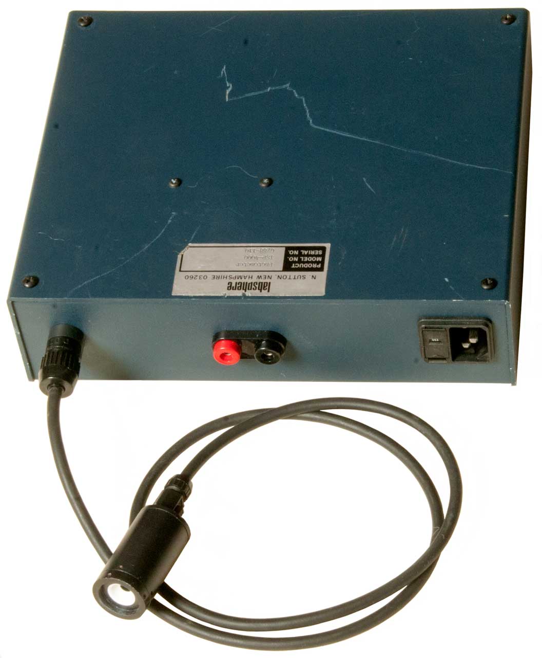
Back Panel
The Red and Black Banana Jacks are an analog output, but it is linked to the external Cal On/Off and the range switch in a way that I haven't yet figured out.
Photos
Fig 1 The new Fedex box label misspells my name
and the starting label has it correct.
This caused a 5 day delay in receiving the box.
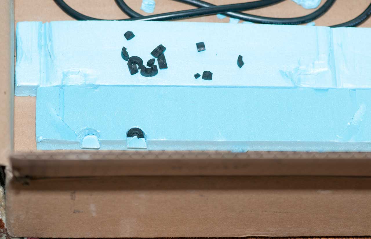
Fig 1 Box
The stiff foam and/or the loose batteries caused
all the plastic feet to be destroyed. That's why
the 4 corner bottom screws were loose.
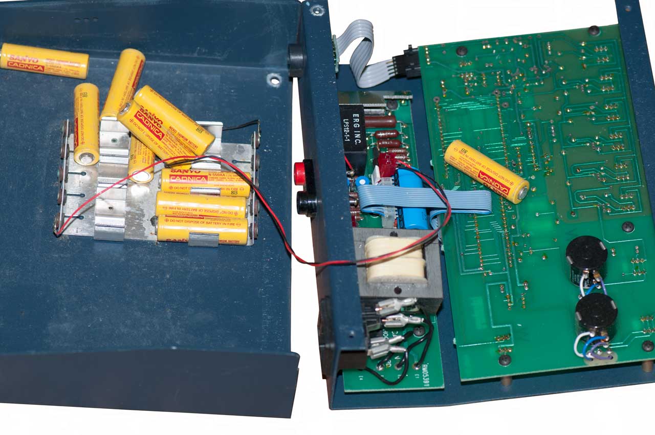
Fig 2 A look inside to see what's
causing the noise. Loose AA Ni-Cad cells.
Fig 3 the included sensor fits the 1" ports.
Fig 4 Red & Black Banana Jacks function: TBD
Guess recorder output
Fig 5 Working with Fenix E12. Light leaking out of crack.


Labsphere SC-5000 Integrating Sphere
System Control
Description
SC: Sphere Controller
This appears to be a general purpose light meter and maybe a power supply or switch for calibration light sources. There are 3 input channels for:
- Silicon or Germanium diode in current mode (See: Weston 594)
- Thermopile (Wiki) or Lead-Sulfide or PMT (See: Eppley Pyranometers, Battery Heat)
- Lead-Sulfide with 84 Volts Bias. (when used as photoresistor (Wiki: Lead sulfide (PbS) and indium antimonide (InSb) LDRs (light-dependent resistors) are used for the mid-infrared spectral region.)
Front Panel
Power Push On/Off & LED
LCD Guessing 2x40 characters
Buttons: Functions: Cal & Options, Data Adjust: Zero & Norm, Range: Up, Down, Auto
Talk, Listen & Remote LEDs
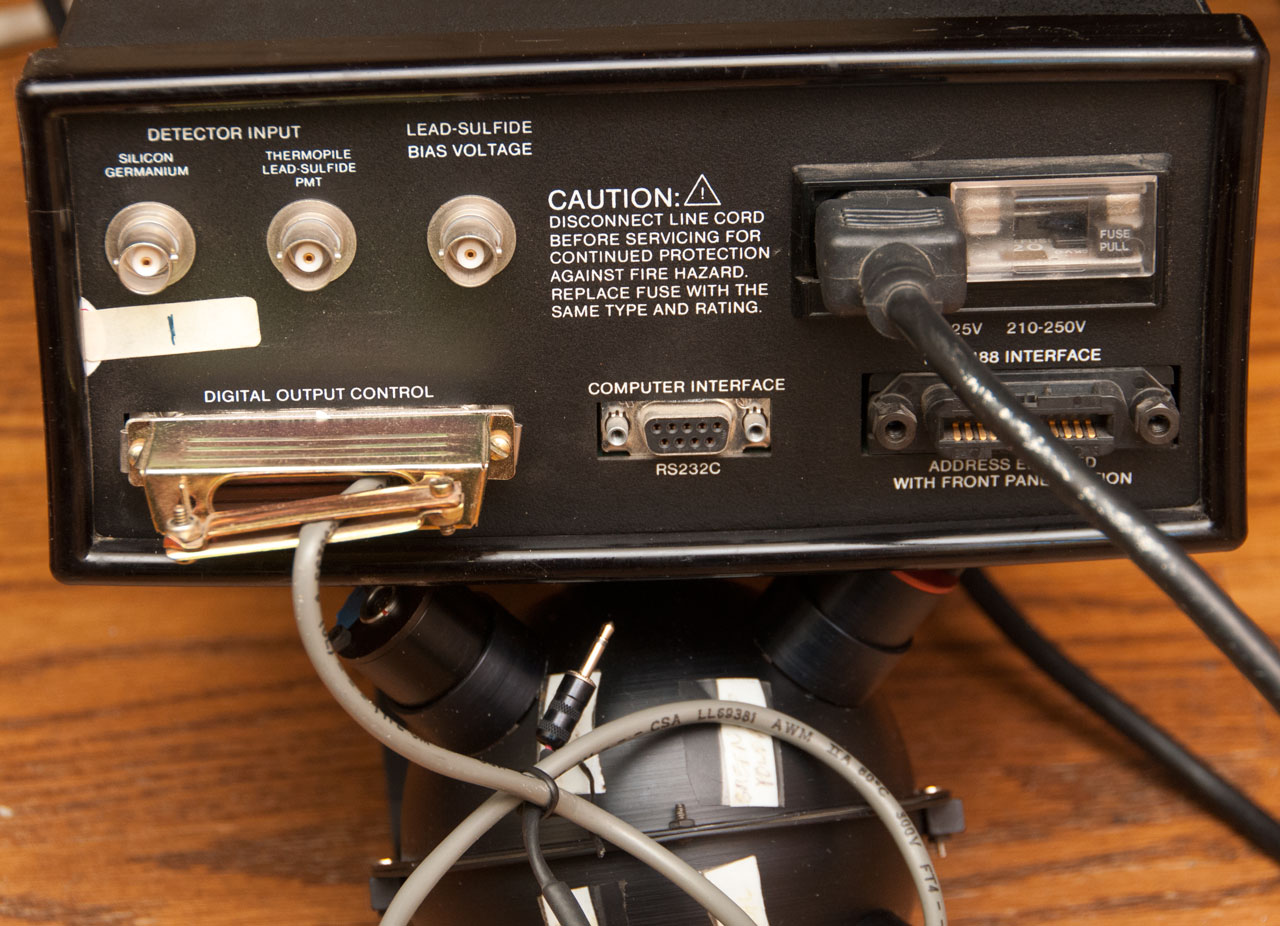
Fear Panel
Has three BNC jacks. They have floating shields. i.e. each shield is independent of the other shields and chassis ground.
Channel 1
Silicon or Germanium diodes operated in photovoltaic mode (i.e. diode generates voltage/current) best measured as current into a virtual short. Diode- to center pin.
5 relays
Channel 2
Thermopile, Lead-Sulfate, PMT;
One Relay
Channel 3
Lead-Sulfide Bias Voltage (84 VDC bias, + on center conductor.)
No relay.
Digital Output Control
Now only single bit output to a 3/32" (2.4mm) plug
Remote Control
RS-232 Remote control DB-9
IEEE-488 Remote Control.
Operation
There are 3 BNC-f inputs on the back panel but there does not seem to be any way to select which is used on the front panel. Guessing that only one of the three can be used at any one time so no need to select.
It is not clear what types of sensor and how it is wired to the SC-5000. Also what bias mode is used for the Silicon diode.
If you know about operation or have a manual please let me know.
Coax cable center: red coax in center
Black cable: black coax input shield
display shows current that varies with input (Cal1: Amps mode).
+0.124E-5 Amps room light
+0.605E-3 Terralux 100 flashlight
Fig 1 Front
Fig 2 Back
Fig 3 Inside Top
Power Supply upper center
Analog input- digital output lower right
Note three different channels of input.
Digital & front panel on left.
Fig 4 Hamamatsu S280 Photodiode
Red dot = Red post = Center of BNC = working in Amps mode


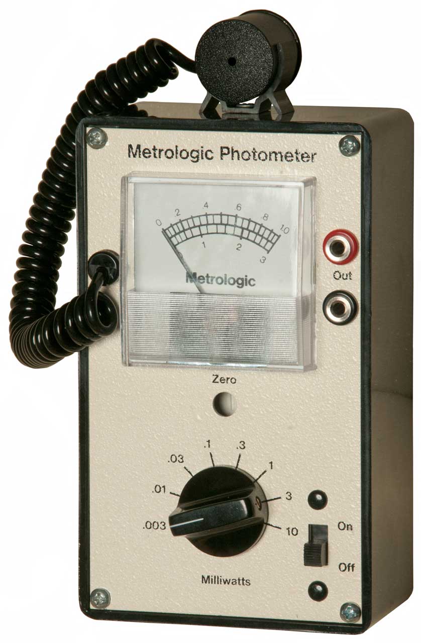
Metrologic Photometer 45-230
Wiki: Photometer - Radiometry -
Web.archive of UoA: Radiometry and photometry FAQ -
Got this because:
1. the sensor is 1" diameter and so should fit this integrating sphere, and
2. the meter is calibrated in mW not light units, so may be a power meter rather than a light meter, ie responds to IR and/or UV?
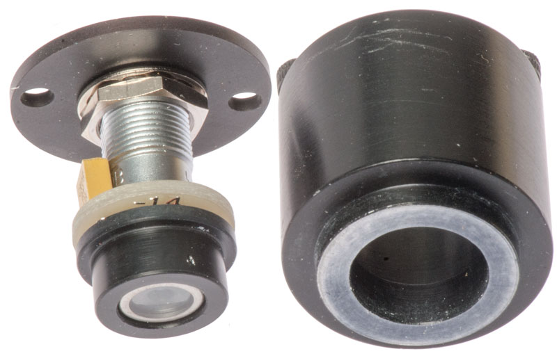
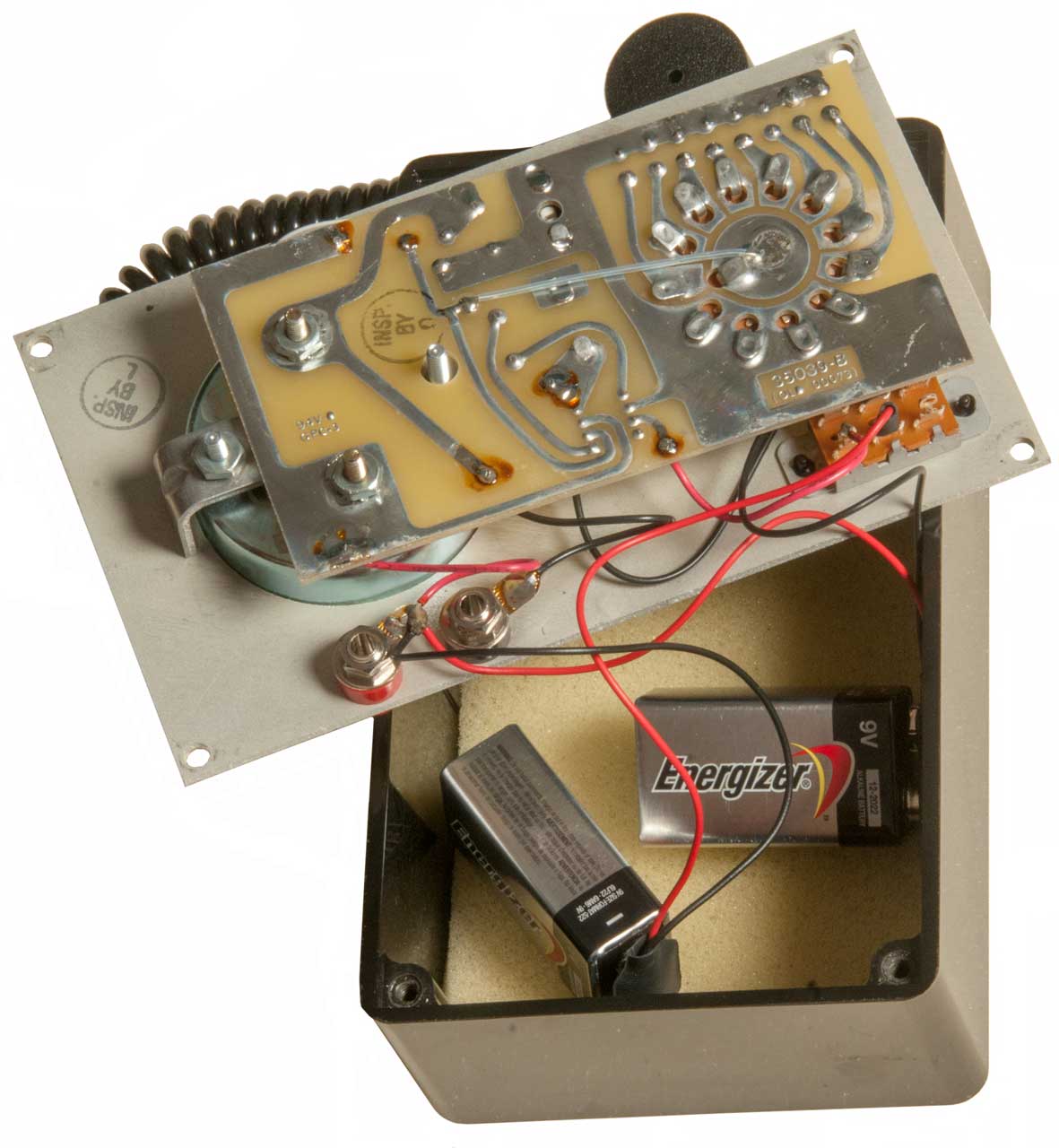
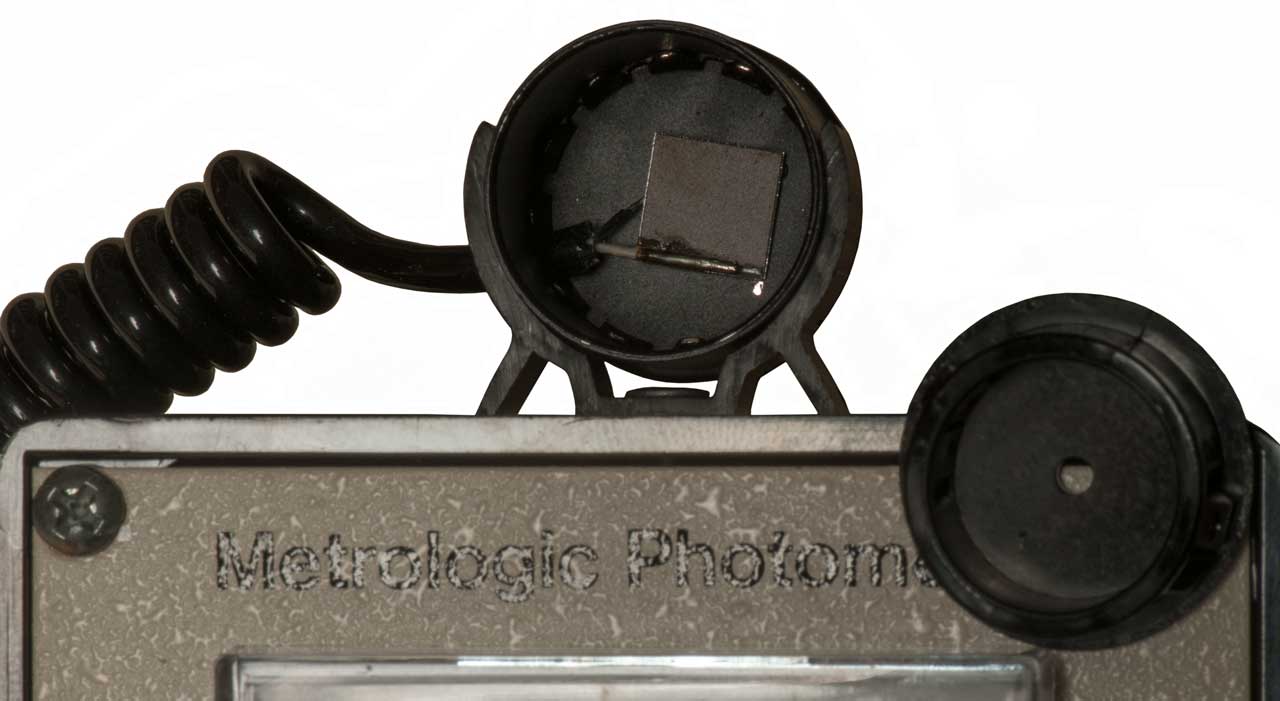
Needs two each 9V batteries. It's not at all clear what type of sensor is used. The sensor is pretty much a plastic cup that's mostly empty. There's a front black plastic cap with a small hole. Removing the cap greatly increases the sensitivity. Maybe should be called a Radiometer (Wiki) since light units are not being used.
PS When working with a Mintron Low Light TV camera I found installing the black plastic cap did not block IR light and so aluminum foil needed to be added to the cap to get a black flat exposure. So if this is a very sensitive power meter that responds to IR it may have a similar problem.
Range switch marked: 0.003, 0.01, 0.03, 0.1, 0.3, 1, 3, 10. The range switch does not stop but rotates through the 4 unmarked positions.
The sensor is a raw 10 x 10 mm chip with no glass, i.e. maybe sensitive to IR and UV.
Based on NBS 300 Vol 7 (References): If the sensor is Lead Sulfide (Wiki: PbS) then at room temperature it's sensitive in the near IR aka Short Wave IR (SWIR) range of 1 to 2.5 um. This can be tested using some IR flashlights.
I used one of the Streamlight Sidewinder flashlights to shine Red, Blue and IR light into the sensor, and it had a strong response to the blue light and weak responce to the IR light, so probably not PbS.
Photos
Fig 1 Sensor body is 1.000" OD.
Fig 2 Batteries
Fig 3 Sensor Felt washer (9mm ID) removed.
Chip is about 10 mm square.
Hole in cap is 0.10" ID.
Molectron Pyuroelectric Joulemeter Patent
4963741 Large area pyroelectric joulemete, John C. McMullin, Molectron Detector Inc, 1990-10-16 - 23 patent citations, "Typical pyroelectric materials known in the art are lithium niobate (Wiki), barium strontium niobate (Wiki), lithium tantalate (Wiki), lead zirconate titanate (Wiki: PZT). lantham-doped lead zirconate titanate , thalium arsenic selenide, and polyvinylidene fluoride (Wiki: PVDF)."
Patents
Did not find any patents for the integrating sphere itself, only patents that use one to accomplish some task.
Related
Fire
Flashlights
Hilger & Watts Spectrometer D 186.3/290
Lights
Light Meters
Optical Spectrum Analyzers
Optics
PVC Integrating Sphere
YouTube:How to measure Flashlight Lumens and Candela using ANSI/NEMA FL1 standards - YouTube: DIY Lumen Measuring Device. Integrating Shpere, and Lumen Tube - Styrofoam picnic box, (10:09) Lumen Tube (PVC) - reminder about temperature. -
Internet Lumens vs Actual Lumens -
Forums
Budget Light Forum (BLF) - Texas_Ace integrating PVC sphere with no math involved -
Candle Power Forums - Estimate Lux & Lumens with Light Meter? LumenToob -
Reviews
Johnny Mac Reviews -
Advanced Knife Bro - Flashlights -Moonlight and Firefly Modes on Flashlights. What those about? -
2018 May discovered a YouTube on making your own.
Internet Lumens vs Actual Lumens, and the 100 watt LED test -
DIY Lumen Measuring Device. Integrating Shpere, and Lumen Tube.
How to measure Flashlight Lumens and Candela using ANSI/NEMA FL1 standards
References
Edmund Optics - General Purpose Integrating Spheres - 2", 4" (has 1" ports) & 6" - Accessories -
Gamma-Sci - Integrating Spheres
Instrument Systems - Integrating Spheres - 3", 6", 12" and larger
LabSphere - Integrating Sphere Theory & Design.pdf - Integrating Spheres - The Light Measuring spheres range for 1.4 to 2 meters ID. The Reflectance/Transmittance spheres are all 6" ID with a larger than normal port for the sample. General Purpose includes a number of 4" ID spheres. These come with either 3 or 4 ports located in different places.
Light-Measurement - Tutorials On Light Measurement.pdf - III.1.a Integrating Sphere
Newport - Integrating Sphere Fundamentals and Applications - Port plugs come in sizes: 1/2", 1", 1-1/2", 2,5"
SPIE - Field Guide to Illumination - Integrating Sphere -
NBS Pub 300 Vol 7: Precision Measurement and Calibration, Radiometry and Photometry, Nov. 1971 - 695 pages.
Ch 8 Theory, Construction, and use of the Photometric Integrating Sphere Rosa & Taylor, 1921Wiki: Electro-Optics, Photonics, Photodetectors, Photoelectric Effect, Photovoltaic effect (selenium), Photodiode, Solar Cell (the short circuit current is proportional to the light intensity), Stoletov's law,
DeCusatis, C., "Handbook of Applied Photometry." AIP Press (1997). Authoritative, with pertinent chapters written by technical experts at BIPM, CIE and NIST. Skip chapter 4! (test at left from Radiometry and photometry FAQ book on order 5/7/2019
Links
PRC68, Alphanumeric Index of Web pages, Contact, Products for Sale
Page Created 2019 April 10