 |
 |
|
|
Some time prior to the Feb 2023 snow the
top of the OE-254 feed cone broke off.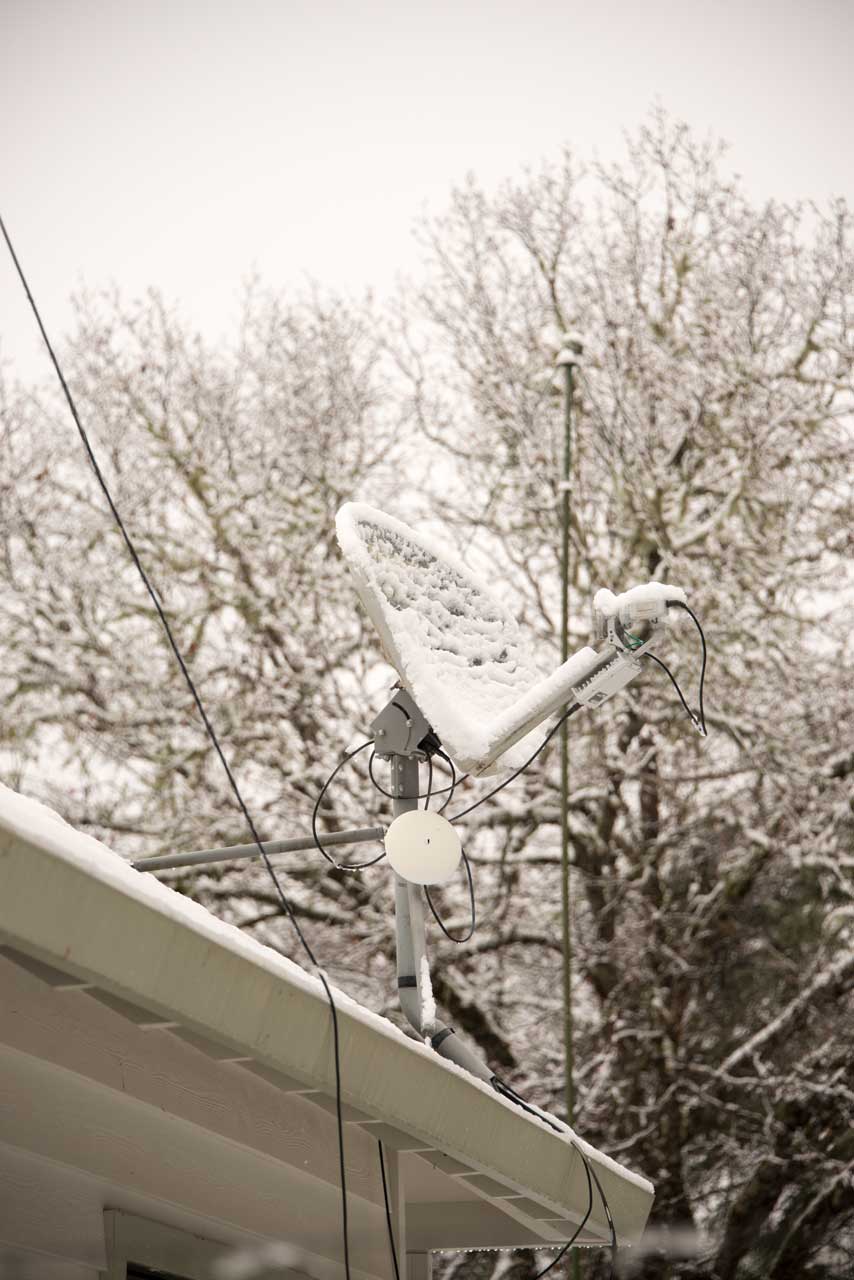 |
|
|
|
|
| Some time prior to the Feb 2023 snow the
top of the OE-254 feed cone broke off. |
Prior to the OE-254 biconical antenna (Wiki) there was the RC-292 1/4 Wave vertical. This worked fine for radios like the PRC-8, PRC-9 & PRC-10, PRC-25, PRC-77, and the VHF Low band radios in the PRC-68 Family, the VRC-12 family, he RT-246 & many more. This works fine over some narrow band of frequencies by assembling the elements to be the correct length for the chosen frequency band.
But with the advent of frequency hopping radios, like the SINCGARS, RT-1439 & RT-1523 and more modern versions there is need for a wide band antenna that requires no tuning or element selection to cover the full VHF Low Band.
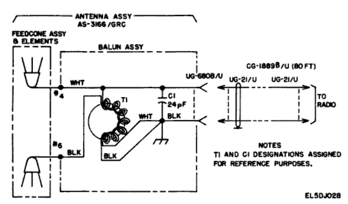
The OE-254/GRC is a biconical antenna that uses a Balun (BALanced to UNbalanced transformer) to match the 50 Ohm coax line and radio to the 200 Ohm antenna. It covers the 30 to 88 MHz frequency range without any element adjustments and therefore is said to have an instantaneous bandwidth.The RC-292 antenna needs to have three different element lengths to cover the 30 to 88 MHz frequency range and therefore is not suitable for use with frequency hopping radios.The OE-254 was designed for frequency hopping and conventional radios. You also do not need to be lowering and raising the antenna to work anywhere in the 30 to 88 MHz band.I suspect that this bi-conical has a much wider bandwidth than the specification, just as a diskcone antenna (Wiki) has a wide bandwidth.
Note that the AS-1729 and AS-3900 VHF Low band vehicular antennas have about MINUS 6 dB gain relative to a dipole. These would not be suitable for use with the squad radios 1 Watt output power.
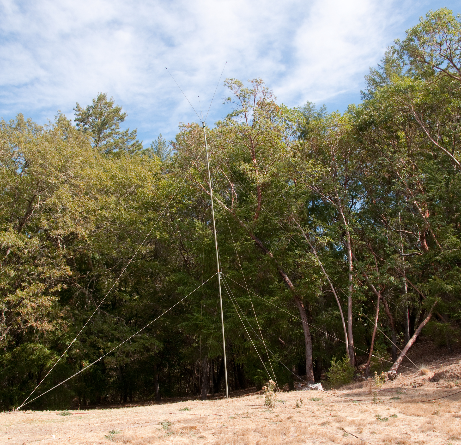
Antenna elevation is very important in this frequency band. Placing the OE-254 on all the mast sections makes a huge difference in it's coverage area. There are some web references to a new wide band antenna that's compact and light weight and is deployed on the ground, i.e. it does not use a mast. This no matter how well matched this antenna is, it never will have the coverage of the OE-254 up on a mast.
These antennas don't seem to be current as of 2008. The Harris RF-9072 Low-Band VHF Discone Antenna may be a replacement.
The Create Discone may also be a replacement.
1.1 Photos
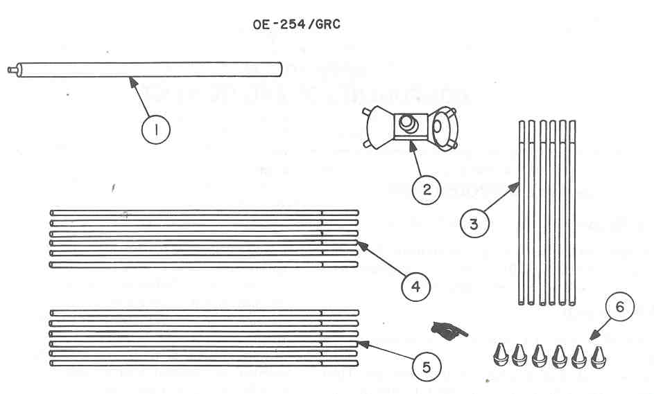
Mast Sections - (Fair Radio photo) look like they have tabs and notches
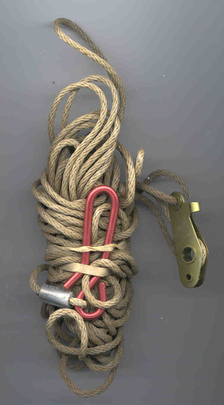
Base Stake, guy stakes, guy ropes, etc. -(Fair Radio photo)
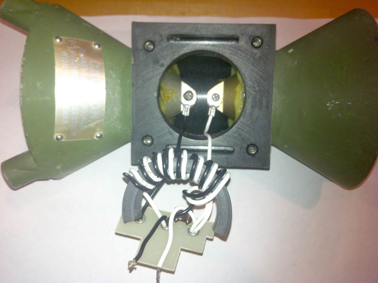
Feedcone Assembly - Red Label: "CAUTION Always use the 30 Inch Insulating Mast Section With This Antenna" The thread in the bottom cone is a little different from the thread used on a broom handle, but it's close. The feedcone consists of a 50 Ohm to 200 Ohm balun transformer driving the upper cone that's all metal and the lower cone that's all metal 180 degrees out of phase with each other. The DC resistance between all the parts is less than 0.1 Ohms. Even with a 4-wire Kelvin Ohm meter I could not see the balun windings. This is probably because the wire used on the balun is big enough to handle 350 Watts of RF power and has a very low DC resistance.
CG-1889C/U Coax Cable Assembly -
Antenna installed on the Lower mast sections (1/2 normal height) -
There are 3 antennas in this photo including the OE-254
- See PRC-126/OF-185 Drive Testing for more info
18 March 2001 -
OE-254 using all the mast sections
(twice as high as before)
2022 it's still up. The guy ropes are not degraded by Sun.
1.2 Problems
All of these problems have solutions and are no reason to not use this antenna. All antennas have similar, if the the exact same, problems that need to be addressed.Safety
The original version must have just used the AB-24 Mast Sections with no end tip and people died and/or were blinded by being impaled. The teardrop shaped tips that are now on the tips of all military antennas are not there to increase the reception of distant stations, but are purely a safety measure.Staking in Soft Ground
If the antenna is erected on soft ground (or sand) the strength of the stakes may not be enough to hold the antenna up when the wind blows. To improve the strength of the staking use two stakes for each guy rope for a total of 16 stakes. This requires adding a pair of stakes at 45 degree intervals rather than only at 90 degree intervals around the mast. The manual shows 4 stakes holding 2 guy ropes each for hard ground.Feedcone Separation
The upper and lower cones are Aluminum castings that are glued to a center insulator. It's possible for the glued joint to crack. See the PS magazine articles for instructions on using cord (NOT WIRE) to tie the cones together. I have an idea how to really fix this problem, but need to try it out.Strain Relief Failure
The Strain Clamp PF-211/G may have too smooth an inner surface and let the coax cable slip. If this happens the coax probably will break free of the connector and the electrical performance will be ruined. The manual and the PS magazine articles recommend using electrical tape to attach the coax to the mast. And to rough up the inner surface of the Clamp.Corrosion
Wherever there is an electrical connection between the cones and between antenna elements there is the possibility of corrosion. In the feedcone that I just received there is corrosion in the element sockets. These need to be cleaned with a small arms cleaning brush and I need to find an anticorrosion compound at my local hardware store.My antenna was put up without any preventive measures and after a couple of months the antenna elements had locked to each other. Large pliers would not undue the joints. The cause was the copper oxidizing. Compare a polished and corroded MS-117A end. You can see that both Silicon Grease and COAX-SEAL are needed at every joint. The reason for adding the COAX-SEAL is that water is the universal solvent. Given time and weather I am concerned that the Silicon Grease is not enough.
Weatherproofing
The manual shows in Figure 2-18, using electrical tape to weatherproof the joint between the coax cable and the feedcone. There are two problems with this illustration. (1) It is a very much better idea to use COAX-SEAL (Radio Shack: 278-1645) instead of electrical tape. (2) the COAX-SEAL should be applied all the way to the feedcone body, it should not stop at the back of the connector nut as shown in the figure. After decades the COAX_SEAL can still be removed enough to disconnect the coax and it will look like new, it's really a great product!Connectors
I have just learned of another product and it's Silicon grease. Radio Shack: 64-2326 "Lube Gel". My local auto parts store has "Dielectric Silicone Compound, for electronic ignitions" Napa p/n 765-1190, but it costs 4 times more. The idea with these is that you squirt some into the connector cavity then mate the connectors. The Silicon fills up the air space and prevents and water from getting into the joint. The dielectric constant of the plastics used in connectors is around 2 or 3. Water has a dielectric constant of about 60, which can cause a lot of problems.
Antenna Elements
2024Jan: There's been some discussion about what chemical may be a good idea for antenna element assembly. NO-OX-ID is a conductive goop, have a tube on order.
Is Silicone Compound a good idea? For example if you slather the joints in the RC-292 antenna with Silicon grease I think it's impossible to find any joints that are insulated.
Maybe the same way Wire Wrap works. Once that connection is made and surrounded by oxygen free Silicon grease that joint will no open due to oxidation. Also the Silicon may keep out water like in Icky-pick (Wiki) telephone cables.
The other thing is how good a conductor are the products like No-Ox-ID? I have a tube on order. I wonder if anyone has looked into this in a scientific way?
On order: NO-OX-ID and Loctite LB 8008 C5-A Copper-Based Anti-Seize Lubricant.
Poor Design Type N Connectors
The type N connectors used on this cable are a poor design. If torque is applied to the cable after the connector is mated it's possible to shear all the shield braid wires. After this happens the connector does not readily come off the cable, but it's performance is ruined. To test for this, with the connector disconnected, hold the back of the connector (near where it attaches to the cable) and turn it a few degrees. If it rotates freely it's already bad. If you pull a bad connector it will come completely off the cable. For this reason it very important not to apply ANY torque to the cable once the connector is mated. There are Type N connectors that are molded onto the cable that also incorporate torque, strain relief and weather protection. These would be much better in this application. Of course with the existing connector, when it fails, the same connector can be reinstalled on the cable.
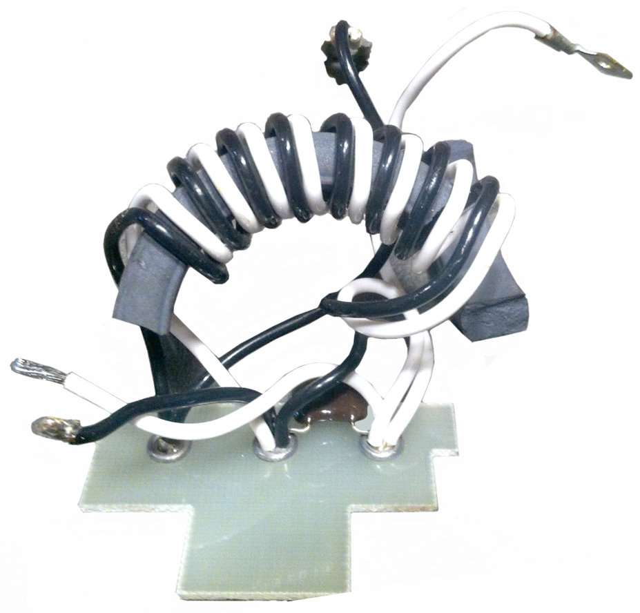
Broken Toriod
Maybe because of a hard mechanical shock or too much RF power the torrid may break.
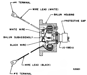
Fig 1
White to RF Type-Nf center
Black to RF Type-Nf ground
Cap: CM05ED-240J03 (Mica 24pF 500V 5%)
Toroid is ID 1.375 (1 3/8), OD 1.875 (1 7/8) and H .375 (3/8)
Fig 2
Fig 3
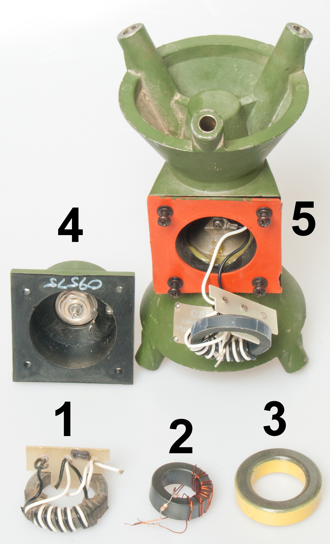
Fig 5
Fig 5 Items:
1. Good replacement assembly
2. FT140-43 from Kits and Parts
3. Unknown toroid.
4. Coax feed
5. Feed cone with broken toroid.
Fig 6 There is only one way to install the connector
cap because the bolt pattern is not symmetrical.
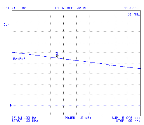
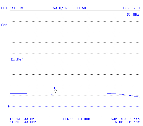
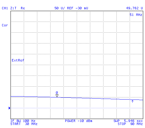
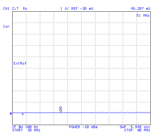
Measured Impedance of transformers with cap.
1. Good replacement assembly
tested with existing 24 pf cap
2. FT140-43 from Kits and Parts
tested with 25 pf cap
3. Unknown toroid.
5. Feed cone with broken toroid.
Conversion: Z:Transform
Network: R
After
CAL
Response
Short
Done
Note: The above data is based on small signal measurements. When power is applied (say 25 Watts) then the core needs to keep working. This is very different from small signal measurements. That's to say the above measurements apply to receiving signals, but may or may not apply transmitting.
One way to check how well a coil works is to make two of them and connect back to back. Then drive a 50 Ohm load and see how hot they get and what the VSWR looks like.
2.1 Before You go into the Field
Your hands can get quite cold, so it's best to have every thing prepared before you start to set up the antenna.
Be sure that the guy ropes do not have a bunch of extra knots from the last installation (there is no need for extra knots).2.2 In the Field
There are 4 guy ropes arranged at 90 degree intervals on a 25 foot radius (50 Foot diameter) circle. Two of these are in line with the hinge that is used to tilt the mast up and down and the other two are at right angles. This allows the guys at the sides to keep the mast lined up as it is raised or lowered.There are blue (water on the ground) and red (hot sun) color coding on a number of the parts. The blue parts are installed closest to the ground and the red parts are at the top. It is possible to use only the blue parts for a shorter mast, and that's what I am now working on doing. Easier to put up and down for testing some ideas.
Before doing anything with the feedcone, I titled up the mast by it's self and got the lengths of the 4 guy ropes correct. This is very easy to do without the weight of the feedcone and elements.
A chair comes in very handy to hold up the mast while the feedcone is fitted. I installed the insulating section on the feedcone and the top three elements. then after the feedcone was attached to the mast I installed the lower three elements.
There is a special mast section with a notch in one and and a red band painted on the other. This section is used to connect to the Blue (big) lower sections and reduce the size for the Red upper sections. It must be used in all installations, because a smaller diameter (Red) section must be there for the insulating section that holds the Feedcone.
Rather than use the Strain Relief PF-211/G, I used tie wraps to secure the coax to the mast. This works much better and faster. You can see the tie wrap tails in the photo above.
See Drive Testing for more information.
If you want to connect to coax cables toghther for a longer run you will need a type-N male to male barrell NSN 5935-01-035-5650.
3.1 Frequency Coverage
The 3.5:1 VSWR specified bandwidth is 30 to 88 MHz.
Testing using the Agilent 4395A Spectrum Analyzer shows it is better than the Radio Shack 20-176 over the 88 to 108 FM radio band.
Note when evaluating a receiving antenna the spectrum plot is more important than the VSWR plot. Even better is the signal quality vs. frequency plot you get from the chirp receiver, but that only covers the HF band.
Radio Shack 20-176 Scanner Ant Spectrum Display of FM Broadcast Band
This is a way to compare the OE-254 or Radio Shack antennas to see how well they work on the FM broadcast band.
The Radio shack is working in it's frequency range, but the OE-254 is working above it's range. The OE-254 performs much worse that the Radio Shack in the FM band. That indicates that the balun in the OE-254 is probably optimized for 30 to 90 MHz.
OE-254 Antenna FM broadcast band Spectrum Plot
The OE-254 works fairly well as an FM antenna.
OE-254 Smith Chart 30 to 108 MHz
30 - 108 MHz, marker 0 @ 30, Mkr 1 @ 88, Main Marker at 51 (Z=63 -16j)
In this case the OE-254 has a reasonable VSWR in the Fm broadcast band (88 to 108 MHz), but it does a poor job in that band receiving signals.
See the PS magazine articles below.For some parts contact Steve Haney of Haney Electronic Company.
| Description |
|
|
|
|
|
|
| Antenna OE-254/GRC |
|
|
|
|
| Description |
|
|
|
|
|
|
| Extension, Insulating |
|
|
|
|
|
|
| Feedcone Assembly AS-3166/GRC |
|
|
|
|
|
|
| Mast Section AB-24/GR |
|
|
|
|
|
|
| Mast Section MS-116A |
|
|
|
|
|
|
| Mast Section MS-117A |
|
|
|
|
|
|
| Antenna Tip Assembly |
|
|
|
|
|
|
| Mast AS-1244/GRC or Mast AB-1244B/GRC |
80058 |
|
|
|||
| Bag, Transit - Packing & Setup Instructions |
|
|
|
|
|
|
| Deleted |
|
|
|
|||
| Connector, Adapter TRU-2064 |
|
|
|
|
||
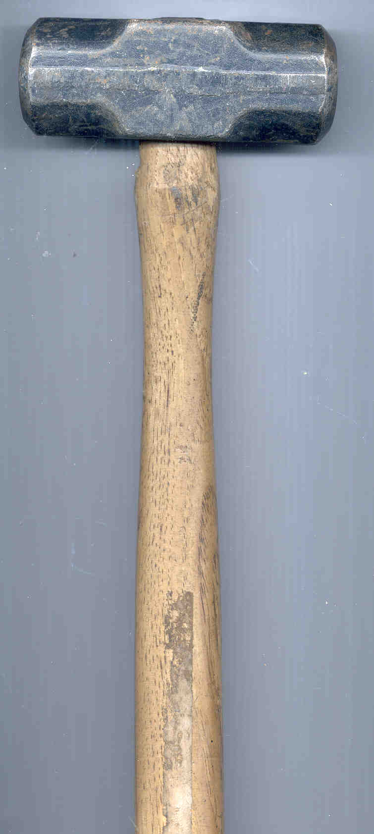
| Hammer Hand, 2-1/2? lb. Type X, Class 1 |
|
|
|
|
|
|
| Running Spares |
C7 |
9 - 12 , 14 |
||||
| Technical Manual: TM 31-5985-357-13 |
|
|
|
|
| Description |
|
|
|
|
|
|
| Adapter Assembly, Lower |
|
|
|
|
|
|
| Adapter Assembly, Upper |
|
|
|
|
|
|
| 80 Ft. Cable Assembly, Radio Frequency CG-1889C/U |
|
|
|
|
|
|
| Clamp, Electrical Conductor, Strain Relief PF-211/G |
|
|
|
|
|
|
| Guy Assembly |
|
|
|
|
|
|
| Guy Assembly |
|
|
|
|
|
|
| Guy Plate |
|
|
|
|
|
|
| Guy Plate |
|
|
|
|
|
|
| Mast and Base Assembly |
|
|
|
|
|
|
| Mast Section Assembly, Lower |
|
|
|
|
|
|
| Mast Section Assembly, Upper |
|
|
|
|
|
|
| Base Plate |
|
|
|
|
|
|
| Stake, Base Plate |
|
|
|
|
|
|
| Stake Assembly, Guy |
|
|
|
|
|
|
| Description |
|
|
|
|
|
|
| Adapter Assembly, Lower Blue |
|
|
|
|
|
|
| Adapter Assembly, Upper Red |
|
|
|
|
|
|
| 80 Ft. Cable Assembly, Radio Frequency CG-1889C/U |
|
|
|
|
|
|
| Clamp, Electrical Conductor, Strain Relief PF-211/G |
|
|
|
|
|
|
| Guy Rope Assembly Blue |
|
|
|
|
|
|
| Guy Rope Assembly Red |
|
|
|
|
|
|
| Guy Plate Blue 1 11/16" I.D. |
|
|
|
|
|
|
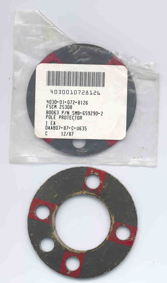
| Guy Plate Red
1
1/2" I.D. Pole Protector Red |
4030-01-072-8126 |
|
|
2S308 |
|
|
| Mast and Base Assembly |
|
|
|
|
|
|
| Mast Section Assembly, Lower 2' 7" functional len |
|
|
|
|
|
|
| Mast Section Assembly, Upper 2' 3" functional len |
|
|
|
|
|
|
| Base Plate |
|
|
|
|
|
|
| Stake, Base Plate |
|
|
|
|
|
|
| Stake Assembly, Guy |
|
|
|
|
|
|
TM 11-5985-357-13 (Radio Nerds: pdf, Feb 1991
FM 24-19 - -Section IV. Antenna Group OE-254/GRC -
FM 24-24 - Chapter 4 -
Steve Haney - antennas and other mil radio stuff
NSN List Dec99.pdf - by The Romad Locator -
Fair Radio - AB-1244/GRC Mast Kit - Used on the OE-254, RC-292 and OE-303 AntennasPS magazine
2003PS magazine Issue 604 March 2003 pages 44 & 45 "OE-254 Antenna Advice" is my article on the OE-254 that corrects the error in issue 560.2002
Maintain 'em to Stand Tall 596 42 - 45
2000
Be a Rust Buster 582 (no correction for wire problem above)
Double Staking in Loose Ground 577 51
1999
Subject ______________ Vol pageAntenna support sleeves 560 52 Is It Modified?1998
Feedcone assembly, elements, cables 560 48 -Before you raise'em....you better maintain'em - There is an error on the bottom of pg 49 it says "Try substituting wire for the cord. The locking wire NSN 9505-293-4208, used in your arms room will work.
THIS IS WRONG, USING WIRE WILL SHORT OUT THE ANTENNA AND MAY BURN UP YOUR RADIO!!!!!!
OE-254, RC-292--Safety tips 545 50
1997
Mast section MWO 531 53
Facing the Feedcone Facts 536 36
1996
Twisting the Rust Away - Feedcone cleaning 518 43
The Feedcone That Couldn't Resist 529 45 - essentially a short everywhere because of the balun
Staking Technique 525 48
1995
Anenna Safety - A Tall Order 506 46 - tip caps NSN 5985-00-930-7223 & electrical tape
1994
Antenna PMs a Tall Order 500 46 - 48
Gone With The Wind 494 50-53 m It's OK to use insulating cord to hold the cone toghther.
Get The Point 504 47
1992
Right Lube Means Clear Signal 472 44, 45 Water Displacing Compound
1991
Good PM Thaws Frostiest Antennas 468 40, 41
Cable Adapter NSN 465 61
1990
Antenna Peak Points 455 42, 43
RF Currents on the Outside of the Coax
The existing design uses a 30" insulating mast section just below the feedcone, but still has the coax going down the mast. The effect of the coax is to short out the vertical component of the lower antenna elements and that's the key radiating polarization. It may be a good idea to place ferrites (RS 273-104 7/16"x7/8" or 273-105?) at the base of the feedcone and at the joint between the metal mast and insulating mast section to block any RF currents running on the outside of the coax. The effect may show up in the impedance looking into the end of the coax or in signal strength.New Feedcone Design
An improvement might be to design the center insulator to both be much stronger and also to have the option of mounting the biconical elements in a horizontal configuration. This would change the polarization from vertical to horizontal and double the broadside gain and add two nulls off the sides. It would be interesting to see the effect on range with the other radio running vertical and horizontal polarization. By turning the feedcone 90 degrees to the horizontal position the uppermost mast section can now be metal because it would be orthogonal to the active antenna polarization.
Agilent E4404B ESA-E 9kHz - 6.7 GHz Spectrum Analyzer - Accessories (including many antennas)
AS-2360 HF Loop Antenna Parts List
Antennas
Antenna Adapters for sale made by N6GCE
AS-1405/PRC-41 UHF Antenna
AS-1729/VRC VHF Vehicle Antenna that uses the MX-6707 Base , AS-1720/VRC & AT-1095/VRC Antenna elements
AS-2109 VHF low band VHF Antenna (simulates either the AT-271 or AT-892 on the PRC-77
AS-2259/GR HF NVIS Antenna and NVIS in General
AS-3588/GRC-206 VHF-AM & UHF-AM Antenna
AT-1011/U aka Shakespeare 120 HF Antenna - 16' or 32' whip
AT-271/PRC 10' Fishing Pole Antenna used on many radios both HF and VHF
AT-984/G Fishing Reel Antenna used for both HF and VHF
Eyring Low Profile HF Antenna 301A (ELPA 301A)
GRA-50 Antenna, HF NVIS Dipole w/reels at the ends
30 to 88 MHz VHF Low Band Antennas
AMRAD LF Active Whip Antenna
LST-5B UHF radio w/ D&M C152-1-1 SATCOM Antenna
WWVB (6o kHz) Loopstick Antenna & C-Max Receiver
OE-254/GRC Antenna Group - this page
OE-303 1/2 Rhombic VHF Antenna
PRC-68 Family Antenna Adapter 68AA with DC return
RC-292 Antenna, VHF low band mast mounted & MS & AB mast elements & Batt Adapter for PRC-8, PRC-9 & PRC-10
SATCOM Antenna UHF - Dorne & Margolin C152-1-1
Shortened Antennas for Portables by Dennis Starks
SORAK Special Operations Radio Antenna Kit OE-452/PRC Five Configurations HF through VHF coverage
Trivec-Avant AV 2095 UHF Satcom Antenna System - Gyroscope keeps vehicle mounted antenna pointed as satellite.
TRQ23 Radio Receiving Set AN/TRQ-23 Antenna Group OE-4/GR AS-2360 Series Loop Antennas
URM-182A/TS-3754 VHF Low Band Power Meter - 10 and 100 Watt Full Scale, both forward and reverse - improved version of the TS-2609
Wire Antennas - TCI651 HF Ant, mainly about Camouflage Netting Mast Kits, including antenna line launchers CSV17 Tennis ball and EZ-Hang Slingshot
Return to Brooke's PRC68, Alphanumeric web page index, Contact, Products for Sale, Squad Radio, Battery, PRC-68B, PRC-126, Electronics or Home page
page created 28 Dec. 2000.


