Radar, Sonar & Optical Pulse
These are "time of flight" systems
where the round trip propagation time is measured and divided by
twice the propagation velocity. Time of flight is used in
modern digital optical range finders like the
Bushnell
golf binoculars and the
Laser Technology
Criterion units. These typically have one lens for
the outgoing pulse of IR light and a separate lens to focus the
light on a fast photo sensor.
Optical
Coincidence rangefinder (Wiki)
A single point on the target is brought into alignment to get
the range, so the point of the triangle is at the
target. This has the advantage that you do not need to
know
any dimensions of the target, but the disadvantage that the
instrument gets very large if you need to range up to1,000
yards or longer.
The range finder works by having a known separation of the
two sight lines in the instrument. So, the separation
between the sight line needs to increase as the range
increases.
For example a camera focusing rangefinder may have an inch or
so separation to range to maybe 30 feet, but to range to 100
yards (300 feet) requires about 6 feet separation.
The Edscorp Field Range Finder
has a separation of a couple of inches and can range to about
100 feet.
|
921137
Range-finder, Albert
A Michelson, (Speed of Light)
1909-05-11, - |
|
1030846
Range-finder, Albert
A Michelson,1912-06-25, -
|

|
1168650
Binocular telescope, Frederick
L G Kollmorgen, Keuffel
and Esser Co, 1916-01-18, 359/417; 359/726 -
Also see these related web pages:
Submarine Periscopes
Panoramic
Telescope M12 patents
|
Image fuzziness
Image property range finders are used in modern digital
cameras. One way these work is to look at the image
contrast as the lens is set a various focal lengths. The
highest contrast image is deemed to be the best focused.
The position of the lens is calibrated in distance to the
subject. There are a number of other methods employed in
digital cameras that analyze the pixels and the focus motor
changes the lens focus. When they are done the best
focus has (most of the time) been achieved and the camera and
the EXIF data (Wiki)
in the photograph data file reports the distance.
Stadimeter (Wiki)
A single point in the instrument forms a triangle where the
other two points are at the target. The disadvantage is
that you need to know some dimension of the target, such as
the height of the top of a ships. main mast above the water
line, the height of a man's head, the height or length of a
vehicle, etc. The advantage is that the instrument can
be small like a rifle telescopic sight (Wiki: angular mil,
Mil
Dot sight), surveyor's telescope or the ship's
Stadimeter.
The surveyor's method of stadia
depends to tick marks on the telescope reticule that include
an angle of 10 milli radians (Wiki)
so that if there's a separation on the rod of 1 foot (between
the top and bottom stadia marks) then the rod is 100 feet
away.
One of the oldest optical ranging systems is based on the
concept of
stadia. The idea is
that you can determine distance by measuring the included angle
of an object of known height.
Examples:
K&E 76 0000 Alidade,
Leitz 115A transit,
Stadimeter (
Wiki)
This method is also known as
Tacheometry
(
Wiki).
The early surveying telescopes that implemented the method of
stadia had a problem in their optical system that made the
formula for the distance from the center of the instrument equal
to 100 times the rod intercept PLUS a correction term (maybe 1
foot). All the newer instruments have a correction term of
zero.
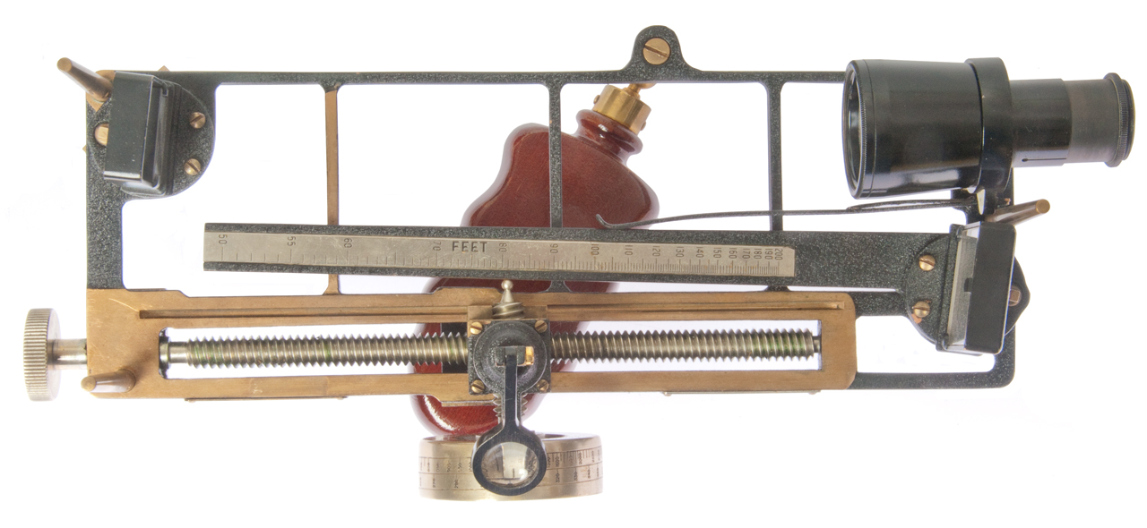
1942 Stadimeter (bar type) (Mk 1?)
Fig 1

|
|
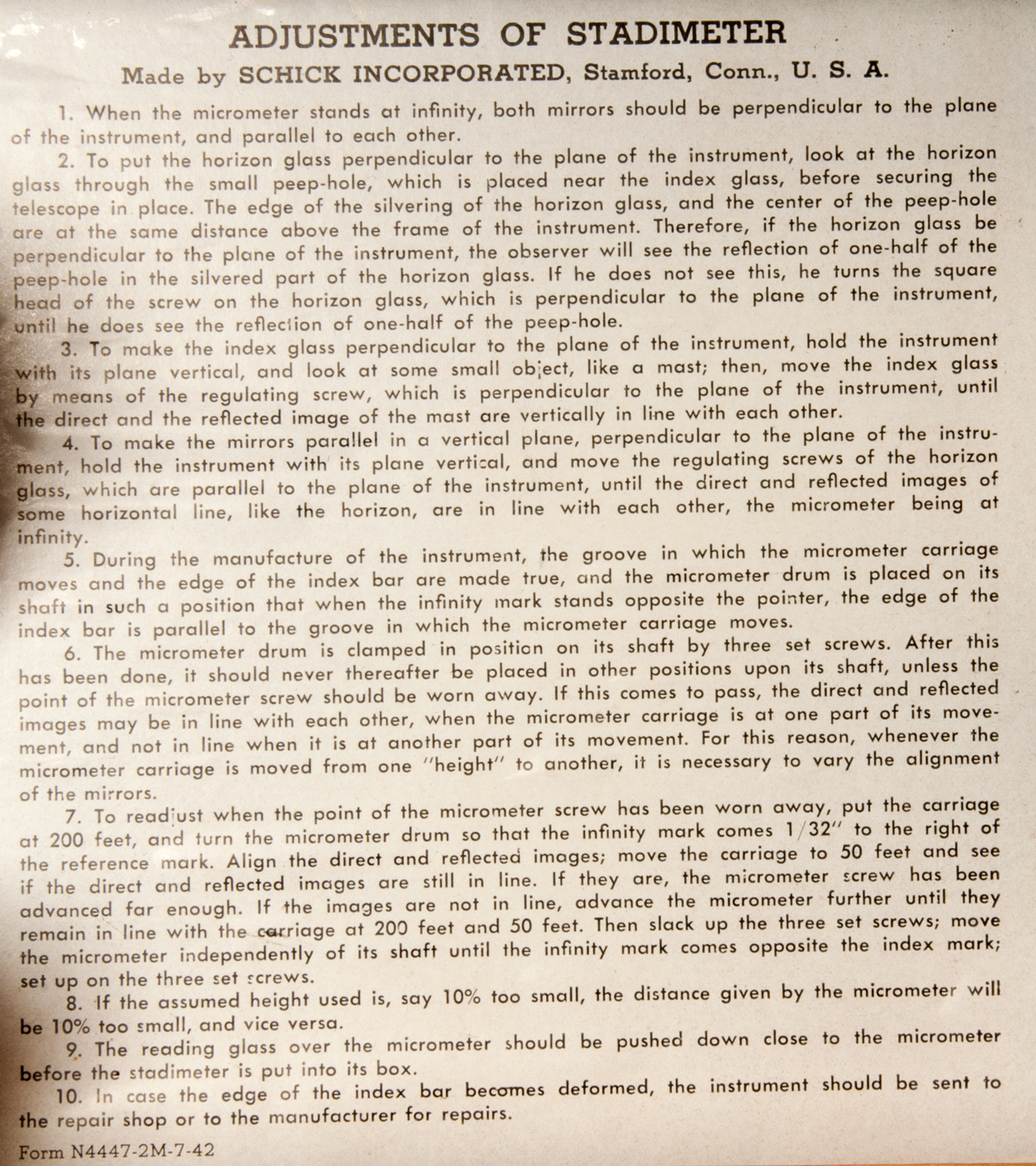
Fig 2 Adjustment Instructions

|
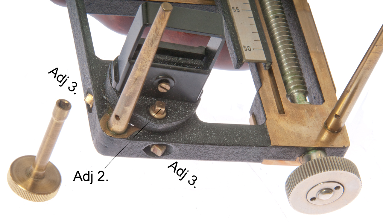
Fig 3 Adjustment Step 2 Peep hole and
Index Glass (3)
(telescope has been removed)
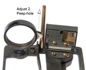
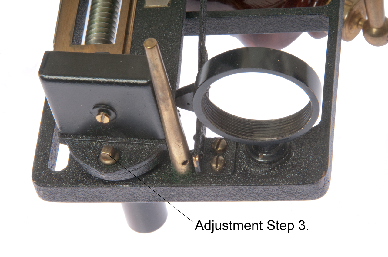
Fig 4 Horizon Glass (4) adjustments step 2 and step 3
& step 4.

Fig 5 Index Glass Adjustment step 3.

|
Stadimeter Mk III

|
Stadimeter Mk V (photo from Wiki)
Sextant type (see patents below)
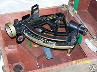
|
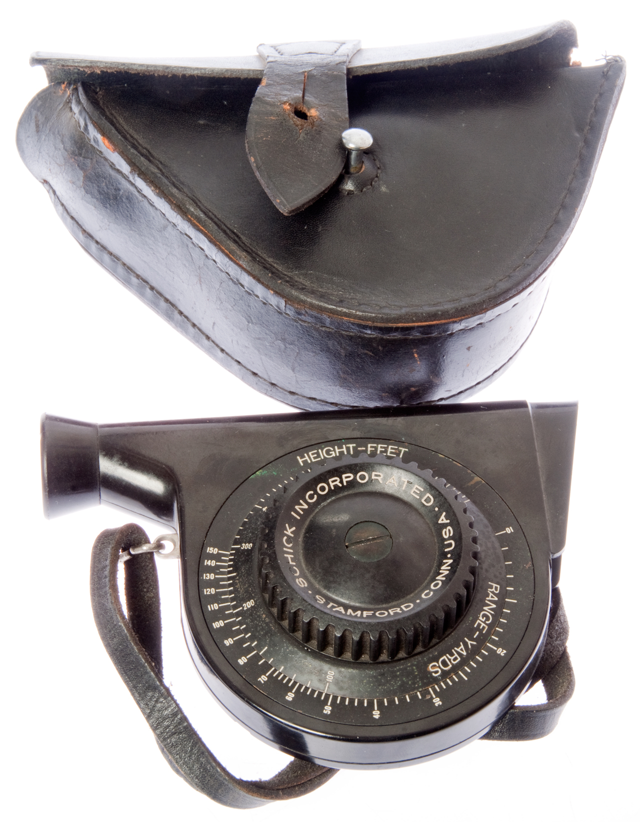
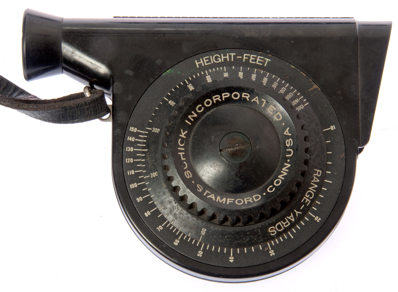
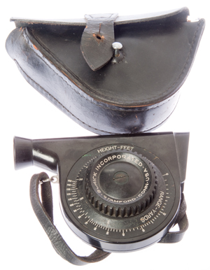
Stadimeter Mk III
(Circular type)
|
|
Fig III-1
|
Fig III-2

|
Fig III-3
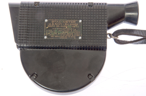
Stadimeter
U.S. Navy-Bu. Ships
Mark III-Mod.[ ]-1942
-Instructions-
Rotate knob until object is spanned
between line on glass and movable sight.
Read Range opposite known height.
(If length instead of height is known,
use instrument on its side).
Patented
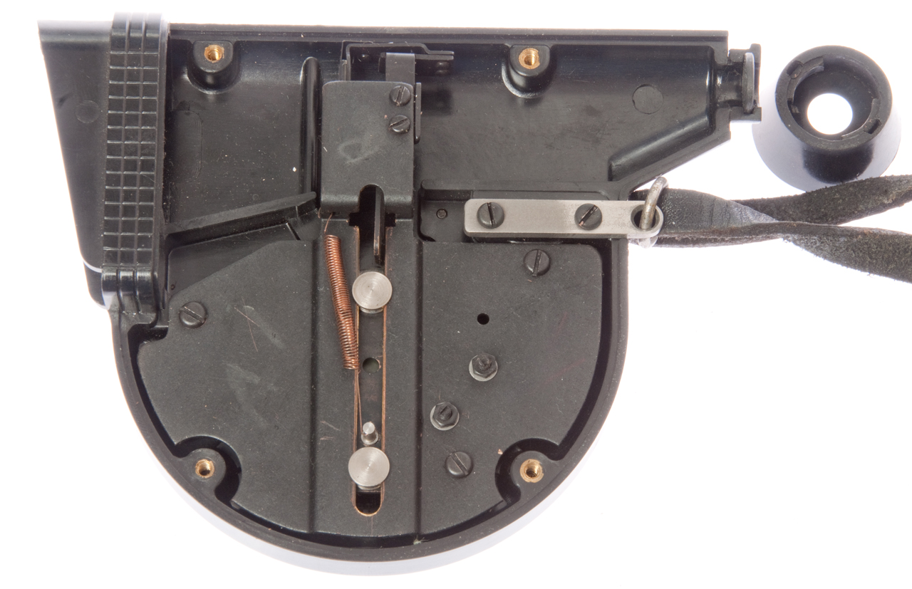
Fig III-5

Rotating knob rotates cam that raises post sight.
Glass with line is fixed. At top there's an
adjustment screw to set zero.
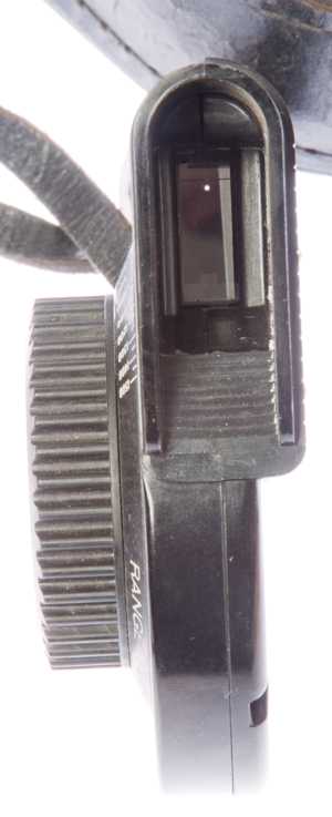
|
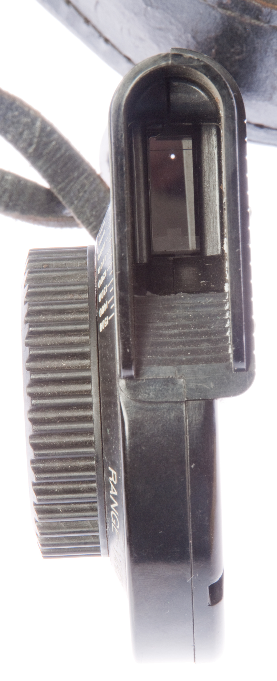
Fig III-4
Near top you can see line on glass just above dot of
light from
pinhole. Near bottom you can see post sight.
|
213018 Surveying
Instrument,
Henry
S. S. Watkin, Mar 4, 1879,
356/20 -
complex
406829 Range Finder,
Bradley
A. Fiske (Wiki),
Jul 9, 1889,
33/280 - electrical bridge
523721
Method and apparatus for Range Finding,
Bradley
A. Fiske, Jul 31, 1894,
356/22
- bar type
801578 Range Finder,
Bradley
A. Fiske (Western
Electric Co.), Oct 10, 1905,
356/22
- two horizontal angle measurements for nautical use
1208120
Instrument for Measuring Distances Optically, B
radley
A. Fiske, Dec 12, 1916,
356/22 -
ship for use with gun
D132595
Stadimeter c
hassis, Douglas
F. Linsley (Schick
Inc.), Jun 2, 1942,
D10/70 - bar
type
2295877
Stadimeter Gearing,
William
A. Thomas (
Schick
Inc.), Sep 15, 1942,
74/422 ; 356/22; 74/405;
74/406 - bar type
2315343
Backlash take-up,
Linsley
Douglas F (Schick
Inc.), Mar 30, 1943,
74/441
2403965
Stadimeter,
Brandon
Thomas O, Jul 16, 1946,
356/22 - sextant type - lower cost
to manufacture since it uses common sextant design
3459478 Stadiametric rangefinder
including a transversely movable lens, Walter
W Hollis, Paul
M Marasco (U.S.
Army), Aug 5, 1969,
356/22 -
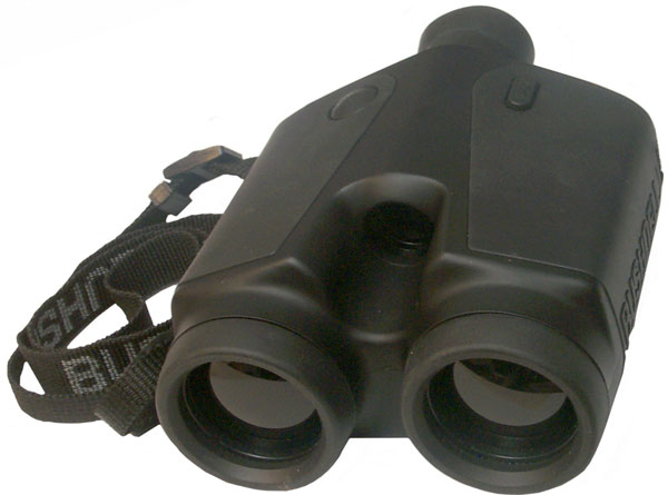
Bushnell Golf Yardage Pro 400 Binoculars
One objective lens is for the IR
transmitter and the other is for the IR receiver. There is
a small visual telescope in the center that's for the operator
to observe where the spot is pointing. The two large lens
are black in color, not clear like optical
binoculars.
The range is displayed in units of either meters or yards, a
little to coarse for
surveying.
Laser Technology Criterion
This is the model 400 that includes tree measuring
functions. The range is displayed in 1/100 of a meter, i.e.
a cm which is less than 1/2" so are excellent for surveying.
In fact part of the set is a fork mount that fits a standard
surveying tripod.
Operation
After power on you will see one of the top menus. Use the up
or down arrows to scroll to the desired menu. In my case
they are:
TREE
CONDUCTOR CLEARANCE
SURVEY
SYSTEM
TREE
Once you have selected the appropriate top menu press the ENTER
button. For Example:
POWER (on)
<down>
<down> i.e. SURVEY
ENTER i.e. BASIC MEASUREMENTS
ENTER display is:
HD:-------.-- M
AZ:------.- DEG
<press trigger>
display blanks change into data and pressing up or down scroll
arrow shows more data like inclination, slope distance, etc.
When in Survey measurement mode and the trigger is pressed you
hear a buzzing sound as the laser range finder and other sensors
are working. When aimed at a wall about 4 feet away the spot
size as viewed using the
PAS-6 IR scope
is about an inch high and half an inch wide.
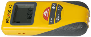
eBay search term: "Prexiso X2". Price range: $100
Range: up to 98 feet with 1/16" resolution (or) 30m with 1mm
resolution.
Pressing + or - between distance measurements allows adding or
subtracting them.
To measure [Area - Volume - Triangle] press the key [once,
twice or three] times prior to making a measurement.
The upper left of the LCD shows the reference plane: either
the front or back (shown in photo). Pressing the units
key toggles between front and back.
Pressing and holding the units key gets you into the units
mode.
Outside in the daytime it's difficult to locate the red laser
pointer spot on natural vegetation. Getting the spot
onto a 5 gallon white plastic paint bucket at 30 feet is
difficult. But when you press and hold the "Laser On"
button for a few seconds to turn on continuous measure mode
it's easy to start close to the bucket and back away while
maintaining the spot. It might be easier to use outside
at dawn or dusk. Need white or reflective targets, not
trees or bushes.
Lasertech TruPulse
The TruPulse units are much smaller and more capable than the
Criterion (
above).
There are a couple of models (200 and 360) as well as some
options.
The 200 does not have azimuth (compass), but the 360 does have a
compass.
A "B" suffix means Bluetooth output instead of wired RS-232
output.
The "R" suffix means Rugged & better water proofing (also have
horizontal format and black color - looks more military) heavier
and uses only CR123 batteries, no AA like the other models.
Rough pricing (2014) 200: $600, 360: $1000, 360R: $ 1800
Northrup Grumman Mk VII Laser Target
Locator
I do not have this, but there are patents shown on the label:
6204961 Day and night sighting system, Litton
Systems, Inc., Mar 20, 2001, - about
combining day and night time optics for a rifle sight
5608744 Compact laser apparatus and method, Litton
Systems, Inc., Mar 4, 1997, - efficiently
produces an eye safe 5-10 mJ at about 1.58 μm in a small package
5675594 Compact laser apparatus, Litton
Systems, Inc., Oct 7, 1997, - very
similar to 5608744
4746201 Polarizing apparatus employing an optical
element inclined at brewster's angle, Gordon
Gould (Patlex Corp), Filed: Jan 16, 1978,
Pub: May 24, 1988, - Gordon holds
4053845
Optically pumped laser
amplifiers which was Filed: Aug 16, 1974 and is one of
the fundamental patents on LASER technology.
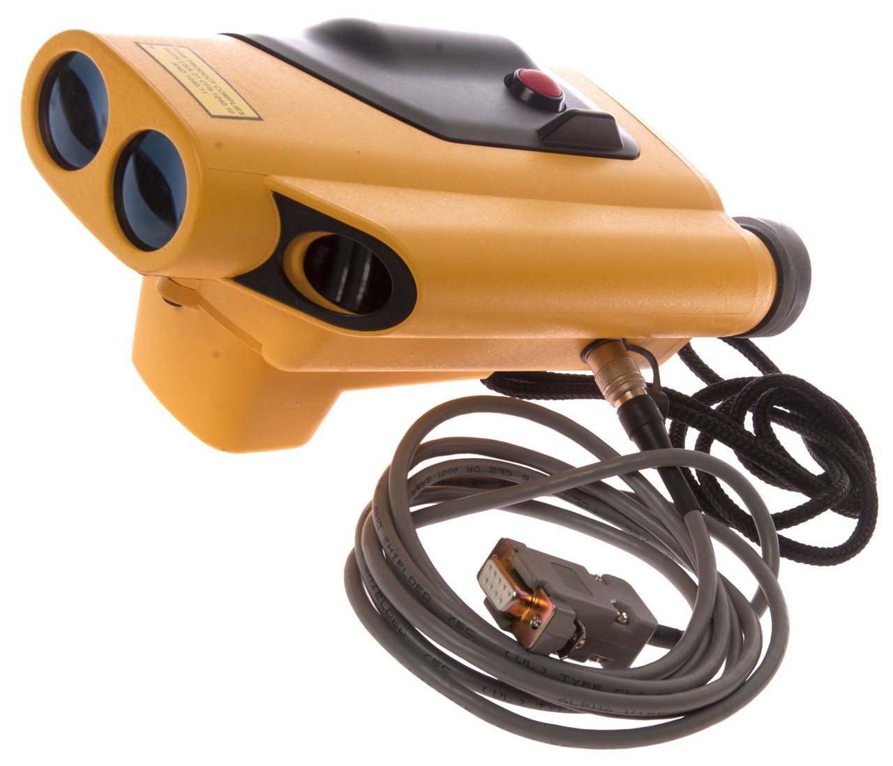
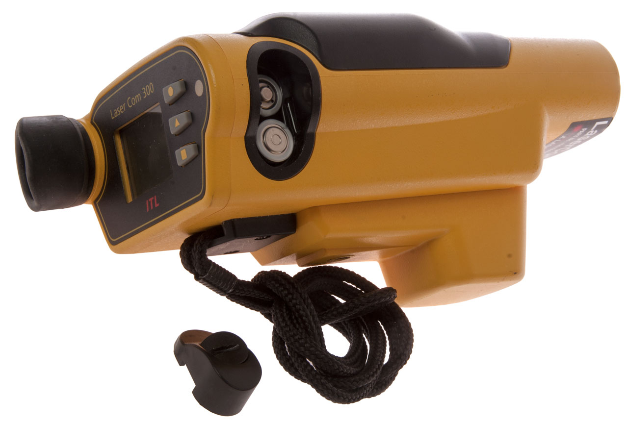
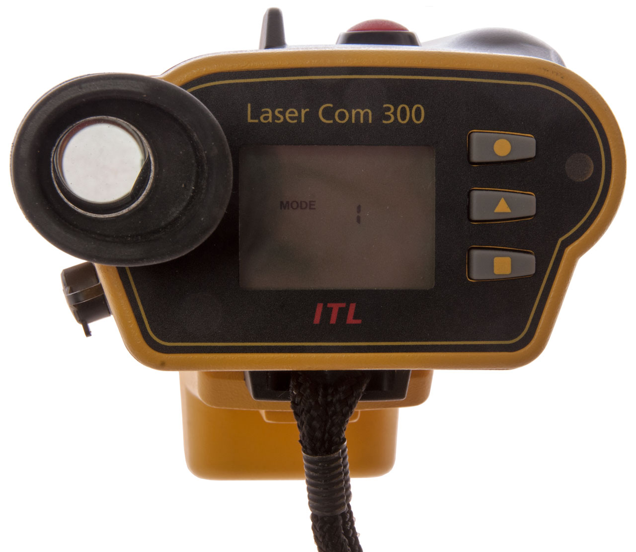
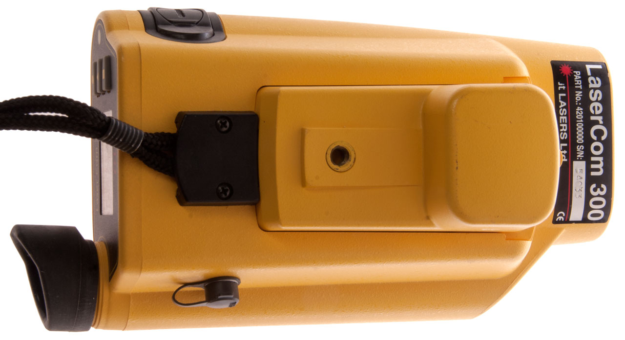
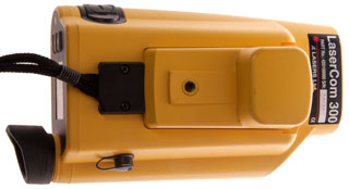
ITL
LaserAce 300
Measurement Devices Ltd may have been purchased by Renishaw,
including their Boretrak
system. The handheld laser rangefinder was part of
the Boretrak system.
Fig 1 Has optional Magnetic compass and
RS-232 cable.

|
Fig 2 uses 2 each AA batteries
 |
Fig 3 Photo did not pick up red dot seen in
sight.
 |
Fig 4
 |
|
|
|
|
|
Has compass and elevation sensors and serial data output.
But don't know if it will directly interface with
DAGR.
WO1990012330A3
Hand-held laser rangefinder,
Steven Ball,
Measurement Devices Ltd,
1990-12-13 - probably this device, but no figures on Google
6141091
Surveying apparatus,
Stephen Ball,
Measurement Devices Ltd ,
2000-10-31
IEEE Spectrum, Vol. 18, No. 11, November 1981, IEEE, (New York,
US), A.V. JELALIAN: "Laser Radar Improvements", pages 46-51 see
page 47 *
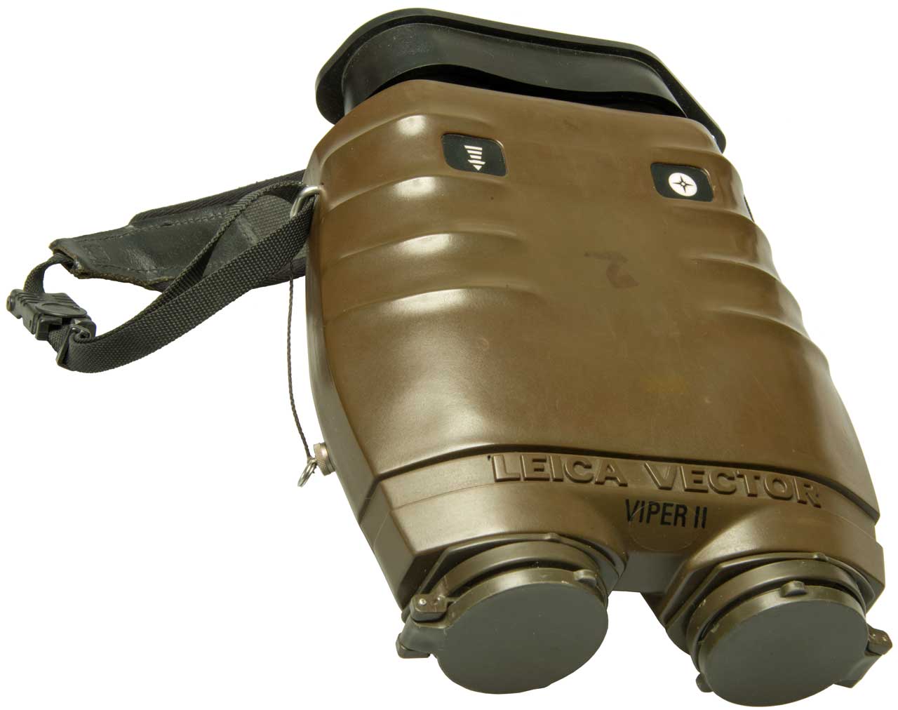
Vertronix Victor 21
The following description from US patent 8471906
Miniature celestial direction detection system (See Stellar
Time\Daytime_Stellar_Imager).
"The
Victor
21 binoculars, available off-the-shelf from Vertronix with
offices in Heersbrugg, Switzerland are stabilized by a precision
miniature gyroscope mounted on a gimbaled platform in the middle
of the optical pathway. A gyro stabilized binocular rejects almost
all image motion caused by hand tremor and platform vibration. It
has a 7× magnification and stabilization freedom of ±8 degree. A
laser range finder uses a miniature eye safe laser, which is
capable of sending a beam out to several kilometers and it
provides good signal-to-noise ratio without placing a high burden
on the power supply. The laser rangefinder has an accuracy of ±2 m
at 5 km range. For target identification and location the Victor
21 binoculars can are equipped with a digital magnetic compass and
co-located with a GPS unit. The digital magnetic compass mounted
on the binoculars provides an azimuth and elevation angle (in
digital format) of the binocular pointing direction and the laser
range finder provides the range to the target, all relative to the
location of the binoculars and the GPS unit provides the location
of the binoculars in latitude and longitude. Existing computer
software is available for quickly determining the latitude,
longitude and elevation (above sea level) of the target from a
combination of the information provided by the digital magnetic
compass, the range finder and the GPS unit."
The output from these is directly compatible with the
PLGR and
DAGR
GPS receivers. Most of this web page has been looking for
units with similar functionality, but much much lower in cost.
[an error occurred while processing this directive] page created 8 Oct
2009.